EP2034474A1 - Actionneur de bras de suspension pour un dispositif de balayage - Google Patents
Actionneur de bras de suspension pour un dispositif de balayage Download PDFInfo
- Publication number
- EP2034474A1 EP2034474A1 EP08305496A EP08305496A EP2034474A1 EP 2034474 A1 EP2034474 A1 EP 2034474A1 EP 08305496 A EP08305496 A EP 08305496A EP 08305496 A EP08305496 A EP 08305496A EP 2034474 A1 EP2034474 A1 EP 2034474A1
- Authority
- EP
- European Patent Office
- Prior art keywords
- suspension arm
- magnet
- recess
- actuator according
- lever
- Prior art date
- Legal status (The legal status is an assumption and is not a legal conclusion. Google has not performed a legal analysis and makes no representation as to the accuracy of the status listed.)
- Granted
Links
- 239000000725 suspension Substances 0.000 title claims abstract description 74
- 230000000977 initiatory effect Effects 0.000 claims abstract description 11
- 238000005457 optimization Methods 0.000 claims abstract description 8
- 230000003287 optical effect Effects 0.000 claims description 21
- 230000005484 gravity Effects 0.000 claims description 4
- 239000000969 carrier Substances 0.000 claims 1
- 230000035945 sensitivity Effects 0.000 abstract description 5
- 230000015572 biosynthetic process Effects 0.000 description 3
- XEEYBQQBJWHFJM-UHFFFAOYSA-N Iron Chemical compound [Fe] XEEYBQQBJWHFJM-UHFFFAOYSA-N 0.000 description 2
- 239000004743 Polypropylene Substances 0.000 description 1
- 229910052742 iron Inorganic materials 0.000 description 1
- 229910001172 neodymium magnet Inorganic materials 0.000 description 1
- -1 polypropylene Polymers 0.000 description 1
- 229920001155 polypropylene Polymers 0.000 description 1
- 229910052761 rare earth metal Inorganic materials 0.000 description 1
- 150000002910 rare earth metals Chemical class 0.000 description 1
Images
Classifications
-
- G—PHYSICS
- G11—INFORMATION STORAGE
- G11B—INFORMATION STORAGE BASED ON RELATIVE MOVEMENT BETWEEN RECORD CARRIER AND TRANSDUCER
- G11B7/00—Recording or reproducing by optical means, e.g. recording using a thermal beam of optical radiation by modifying optical properties or the physical structure, reproducing using an optical beam at lower power by sensing optical properties; Record carriers therefor
- G11B7/08—Disposition or mounting of heads or light sources relatively to record carriers
- G11B7/09—Disposition or mounting of heads or light sources relatively to record carriers with provision for moving the light beam or focus plane for the purpose of maintaining alignment of the light beam relative to the record carrier during transducing operation, e.g. to compensate for surface irregularities of the latter or for track following
-
- G—PHYSICS
- G11—INFORMATION STORAGE
- G11B—INFORMATION STORAGE BASED ON RELATIVE MOVEMENT BETWEEN RECORD CARRIER AND TRANSDUCER
- G11B7/00—Recording or reproducing by optical means, e.g. recording using a thermal beam of optical radiation by modifying optical properties or the physical structure, reproducing using an optical beam at lower power by sensing optical properties; Record carriers therefor
- G11B7/08—Disposition or mounting of heads or light sources relatively to record carriers
- G11B7/085—Disposition or mounting of heads or light sources relatively to record carriers with provision for moving the light beam into, or out of, its operative position or across tracks, otherwise than during the transducing operation, e.g. for adjustment or preliminary positioning or track change or selection
- G11B7/0857—Arrangements for mechanically moving the whole head
- G11B7/08576—Swinging-arm positioners
-
- G—PHYSICS
- G11—INFORMATION STORAGE
- G11B—INFORMATION STORAGE BASED ON RELATIVE MOVEMENT BETWEEN RECORD CARRIER AND TRANSDUCER
- G11B21/00—Head arrangements not specific to the method of recording or reproducing
- G11B21/16—Supporting the heads; Supporting the sockets for plug-in heads
- G11B21/20—Supporting the heads; Supporting the sockets for plug-in heads while the head is in operative position but stationary or permitting minor movements to follow irregularities in surface of record carrier
- G11B21/21—Supporting the heads; Supporting the sockets for plug-in heads while the head is in operative position but stationary or permitting minor movements to follow irregularities in surface of record carrier with provision for maintaining desired spacing of head from record carrier, e.g. fluid-dynamic spacing, slider
-
- G—PHYSICS
- G11—INFORMATION STORAGE
- G11B—INFORMATION STORAGE BASED ON RELATIVE MOVEMENT BETWEEN RECORD CARRIER AND TRANSDUCER
- G11B7/00—Recording or reproducing by optical means, e.g. recording using a thermal beam of optical radiation by modifying optical properties or the physical structure, reproducing using an optical beam at lower power by sensing optical properties; Record carriers therefor
- G11B7/08—Disposition or mounting of heads or light sources relatively to record carriers
- G11B7/085—Disposition or mounting of heads or light sources relatively to record carriers with provision for moving the light beam into, or out of, its operative position or across tracks, otherwise than during the transducing operation, e.g. for adjustment or preliminary positioning or track change or selection
-
- G—PHYSICS
- G11—INFORMATION STORAGE
- G11B—INFORMATION STORAGE BASED ON RELATIVE MOVEMENT BETWEEN RECORD CARRIER AND TRANSDUCER
- G11B7/00—Recording or reproducing by optical means, e.g. recording using a thermal beam of optical radiation by modifying optical properties or the physical structure, reproducing using an optical beam at lower power by sensing optical properties; Record carriers therefor
- G11B7/08—Disposition or mounting of heads or light sources relatively to record carriers
- G11B7/09—Disposition or mounting of heads or light sources relatively to record carriers with provision for moving the light beam or focus plane for the purpose of maintaining alignment of the light beam relative to the record carrier during transducing operation, e.g. to compensate for surface irregularities of the latter or for track following
- G11B7/0925—Electromechanical actuators for lens positioning
- G11B7/093—Electromechanical actuators for lens positioning for focusing and tracking
Definitions
- the invention relates to a suspension arm actuator for a scanning device with a pickup, in particular with an optical head having a focal lens, to be arranged in a device for recording and/or reproducing information.
- a suspension arm arranged in such a scanning device is usually designed in the form of a two-arm lever and is, in its center of gravity between the two lever arms, provided with a bearing that is arranged on a support in order to allow the suspension arm to make a movement about at least one axis.
- a pickup for example an optical head having a focal lens and intended for emission of a light beam, in particular a laser beam, onto an optical disk (disk-shaped data carrier) designed as an information carrier and for reception of the beam reflected by said optical disk is arranged at one end of said suspension arm. Therein, the disk is supported by a supporting device and is caused to make a rotational motion.
- the end of the suspension arm which is provided with the optical head, is movable in the form of an arc in a plane extending in parallel to the recording surface of the optical disk for tracking and perpendicularly to this plane for focusing.
- the suspension arm is provided with magnetic drives, wherein at least that one of said magnetic drives that is intended for the tracking motion is allocated to the other end of the suspension arm.
- suspension arm actuators are, for example, described in EP-A-0 400 570 , in JP-A-5128580 , in JP-A-2004227760 , in US 2004/0148619 A1 , and in KR 1020040108029 A .
- the suspension arm actuator described in US 2004/0148619 is arranged on a support such that it can be pivoted about an axis and, to achieve said pivoting, comprises a magnetic drive at that end region that is arranged opposite to the optical head having a focal lens, said magnetic drive being formed of a magnetic arrangement permanently arranged on the support and of a coil arranged on the suspension arm, with control of the operating current of said coil.
- the suspension arm On the pivot axis side facing away from the magnetic drive, that is on the side of the focal lens, the suspension arm comprises an elastic region, which supports the optical head at its free end.
- a second magnetic drive formed with the suspension arm is allocated to said elastic region on the head side thereof, said elastic region being partially enclosed by the remaining suspension arm and said second magnetic drive being able to move said free end and, thus, the head in focusing direction.
- the invention aims at designing a suspension arm actuator for a scanning device such that the suspension arm actuator comprises an increased sensitivity.
- a suspension arm actuator for a scanning device comprising a suspension arm designed as a two-arm lever and mounted to a support between the lever arms such that it can be pivoted about a pivot axis extending perpendicularly in relation to the suspension arm, wherein one lever arm is provided with a recess to allow a swivel motion of the suspension arm.
- the inner leg of a yoke having a U-shaped cross-section is permanently attached to the support and projects into the recess.
- a shell-like magnet is arranged on the outer leg of the yoke, which magnet forms a first magnetic drive together with at least one coil surrounding the recess, wherein a second magnet for field optimization is arranged on the yoke in the region between the inner leg thereof and the shell-like magnet and underneath the second printed coil.
- the invention consists of a suspension arm actuator for a scanning device, said suspension arm actuator being allocated to a disk-shaped data carrier and held against a support in known manner while being designed in the form of a two-arm lever, wherein said holding mechanism simultaneously forms a bearing with a pivot axis for swiveling the suspension arm in parallel to the surface of the optical disk.
- a pickup for example an optical head having a focal lens
- the other lever arm comprises a printed focus coil as a component of a magnetic drive initiating a swivel motion of the lever arm supporting the pickup in a direction perpendicular in relation to the surface of the data carrier for focusing.
- This focus coil is printed on the upper and lower sides around a recess formed on the lever arm and having the shape of a circular arc, wherein the inner leg of a yoke with a U-shaped cross-section engages said recess and a shell-like magnet which is operably connected to the focus coil and forms a magnetic drive is arranged on the outer leg of said yoke.
- the suspension arm is provided with a component of a magnetic drive initiating a swivel motion about the pivot axis and in parallel to the data carrier.
- a magnet for field optimization which is magnetized perpendicularly in relation to the shell-like magnet is arranged on the yoke in the region between the inner leg thereof and the shell-like magnet and underneath the focus coil.
- the magnetic field of the shell-like magnet is influenced such that the magnetomotive force of the focus coil is improved, accompanied by a considerable increase in focus sensitivity.
- the magnet is designed in the shape of a cubuid.
- the magnetomotive force of the upper coil strand and, thus, the focus sensitivity of the suspension arm can be further improved by arranging a shell-like magnet on the inner leg of the U-shaped yoke as well (magnetic yoke).
- the magnetic field of said shell-like magnet provides a magnetomotive force through the focus coil in addition to the aforementioned magnet.
- the component for initiating a swivel motion of the suspension arm about the pivot axis in parallel to the surface of the data carrier is arranged between the pivot axis and the magnetic drive initiating a focusing motion; to save space, said component is, preferably, also a printed coil. Together with a magnet which is permanently attached to the support, said printed coil forms a magnetic drive initiating the tracking motion.
- the suspension arm is designed such that the lever arm supporting the pickup comprises an elastically bendable region for moving the pickup in focusing direction and is non-rotatably connected to a bearing element which allows a swivel motion about the pivot axis.
- the second lever arm is securely connected to the first lever arm in the region between the pickup and the bendable region and is freely suspended on that side of the bendable region that is facing away from the pickup.
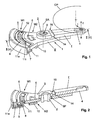
- the suspension arm actuator shown in Figs. 1 and 2 which is provided for an optical scanning device, not illustrated, comprises a rigid and torsionally stiff suspension arm 1 which is made of polypropylene, is designed in the form of a two-arm lever, is provided with a bearing bush 2 in its center of gravity CG between the lever arms I and II, and is, by means of said bearing bush 2, mounted to a support 3, Fig. 5 , such that it can be pivoted about a pivot axis PA perpendicularly in relation to the suspension arm 1.
- the lever arm I supports an optical head 4 having a focal lens.
- the lever arm II supports printed coils 5 and 6 in a concentric arrangement in relation to the pivot axis PA, said coils 5 and 6 each being allocated to permanent magnets 7, 8, 9 and 10, wherein said permanent magnets 7 and 8 are arranged on the legs 11o and 11i of a yoke 11 with a U-shaped cross-section that is permanently attached to the support, said yoke 11 being formed concentrically in relation to the pivot axis PA.
- the shell-like magnet 7 is arranged on the inner side of the outer leg 11o and the shell-like magnet 8 on the inner side of the inner leg 11i, wherein the inner leg 11i serves as a magnetic yoke and projects into a recess 12 having the shape of a circular arc and formed on the end side of the lever arm II, said recess being surrounded by coil strands of the coil 5 on its upper and lower sides, said coil 5 constituting a focus coil.
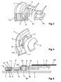
- a magnet 9 for field optimization is arranged on the yoke 11, in the region between the inner leg 11i and the shell-like magnet 7 and underneath the focus coil 5. Said magnet 9 is designed in the shape of a cubuid and is magnetized perpendicularly in relation to the shell-like magnets 7 and 8.
- the magnets 7, 8 and 9 and the focus coil 5 form a magnetic drive M1 initiating a pitching motion of the lever arm I with the optical head in a direction perpendicular in relation to the surface of an optical disk OD, the focusing direction f, said optical disk OD being indicated in Fig. 1 , wherein the magnets 8 and 9 serve for field optimization.
- the magnet 10 and the coil 6, a tracking coil, allocated there to form a magnetic drive M2 initiating a swivel motion of the suspension arm 1 in a pivot plane extending in parallel to the disk OD and, at the same time, in a radial direction in relation to the disk OD, tracking direction t.
- the magnets 7-10 advantageously Neodymium magnets or any other rare earth magnet may be used.
- the yoke 11 for example soft iron is used.
- Figs. 2 to 4 illustrate the arrangement and formation of the magnets 7 to 10, while Figs. 2 and 3 illustrate the arrangement of the printed coils 5 and 6. In particular, Figs. 3 and 4 show the arrangement and formation of the field optimization magnet 9 which is allocated to the focus coil 5.
- Fig. 5 shows the suspension arm actuator on the support 3 in a sectional view taken along V - V and, simultaneously, the formation of the suspension arm 1.
- a pivot pin 13 is permanently arranged on the support 3, with the suspension arm 1 being pivoted to said pivot pin 13 by means of the bearing bush 2 which is arranged on the lever arm I in a non-rotatable manner.
- the lever arm I comprises an elastically bendable region 14.
- the lever arm II is securely connected to said lever arm I in the region between the optical head 4 and the region 14, is held exclusively in said region and is, thus, freely suspended up to its edge region 15 on that side of the bendable region 14 that is facing away from the head 4.
- the region 14 is considerably reduced as compared with the thickness of this lever arm I while being designed in its thickness such that the first magnetic drive M1 moves the head-sided part of the otherwise rigid lever arm I in focusing direction f once the lever arm II is loaded.
- the secure connection of the two lever arms I and II is also used to initiate the swivel motion of the lever arm I about the pivot axis PA and, thus, to initiate a swivel motion of the entire suspension arm 1, wherein said swivel motion of the lever arm I about the pivot axis PA results from a swivel motion of the lever arm II caused by the second magnetic drive M2.
- the arrangement of the lever arm II is characterized by a play PL in relation to the bearing bush 2, with the result that this lever arm is freely suspended.
- the optical disk OD which is allocated to the suspension arm 1 and the head 4 thereof is arranged in parallel to said suspension arm 1.
- a swivel motion of the suspension arm 1 about the pivot axis PA causes the head 4 to be moved in radial direction relative to the disk OD, see Fig. 1 , tracking direction t. Focusing of a specific point on the disk OD is achieved through a motion of the lever arm II and, thus, of the optical head 4 in focusing direction f and perpendicularly in relation to the tracking direction t, with the magnets 8 and 9 providing for a sensitivity which is increased by up to 20 percent.
Landscapes
- Optical Recording Or Reproduction (AREA)
- Moving Of Heads (AREA)
- Optical Head (AREA)
Applications Claiming Priority (1)
| Application Number | Priority Date | Filing Date | Title |
|---|---|---|---|
| DE102007042291A DE102007042291A1 (de) | 2007-09-06 | 2007-09-06 | Schwingarm-Aktuator für eine Abtasteinrichtung |
Publications (2)
| Publication Number | Publication Date |
|---|---|
| EP2034474A1 true EP2034474A1 (fr) | 2009-03-11 |
| EP2034474B1 EP2034474B1 (fr) | 2013-06-12 |
Family
ID=39790889
Family Applications (1)
| Application Number | Title | Priority Date | Filing Date |
|---|---|---|---|
| EP08305496.5A Not-in-force EP2034474B1 (fr) | 2007-09-06 | 2008-08-22 | Actionneur de bras de suspension pour un dispositif de balayage |
Country Status (6)
| Country | Link |
|---|---|
| US (1) | US8392937B2 (fr) |
| EP (1) | EP2034474B1 (fr) |
| JP (1) | JP4923013B2 (fr) |
| KR (1) | KR101426391B1 (fr) |
| CN (1) | CN101383164B (fr) |
| DE (1) | DE102007042291A1 (fr) |
Families Citing this family (2)
| Publication number | Priority date | Publication date | Assignee | Title |
|---|---|---|---|---|
| DE102006026315A1 (de) * | 2006-06-02 | 2007-12-06 | Deutsche Thomson Ohg | Schwingarm-Aktuator für eine Abtasteinrichtung |
| EP2073201A1 (fr) * | 2007-12-21 | 2009-06-24 | Deutsche Thomson OHG | Actionneur à bras oscillant pour un dispositif de palpage |
Citations (6)
| Publication number | Priority date | Publication date | Assignee | Title |
|---|---|---|---|---|
| EP0400570A2 (fr) | 1989-05-30 | 1990-12-05 | Kabushiki Kaisha Toshiba | Système optique pour le traitement des informations |
| JPH05128580A (ja) | 1991-11-07 | 1993-05-25 | Hitachi Ltd | 光学式ヘツド装置 |
| US20040148619A1 (en) | 2003-01-23 | 2004-07-29 | Samsung Electronics Co., Ltd. | Optical Actuator |
| KR20040108029A (ko) * | 2003-06-16 | 2004-12-23 | 엘지전자 주식회사 | 광기록재생기의 포커싱 제어장치 |
| US20070121436A1 (en) * | 2005-11-25 | 2007-05-31 | Shigeo Nakamura | Optical disc drive |
| WO2007131877A1 (fr) * | 2006-05-13 | 2007-11-22 | Thomson Licensing S.A. | Actionneur de bras de suspension |
Family Cites Families (9)
| Publication number | Priority date | Publication date | Assignee | Title |
|---|---|---|---|---|
| DE388344C (de) | 1922-07-31 | 1924-01-11 | Albert Koch Akt Ges | Verfahren zur Herstellung von Zellstoff aus Fasertorf |
| JPS56170537U (fr) | 1980-05-16 | 1981-12-16 | ||
| JPH076372A (ja) * | 1993-06-21 | 1995-01-10 | Matsushita Electric Ind Co Ltd | 光ピックアップ装置およびそのフォーカス制御方法 |
| KR950020658A (ko) * | 1993-12-07 | 1995-07-24 | 새끼자와 다다시 | 자기디스크장치 |
| JP3519804B2 (ja) * | 1994-11-10 | 2004-04-19 | オリンパス株式会社 | 光ピックアップ装置 |
| JPH09282689A (ja) * | 1996-04-10 | 1997-10-31 | Toshiba Corp | 光ピックアップヘッド装置 |
| SG120083A1 (en) * | 2001-11-28 | 2006-03-28 | Matsushita Electric Industrial Co Ltd | Disk storage apparatus and disk storage apparatus control method |
| KR100493056B1 (ko) * | 2003-03-15 | 2005-06-02 | 삼성전자주식회사 | 광픽업 액츄에이터 |
| US7540004B2 (en) * | 2004-12-08 | 2009-05-26 | Electronics And Telecommunications Research Institute | Ultra-small optical/magnetic head actuator with pivot hinge and Halbach magnet array |
-
2007
- 2007-09-06 DE DE102007042291A patent/DE102007042291A1/de not_active Withdrawn
-
2008
- 2008-08-07 US US12/221,895 patent/US8392937B2/en not_active Expired - Fee Related
- 2008-08-22 EP EP08305496.5A patent/EP2034474B1/fr not_active Not-in-force
- 2008-09-04 CN CN2008102137732A patent/CN101383164B/zh not_active Expired - Fee Related
- 2008-09-04 KR KR1020080087383A patent/KR101426391B1/ko not_active Expired - Fee Related
- 2008-09-08 JP JP2008230112A patent/JP4923013B2/ja not_active Expired - Fee Related
Patent Citations (7)
| Publication number | Priority date | Publication date | Assignee | Title |
|---|---|---|---|---|
| EP0400570A2 (fr) | 1989-05-30 | 1990-12-05 | Kabushiki Kaisha Toshiba | Système optique pour le traitement des informations |
| JPH05128580A (ja) | 1991-11-07 | 1993-05-25 | Hitachi Ltd | 光学式ヘツド装置 |
| US20040148619A1 (en) | 2003-01-23 | 2004-07-29 | Samsung Electronics Co., Ltd. | Optical Actuator |
| JP2004227760A (ja) | 2003-01-23 | 2004-08-12 | Samsung Electronics Co Ltd | 光ピックアップアクチュエータ |
| KR20040108029A (ko) * | 2003-06-16 | 2004-12-23 | 엘지전자 주식회사 | 광기록재생기의 포커싱 제어장치 |
| US20070121436A1 (en) * | 2005-11-25 | 2007-05-31 | Shigeo Nakamura | Optical disc drive |
| WO2007131877A1 (fr) * | 2006-05-13 | 2007-11-22 | Thomson Licensing S.A. | Actionneur de bras de suspension |
Also Published As
| Publication number | Publication date |
|---|---|
| KR101426391B1 (ko) | 2014-08-05 |
| US8392937B2 (en) | 2013-03-05 |
| EP2034474B1 (fr) | 2013-06-12 |
| KR20090026078A (ko) | 2009-03-11 |
| DE102007042291A1 (de) | 2009-03-12 |
| JP2009064545A (ja) | 2009-03-26 |
| CN101383164A (zh) | 2009-03-11 |
| US20090070795A1 (en) | 2009-03-12 |
| CN101383164B (zh) | 2012-02-08 |
| JP4923013B2 (ja) | 2012-04-25 |
Similar Documents
| Publication | Publication Date | Title |
|---|---|---|
| EP1316949A3 (fr) | Actionneur pour appareil de lecture optique | |
| US20020150002A1 (en) | Optical pickup and method of assembling the optical pickup | |
| EP2034474B1 (fr) | Actionneur de bras de suspension pour un dispositif de balayage | |
| US7540004B2 (en) | Ultra-small optical/magnetic head actuator with pivot hinge and Halbach magnet array | |
| US20010026404A1 (en) | Optical pick-up actuator | |
| US20090249380A1 (en) | Suspension Arm Actuator for a Scanning Device | |
| US20090174966A1 (en) | Swivel Arm Actuator for Multiple Directions of Movement | |
| US6175546B1 (en) | Curved-beam supporting structure for optical pickup actuators in optical disc drivers | |
| EP2073200B1 (fr) | Actionneur de bras de suspension pour un dispositif de balayage | |
| US6650508B2 (en) | Positioning mechanism for information storage apparatus and carriage | |
| EP1783760B1 (fr) | Appareil destiné à lire un support d'enregistrement optique et/ou à écrire sur ce dernier | |
| KR100548246B1 (ko) | 광디스크 드라이브의 렌즈 돌출형 액츄에이터 | |
| KR100473949B1 (ko) | 광픽업용 액츄에이터 | |
| JP4433974B2 (ja) | 対物レンズ駆動装置 | |
| JPH04285731A (ja) | 光ヘッドアクチュエータ | |
| JP2005092956A (ja) | 光ディスク装置 | |
| JP2009104707A (ja) | 対物レンズアクチュエータ、光ピックアップおよび光ディスク装置 | |
| WO2008065034A1 (fr) | Actionneur de bras de suspension à amortissement pour dispositif de balayage | |
| JP2007149324A (ja) | 光ディスクをスキャニングするためのスキャニング装置用のアクチュエータ | |
| JP2007149323A (ja) | 光スキャニング装置のためのアクチュエータ | |
| KR20080009316A (ko) | 디스크 드라이브용 광 픽업장치와 이 광 픽업장치를 구비한디스크 드라이브 | |
| EP2015297A2 (fr) | Actuateur avec ensemble à bras pivotant pour accéder à un support de stockage mobile et unité d'entrainement de disque comprenant cet actuateur | |
| JP2004310966A (ja) | 光ピックアップ装置のアクチュエーター,光ピックアップ装置,光ディスク装置および対物レンズの位置調整方法 | |
| JPH03127336A (ja) | 光ヘッド装置 | |
| JP2000067442A (ja) | 光ヘッドアクチュエ−タ |
Legal Events
| Date | Code | Title | Description |
|---|---|---|---|
| PUAI | Public reference made under article 153(3) epc to a published international application that has entered the european phase |
Free format text: ORIGINAL CODE: 0009012 |
|
| AK | Designated contracting states |
Kind code of ref document: A1 Designated state(s): AT BE BG CH CY CZ DE DK EE ES FI FR GB GR HR HU IE IS IT LI LT LU LV MC MT NL NO PL PT RO SE SI SK TR |
|
| AX | Request for extension of the european patent |
Extension state: AL BA MK RS |
|
| 17Q | First examination report despatched |
Effective date: 20090923 |
|
| 17P | Request for examination filed |
Effective date: 20090828 |
|
| AKX | Designation fees paid |
Designated state(s): DE FR GB |
|
| RAP1 | Party data changed (applicant data changed or rights of an application transferred) |
Owner name: THOMSON LICENSING |
|
| GRAP | Despatch of communication of intention to grant a patent |
Free format text: ORIGINAL CODE: EPIDOSNIGR1 |
|
| GRAS | Grant fee paid |
Free format text: ORIGINAL CODE: EPIDOSNIGR3 |
|
| GRAA | (expected) grant |
Free format text: ORIGINAL CODE: 0009210 |
|
| AK | Designated contracting states |
Kind code of ref document: B1 Designated state(s): DE FR GB |
|
| REG | Reference to a national code |
Ref country code: GB Ref legal event code: FG4D |
|
| REG | Reference to a national code |
Ref country code: DE Ref legal event code: R096 Ref document number: 602008025263 Country of ref document: DE Effective date: 20130808 |
|
| REG | Reference to a national code |
Ref country code: DE Ref legal event code: R084 Ref document number: 602008025263 Country of ref document: DE Effective date: 20130617 |
|
| PLBE | No opposition filed within time limit |
Free format text: ORIGINAL CODE: 0009261 |
|
| STAA | Information on the status of an ep patent application or granted ep patent |
Free format text: STATUS: NO OPPOSITION FILED WITHIN TIME LIMIT |
|
| 26N | No opposition filed |
Effective date: 20140313 |
|
| GBPC | Gb: european patent ceased through non-payment of renewal fee |
Effective date: 20130912 |
|
| REG | Reference to a national code |
Ref country code: DE Ref legal event code: R097 Ref document number: 602008025263 Country of ref document: DE Effective date: 20140313 |
|
| PG25 | Lapsed in a contracting state [announced via postgrant information from national office to epo] |
Ref country code: GB Free format text: LAPSE BECAUSE OF NON-PAYMENT OF DUE FEES Effective date: 20130912 |
|
| REG | Reference to a national code |
Ref country code: FR Ref legal event code: PLFP Year of fee payment: 8 |
|
| PGFP | Annual fee paid to national office [announced via postgrant information from national office to epo] |
Ref country code: DE Payment date: 20150827 Year of fee payment: 8 |
|
| PGFP | Annual fee paid to national office [announced via postgrant information from national office to epo] |
Ref country code: FR Payment date: 20150820 Year of fee payment: 8 |
|
| REG | Reference to a national code |
Ref country code: DE Ref legal event code: R119 Ref document number: 602008025263 Country of ref document: DE |
|
| REG | Reference to a national code |
Ref country code: FR Ref legal event code: ST Effective date: 20170428 |
|
| PG25 | Lapsed in a contracting state [announced via postgrant information from national office to epo] |
Ref country code: DE Free format text: LAPSE BECAUSE OF NON-PAYMENT OF DUE FEES Effective date: 20170301 Ref country code: FR Free format text: LAPSE BECAUSE OF NON-PAYMENT OF DUE FEES Effective date: 20160831 |