EP2034566A2 - Connexion à fiche photovoltaïque - Google Patents
Connexion à fiche photovoltaïque Download PDFInfo
- Publication number
- EP2034566A2 EP2034566A2 EP08015738A EP08015738A EP2034566A2 EP 2034566 A2 EP2034566 A2 EP 2034566A2 EP 08015738 A EP08015738 A EP 08015738A EP 08015738 A EP08015738 A EP 08015738A EP 2034566 A2 EP2034566 A2 EP 2034566A2
- Authority
- EP
- European Patent Office
- Prior art keywords
- contact
- plug
- contact carrier
- socket
- carrier
- Prior art date
- Legal status (The legal status is an assumption and is not a legal conclusion. Google has not performed a legal analysis and makes no representation as to the accuracy of the status listed.)
- Withdrawn
Links
Images






Classifications
-
- H—ELECTRICITY
- H01—ELECTRIC ELEMENTS
- H01R—ELECTRICALLY-CONDUCTIVE CONNECTIONS; STRUCTURAL ASSOCIATIONS OF A PLURALITY OF MUTUALLY-INSULATED ELECTRICAL CONNECTING ELEMENTS; COUPLING DEVICES; CURRENT COLLECTORS
- H01R13/00—Details of coupling devices of the kinds covered by groups H01R12/70 or H01R24/00 - H01R33/00
- H01R13/46—Bases; Cases
- H01R13/52—Dustproof, splashproof, drip-proof, waterproof, or flameproof cases
- H01R13/5205—Sealing means between cable and housing, e.g. grommet
-
- H—ELECTRICITY
- H01—ELECTRIC ELEMENTS
- H01R—ELECTRICALLY-CONDUCTIVE CONNECTIONS; STRUCTURAL ASSOCIATIONS OF A PLURALITY OF MUTUALLY-INSULATED ELECTRICAL CONNECTING ELEMENTS; COUPLING DEVICES; CURRENT COLLECTORS
- H01R13/00—Details of coupling devices of the kinds covered by groups H01R12/70 or H01R24/00 - H01R33/00
- H01R13/58—Means for relieving strain on wire connection, e.g. cord grip, for avoiding loosening of connections between wires and terminals within a coupling device terminating a cable
- H01R13/5804—Means for relieving strain on wire connection, e.g. cord grip, for avoiding loosening of connections between wires and terminals within a coupling device terminating a cable comprising a separate cable clamping part
- H01R13/5812—Means for relieving strain on wire connection, e.g. cord grip, for avoiding loosening of connections between wires and terminals within a coupling device terminating a cable comprising a separate cable clamping part the cable clamping being achieved by mounting the separate part on the housing of the coupling device
-
- H—ELECTRICITY
- H01—ELECTRIC ELEMENTS
- H01R—ELECTRICALLY-CONDUCTIVE CONNECTIONS; STRUCTURAL ASSOCIATIONS OF A PLURALITY OF MUTUALLY-INSULATED ELECTRICAL CONNECTING ELEMENTS; COUPLING DEVICES; CURRENT COLLECTORS
- H01R13/00—Details of coupling devices of the kinds covered by groups H01R12/70 or H01R24/00 - H01R33/00
- H01R13/02—Contact members
- H01R13/04—Pins or blades for co-operation with sockets
- H01R13/05—Resilient pins or blades
- H01R13/052—Resilient pins or blades co-operating with sockets having a circular transverse section
-
- H—ELECTRICITY
- H01—ELECTRIC ELEMENTS
- H01R—ELECTRICALLY-CONDUCTIVE CONNECTIONS; STRUCTURAL ASSOCIATIONS OF A PLURALITY OF MUTUALLY-INSULATED ELECTRICAL CONNECTING ELEMENTS; COUPLING DEVICES; CURRENT COLLECTORS
- H01R13/00—Details of coupling devices of the kinds covered by groups H01R12/70 or H01R24/00 - H01R33/00
- H01R13/02—Contact members
- H01R13/10—Sockets for co-operation with pins or blades
- H01R13/11—Resilient sockets
- H01R13/111—Resilient sockets co-operating with pins having a circular transverse section
-
- H—ELECTRICITY
- H01—ELECTRIC ELEMENTS
- H01R—ELECTRICALLY-CONDUCTIVE CONNECTIONS; STRUCTURAL ASSOCIATIONS OF A PLURALITY OF MUTUALLY-INSULATED ELECTRICAL CONNECTING ELEMENTS; COUPLING DEVICES; CURRENT COLLECTORS
- H01R13/00—Details of coupling devices of the kinds covered by groups H01R12/70 or H01R24/00 - H01R33/00
- H01R13/44—Means for preventing access to live contacts
-
- H—ELECTRICITY
- H01—ELECTRIC ELEMENTS
- H01R—ELECTRICALLY-CONDUCTIVE CONNECTIONS; STRUCTURAL ASSOCIATIONS OF A PLURALITY OF MUTUALLY-INSULATED ELECTRICAL CONNECTING ELEMENTS; COUPLING DEVICES; CURRENT COLLECTORS
- H01R13/00—Details of coupling devices of the kinds covered by groups H01R12/70 or H01R24/00 - H01R33/00
- H01R13/46—Bases; Cases
- H01R13/52—Dustproof, splashproof, drip-proof, waterproof, or flameproof cases
- H01R13/5219—Sealing means between coupling parts, e.g. interfacial seal
-
- H—ELECTRICITY
- H01—ELECTRIC ELEMENTS
- H01R—ELECTRICALLY-CONDUCTIVE CONNECTIONS; STRUCTURAL ASSOCIATIONS OF A PLURALITY OF MUTUALLY-INSULATED ELECTRICAL CONNECTING ELEMENTS; COUPLING DEVICES; CURRENT COLLECTORS
- H01R13/00—Details of coupling devices of the kinds covered by groups H01R12/70 or H01R24/00 - H01R33/00
- H01R13/62—Means for facilitating engagement or disengagement of coupling parts or for holding them in engagement
- H01R13/627—Snap or like fastening
- H01R13/6271—Latching means integral with the housing
- H01R13/6273—Latching means integral with the housing comprising two latching arms
-
- H—ELECTRICITY
- H01—ELECTRIC ELEMENTS
- H01R—ELECTRICALLY-CONDUCTIVE CONNECTIONS; STRUCTURAL ASSOCIATIONS OF A PLURALITY OF MUTUALLY-INSULATED ELECTRICAL CONNECTING ELEMENTS; COUPLING DEVICES; CURRENT COLLECTORS
- H01R2101/00—One pole
-
- H—ELECTRICITY
- H01—ELECTRIC ELEMENTS
- H01R—ELECTRICALLY-CONDUCTIVE CONNECTIONS; STRUCTURAL ASSOCIATIONS OF A PLURALITY OF MUTUALLY-INSULATED ELECTRICAL CONNECTING ELEMENTS; COUPLING DEVICES; CURRENT COLLECTORS
- H01R43/00—Apparatus or processes specially adapted for manufacturing, assembling, maintaining, or repairing of line connectors or current collectors or for joining electric conductors
- H01R43/16—Apparatus or processes specially adapted for manufacturing, assembling, maintaining, or repairing of line connectors or current collectors or for joining electric conductors for manufacturing contact members, e.g. by punching and by bending
Definitions
- the invention relates to a connector, preferably for outdoor use of solar systems for interconnecting solar panels, according to the features of the respective preamble of the independent claims.
- the invention is therefore based on the object to eliminate these disadvantages and to provide a better connector.
- the invention relates to compact connector pairs for the photovoltaic, which are as rational as possible both in Umspritztechnik and freely assembled and of course are compatible with each plugged.
- the plug has a contact carrier, in which a contact pin is arranged and fixed, wherein the contact carrier end receives a cable sealing ring with a strain relief claw, wherein the strain relief claw interacts with a pressure screw to tensile and compressive forces acting on a cable act to decouple from the contact pin.
- the box is formed, which also has a contact carrier, in which a contact socket is arranged and fixed, wherein the contact carrier end receives a cable sealing ring with a strain relief claw, the strain relief claw interacts with a pressure screw to tensile and compressive forces acting on a cable act to decouple from the contact socket.
- strain relief claw and pressure screw has the advantage that both plug and socket are sealed at the ends in the cable outlet area.
- a seal between the contact carrier of the plug and the contact carrier of the can is still provided, this seal is preferably formed as an O-ring.
- the seal with production of the contact carrier of the plug and / or the box in a two-component injection molding process will be produced. This has the advantage that in such a case, the seal is arranged captively on the contact carrier of the plug or the box.
- the contact carrier of the plug or the box is formed by an overmolded plastic, wherein in the case of the plug, the contact pin and in the case of the socket the contact socket is determined by the encapsulation in the respective contact carrier.
- the contact carrier of the plug or the socket is also formed again by an overmolded plastic, however, the contact pin at the plug or the contact socket at the can is fixed non-positively in the contact carrier. This can be done for example by pressing, clipping or the like. Gluing is also possible.
- the contact pin of the plug or the female contact of the box is formed as a punch-roll contact. This has the advantage that the respective contact in the desired form can be produced quickly and inexpensively.
- the contact carrier of the plug latching openings and the contact carrier of the box has latching hooks (or vice versa), wherein the latching openings are designed so small on the plug that the latching hooks on the box can not be solved by finger pressure.
- the outer surfaces of the locking lugs of the latching hooks in the locked state are recessed by a corresponding amount relative to the outer surface of the associated contact carrier.
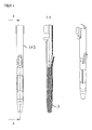
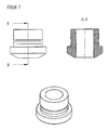
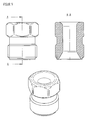
- FIGS. 1 to 3 show, as far as shown in detail, the connector 1, which consist of a plug 1.1 and a socket 1.2.
- the connector 1 which consist of a plug 1.1 and a socket 1.2.
- FIG. 1 is shown in section AA the interior of this composite connector, reference being made to the following figures for further details.
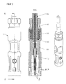
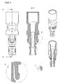
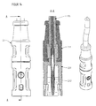
- the Figures 2 and 3 show in detail the plug 1.1, wherein the plug 1.1 has a contact carrier 1.1.1 by a contact pin 1.1.2 is arranged and fixed, wherein the contact carrier 1.1.1 ends a cable sealing ring 1.1.3 with a strain relief claw 1.1.4 receives, wherein the strain relief claw 1.1.4 cooperates with a pressure screw 1.1.5 to decouple tensile and compressive forces acting on a cable 1.1.6, from the contact pin 1.1.2. With 1.1.7 latching openings are called, which interact with not shown here locking hooks of the box 1.2.
- FIG. 3 shows details of the connector 1.1, in particular the details in the view B and in the view C is to be pointed.
- Detail view B deals with the configuration of an insertion region for the contact pin 1.1.2, a paragraph shown in detail view B being provided in this region.
- the latching openings are 1.1.7 recognizable, wherein in the insertion direction of the contact carrier is formed starting from the Einrastötechnisch 1.1.7 conically widening to facilitate mating plug and socket.
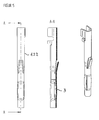
- FIG. 4 shows a specific embodiment of the contact pin 1.1.2, wherein in FIG. 5 the specific embodiment of a contact socket for the can is shown.
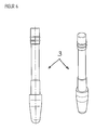
- FIG. 6 Another important and essential element for the connector according to the invention is in the form of a contact protection 3 in FIG. 6 shown.
- the in FIG. 6 contact protection 3 shown is inserted into the contact pin 1.1.2 such that in the interior of the contact carrier contact surfaces of the contact pin 1.1.2 remain free for the contact socket 1.2.1, but the end, ie forward towards the plug-in area, a contact protection is given.
- the contact protection 3 made of an electrically non-conductive material, such. As a plastic formed.
- the contact protection 3 in FIG. 5 present, in which case the contact protection 3 is arranged on the outer surface of the contact socket 1.2.1 in order to avoid accidental contact with the arranged in the contact carrier 1.2.1 of the socket 1.2 contact socket 1.2.1.
- These aforementioned elements are all preferably made of plastic, wherein they may be formed of the same or different plastics, wherein Preferably, the strain relief claw 1.1.4 and the pressure screw 1.1.5 are formed of a rigid plastic, wherein the cable sealing ring 1.1.3 preferably consists of an elastically deformable plastic.
- a radially circumferential seal 1.2.3 is present in the mating region of the box 1.2.
- FIG. 12 is a detail of a contact socket 1.2.1 shown, which is advantageously designed as a punch-roll contact.
- contact wings are present at the end, with which an electrical conductor of the cable 1.1.6 is crimped on the contact.
- protruding and outwardly facing wings are provided, with which insertion of the contact pin is facilitated in the contact socket.
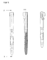
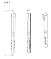
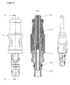
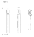
- FIGS. 13 to 18 are alternative embodiments of the connector according to the invention, for which also apply the features of the claims, shown in FIG FIG. 13 a connector 2, consisting of plug 2.1 and 2.2 socket with its inner life (section AA) can be seen.
- FIG. 14 shows the connector 2.1, wherein in this embodiment, the contact carrier is divided into two and of the two parts 2.1.1, which receives the contact pin 2.1.2, and the end-side part 2.1.3, from which the cable is led out 1.1.6, is formed ,
- the corresponding contact pin, also provided with the contact protection 3, is in FIG. 15 shown.
- the analog contact socket is in FIG. 16 , also provided with a shock protection, shown, wherein the associated with the contact socket 2.2 in FIG. 17 is shown.
- this can 2.2 has a two-part contact carrier 2.2.1 with contact socket 2.2.2, the contact carrier part 2.2.1 being connected to the further part 2.2.3, from which the cable 1.1.6 is led out.
- the contact carrier parts 2.1.1 and 2.1.3 of the plug 2.1 or the contact carrier parts 2.2.1 and 2.2.3 of the can 2.2 are preferably produced in a two-component injection molding process, wherein the respective contacts 2.1.2 and 2.2.2, which are attached and electrically contacted at the end of the cable 1.1.6, are inserted into the injection molding tool, wherein subsequently with two different plastics, the encapsulation takes place, so that the above-mentioned contact carrier parts are formed.
- the present solution works with electrical contacts - preferably with stamped rolling contacts - on the one hand are on the one hand as cost-effective, and on the other hand can be used by slight changes both in overmolded and in freely attachable connectors (for The respective snap-in elements on the contacts in the tool are not executed by overmolding, see FIGS. 4 . 5 . 12 . 15 . 16 and 18 ).
- the direct encapsulation in the FIGS. 15 and 18 shown contacts is significantly facilitated or even made possible by the contact pin springy and the contact socket is made rigid.
- the contact pin from the FIG. 15 is used within the pin, located behind the spring blades end face of the correspondingly long designed Berstoffschutzes from FIG.
- molded connectors can be used as in the FIG. 14 or cans as in the FIG. 17 in conjunction with a 2K injection machine semi-automatic or fully automatic (2K means two components, ie two different plastics).
- Plug and socket are locked in the assembled state so that a subsequent release is possible only with the help of a corresponding tool.
- the latching openings on the plugs (see Figures 2 . 3 and 14 ) designed so small that the snap hooks on the cans (see Figures 10 . 11 and 17 ) can not be solved by finger pressure.
- this also the outer surfaces of the locking lugs of the locking hooks in the locked state must be kept deepened by a corresponding amount relative to the outer surface.
- the latching openings of the plug ( Figures 2 . 3 and 14 ) integrated in the wall of the actual plug-in space (in commercially available similar solutions, such openings are arranged as tabs on the wall of the plug-in space).
Landscapes
- Connector Housings Or Holding Contact Members (AREA)
- Details Of Connecting Devices For Male And Female Coupling (AREA)
Applications Claiming Priority (1)
| Application Number | Priority Date | Filing Date | Title |
|---|---|---|---|
| DE102007041989 | 2007-09-05 |
Publications (2)
| Publication Number | Publication Date |
|---|---|
| EP2034566A2 true EP2034566A2 (fr) | 2009-03-11 |
| EP2034566A3 EP2034566A3 (fr) | 2009-12-30 |
Family
ID=40177823
Family Applications (1)
| Application Number | Title | Priority Date | Filing Date |
|---|---|---|---|
| EP08015738A Withdrawn EP2034566A3 (fr) | 2007-09-05 | 2008-09-05 | Connexion à fiche photovoltaïque |
Country Status (3)
| Country | Link |
|---|---|
| US (1) | US20090075525A1 (fr) |
| EP (1) | EP2034566A3 (fr) |
| DE (1) | DE102008045801A1 (fr) |
Cited By (6)
| Publication number | Priority date | Publication date | Assignee | Title |
|---|---|---|---|---|
| WO2011151392A1 (fr) * | 2010-06-04 | 2011-12-08 | Multi-Holding Ag | Boîtier de connecteur |
| EP2500989A4 (fr) * | 2009-11-13 | 2014-07-02 | Join Co Ltd | Connecteur |
| WO2014150807A1 (fr) | 2013-03-15 | 2014-09-25 | Aqua Products, Inc. | Raccord pivotant imperméable séparable |
| EP3389146A1 (fr) * | 2017-04-11 | 2018-10-17 | Yazaki Europe Ltd. | Agencement de connexion électrique |
| CN110429422A (zh) * | 2019-06-24 | 2019-11-08 | 江苏弘策机电科技有限公司 | 一种防潮型接线端子 |
| EP3723208A1 (fr) * | 2019-04-12 | 2020-10-14 | Aptiv Technologies Limited | Procédé de fabrication d'une borne de puissance mâle et borne de puissance mâle |
Families Citing this family (10)
| Publication number | Priority date | Publication date | Assignee | Title |
|---|---|---|---|---|
| DE102009019860A1 (de) | 2009-05-06 | 2010-11-18 | Alexander POPA c/o APO Consulting & Sales | Stecker für Photovoltaikanlagen |
| CN102474040A (zh) * | 2009-07-10 | 2012-05-23 | 阿萨赫百斯特贝斯有限公司 | 包胶的安全且防水的光伏连接器 |
| WO2011147120A1 (fr) * | 2010-05-28 | 2011-12-01 | Lv Jikun | Connecteur de câble pour cellule photovoltaïque |
| ES2350556B1 (es) * | 2010-07-28 | 2012-01-30 | Incaelec, S.L.U. | Sistema de conexión para cables eléctricos, particularmente para cables eléctricos de instalaciones fotovoltáicas. |
| DE202010011857U1 (de) | 2010-08-25 | 2010-10-28 | Ccs Cable Connector Systems Gmbh | Stecker, insbesondere Photovoltaikstecker |
| DE102010053023A1 (de) | 2010-12-02 | 2012-06-06 | Andrea Bäumer | Steckverbinder für Photovoltaik |
| EP2573878A1 (fr) | 2011-09-22 | 2013-03-27 | Lapp Engineering & Co. | Elément de connexion pour un connecteur à fiche |
| US20140099810A1 (en) * | 2012-08-27 | 2014-04-10 | Eco Power Design LLC | Solar system wiring connectors and methods for secured connection of wiring in an outdoor environment |
| US11469536B2 (en) * | 2020-04-01 | 2022-10-11 | Sony Interactive Entertainment Inc. | Shape of connector shells of cables |
| CN113193831A (zh) * | 2021-04-15 | 2021-07-30 | 力维兴电子(深圳)有限公司 | 一种避免空隙的安全型地面光伏用铜铝连接器 |
Family Cites Families (13)
| Publication number | Priority date | Publication date | Assignee | Title |
|---|---|---|---|---|
| US3624591A (en) * | 1970-06-01 | 1971-11-30 | Harry P Buberniak | Electrical cable connector assembly |
| US4927382A (en) * | 1987-11-03 | 1990-05-22 | Siemens Aktiengesellschaft | Electrical function group for a vehicle |
| JP2000040547A (ja) * | 1998-07-22 | 2000-02-08 | Sumitomo Wiring Syst Ltd | 電気接続用コネクタ |
| DE10062476A1 (de) * | 2000-12-14 | 2002-06-20 | Aloys Mennekes Anlagengmbh & C | Anschlussvorrichtung für insbesondere mehradrige Elektrokabel |
| DE10146329B4 (de) * | 2001-09-20 | 2009-02-26 | Neutrik Aktiengesellschaft | Elektrischer Kabelstecker |
| DE10215194A1 (de) * | 2002-04-05 | 2003-10-16 | Multi Holding Ag Allschwil | Steckverbindung für den Ausseneinsatz, insbesondere für den elektrichen Anschluss von Solarpanels |
| US6817897B2 (en) * | 2002-10-22 | 2004-11-16 | Alexander B. Chee | End connector for coaxial cable |
| DE20217500U1 (de) * | 2002-11-13 | 2003-02-06 | Anton Hummel Verwaltungs Gmbh, 79183 Waldkirch | Kabelanschluß mit einer Aderaufnahme |
| JP2006513543A (ja) * | 2003-01-23 | 2006-04-20 | ヒルシュマン エレクトロニクス ゲゼルシャフト ミット ベシュレンクテル ハフツング ウント コンパニー コマンディートゲゼルシャフト | ケーブル差込み接続器 |
| EP1467441A3 (fr) * | 2003-01-23 | 2005-08-31 | Hirschmann Electronics GmbH & Co. KG | Connecteur pour un branchement rapide à technique de pince de serrage |
| JP2006147189A (ja) * | 2004-11-16 | 2006-06-08 | Sumitomo Wiring Syst Ltd | 太陽電池モジュール用コネクタ |
| CN101253656B (zh) * | 2005-06-27 | 2012-01-11 | 普罗布兰德国际有限公司 | 用于同轴电缆的端部连接器 |
| US7364462B2 (en) * | 2006-05-02 | 2008-04-29 | Michael Holland | Compression ring for coaxial cable connector |
-
2008
- 2008-09-05 EP EP08015738A patent/EP2034566A3/fr not_active Withdrawn
- 2008-09-05 DE DE102008045801A patent/DE102008045801A1/de not_active Withdrawn
- 2008-09-05 US US12/204,899 patent/US20090075525A1/en not_active Abandoned
Cited By (12)
| Publication number | Priority date | Publication date | Assignee | Title |
|---|---|---|---|---|
| EP2500989A4 (fr) * | 2009-11-13 | 2014-07-02 | Join Co Ltd | Connecteur |
| WO2011151392A1 (fr) * | 2010-06-04 | 2011-12-08 | Multi-Holding Ag | Boîtier de connecteur |
| CN102934290A (zh) * | 2010-06-04 | 2013-02-13 | 马尔遆公开股份有限公司 | 插塞式连接器壳体 |
| WO2014150807A1 (fr) | 2013-03-15 | 2014-09-25 | Aqua Products, Inc. | Raccord pivotant imperméable séparable |
| EP2973878A4 (fr) * | 2013-03-15 | 2016-11-09 | Aqua Products Inc | Raccord pivotant imperméable séparable |
| EP3389146A1 (fr) * | 2017-04-11 | 2018-10-17 | Yazaki Europe Ltd. | Agencement de connexion électrique |
| JP2018200864A (ja) * | 2017-04-11 | 2018-12-20 | ヤザキ・ヨーロッパ・リミテッド | 電気接続装置 |
| US10205274B2 (en) | 2017-04-11 | 2019-02-12 | Yazaki Europe Ltd. | Electronic connection arrangement |
| EP3723208A1 (fr) * | 2019-04-12 | 2020-10-14 | Aptiv Technologies Limited | Procédé de fabrication d'une borne de puissance mâle et borne de puissance mâle |
| US11133636B2 (en) | 2019-04-12 | 2021-09-28 | Aptiv Technologies Limited | Method for manufacturing a male power terminal, and male power terminal |
| CN110429422A (zh) * | 2019-06-24 | 2019-11-08 | 江苏弘策机电科技有限公司 | 一种防潮型接线端子 |
| CN110429422B (zh) * | 2019-06-24 | 2021-01-29 | 江苏弘策机电科技有限公司 | 一种防潮型接线端子 |
Also Published As
| Publication number | Publication date |
|---|---|
| EP2034566A3 (fr) | 2009-12-30 |
| US20090075525A1 (en) | 2009-03-19 |
| DE102008045801A1 (de) | 2009-03-12 |
Similar Documents
| Publication | Publication Date | Title |
|---|---|---|
| DE102008045801A1 (de) | Photovoltaik-Steckverbindung | |
| EP2777096B1 (fr) | Unité de connexion à fiches multipolaire pour systèmes électriques triphasés | |
| DE102013213336B4 (de) | Elektrischer steckverbinder, ladedose und steckverbindersystem für ein elektro- oder hybridfahrzeug | |
| EP2182592B1 (fr) | Connecteur à fiches | |
| EP3895256B1 (fr) | Connecteur enfichable rond présentant un dispositif de verrouillage | |
| DE202012013480U1 (de) | Elektrische Wanddurchführung für Solaranlagen | |
| WO2018192962A1 (fr) | Assemblage d'une pièce de connecteur à fiches avec insert de contact et élément de mise à la terre | |
| WO2004097995A1 (fr) | Connexion a fiches electrique | |
| DE69911515T2 (de) | Elektrischer Steckverbinder mit Verrieglungsring | |
| DE102012104857B4 (de) | Elektrische Steckverbindung | |
| EP2515387B1 (fr) | Prise mâle | |
| DE102017003296B3 (de) | Steckverbinder und Verfahren zur Herstellung einer Steckverbindung | |
| DE102012212430B4 (de) | Verbindungseinrichtung für Leistungshalbleitereinrichtung mit dichtem Steckverbinder, Leistungshalbleitereinrichtung mit einer solchen Verbindungseinrichtung und Verfahren zur Ausbildung einer Verbindung mit einer solchen Verbindungseinrichtung | |
| DE102008059000B4 (de) | Elektrisches Steckverbindersystem | |
| DE202008005493U1 (de) | Steckverbindung für die Außenanwendung, insbesondere für Solarpanels | |
| DE112012003582T5 (de) | Verbinder und Bedeckungselement für diesen | |
| DE102011056556A1 (de) | Gehäuse für einen optischen oder elektrischen Steckverbinder zur Verwendung mit und ohne Hebel sowie Baukasten mit einem solchen Gehäuse | |
| DE10215194A1 (de) | Steckverbindung für den Ausseneinsatz, insbesondere für den elektrichen Anschluss von Solarpanels | |
| DE102018107886B4 (de) | Steckverbindersystem mit einem bistabilen Element | |
| WO2020208075A1 (fr) | Fiche de décharge pour un accumulateur d'une bicyclette électrique | |
| DE102012105901A1 (de) | Zugentlastungseinheit für einen elektrischen Steckverbinder und Gerätegehäuse | |
| EP3176882B1 (fr) | Élément de couplage ayant une conduite électrique raccordée | |
| EP2587595A1 (fr) | Connexion à fiche et procédé d'actionnement d'une connexion à fiche pour applications haute tension | |
| DE2707254C2 (de) | Elektrische Kupplung | |
| EP2164138B1 (fr) | Coupe arrière dans un support de contact d'un connecteur à fiches du côté du capteur |
Legal Events
| Date | Code | Title | Description |
|---|---|---|---|
| PUAI | Public reference made under article 153(3) epc to a published international application that has entered the european phase |
Free format text: ORIGINAL CODE: 0009012 |
|
| AK | Designated contracting states |
Kind code of ref document: A2 Designated state(s): AT BE BG CH CY CZ DE DK EE ES FI FR GB GR HR HU IE IS IT LI LT LU LV MC MT NL NO PL PT RO SE SI SK TR |
|
| AX | Request for extension of the european patent |
Extension state: AL BA MK RS |
|
| PUAL | Search report despatched |
Free format text: ORIGINAL CODE: 0009013 |
|
| AK | Designated contracting states |
Kind code of ref document: A3 Designated state(s): AT BE BG CH CY CZ DE DK EE ES FI FR GB GR HR HU IE IS IT LI LT LU LV MC MT NL NO PL PT RO SE SI SK TR |
|
| AX | Request for extension of the european patent |
Extension state: AL BA MK RS |
|
| RIC1 | Information provided on ipc code assigned before grant |
Ipc: H01R 24/00 20060101ALI20091123BHEP Ipc: H01R 13/58 20060101ALI20091123BHEP Ipc: H01R 13/52 20060101AFI20090109BHEP |
|
| AKY | No designation fees paid | ||
| STAA | Information on the status of an ep patent application or granted ep patent |
Free format text: STATUS: THE APPLICATION IS DEEMED TO BE WITHDRAWN |
|
| 18D | Application deemed to be withdrawn |
Effective date: 20100701 |
|
| REG | Reference to a national code |
Ref country code: DE Ref legal event code: 8566 |