EP2034732A1 - Digitalausstrahlungsempfänger - Google Patents
Digitalausstrahlungsempfänger Download PDFInfo
- Publication number
- EP2034732A1 EP2034732A1 EP07741207A EP07741207A EP2034732A1 EP 2034732 A1 EP2034732 A1 EP 2034732A1 EP 07741207 A EP07741207 A EP 07741207A EP 07741207 A EP07741207 A EP 07741207A EP 2034732 A1 EP2034732 A1 EP 2034732A1
- Authority
- EP
- European Patent Office
- Prior art keywords
- service
- hierarchy
- services
- broadcasting
- receivable
- Prior art date
- Legal status (The legal status is an assumption and is not a legal conclusion. Google has not performed a legal analysis and makes no representation as to the accuracy of the status listed.)
- Withdrawn
Links
Images





Classifications
-
- H—ELECTRICITY
- H04—ELECTRIC COMMUNICATION TECHNIQUE
- H04H—BROADCAST COMMUNICATION
- H04H60/00—Arrangements for broadcast applications with a direct linking to broadcast information or broadcast space-time; Broadcast-related systems
- H04H60/35—Arrangements for identifying or recognising characteristics with a direct linkage to broadcast information or to broadcast space-time, e.g. for identifying broadcast stations or for identifying users
- H04H60/38—Arrangements for identifying or recognising characteristics with a direct linkage to broadcast information or to broadcast space-time, e.g. for identifying broadcast stations or for identifying users for identifying broadcast time or space
- H04H60/39—Arrangements for identifying or recognising characteristics with a direct linkage to broadcast information or to broadcast space-time, e.g. for identifying broadcast stations or for identifying users for identifying broadcast time or space for identifying broadcast space-time
-
- H—ELECTRICITY
- H04—ELECTRIC COMMUNICATION TECHNIQUE
- H04H—BROADCAST COMMUNICATION
- H04H60/00—Arrangements for broadcast applications with a direct linking to broadcast information or broadcast space-time; Broadcast-related systems
- H04H60/35—Arrangements for identifying or recognising characteristics with a direct linkage to broadcast information or to broadcast space-time, e.g. for identifying broadcast stations or for identifying users
- H04H60/38—Arrangements for identifying or recognising characteristics with a direct linkage to broadcast information or to broadcast space-time, e.g. for identifying broadcast stations or for identifying users for identifying broadcast time or space
- H04H60/41—Arrangements for identifying or recognising characteristics with a direct linkage to broadcast information or to broadcast space-time, e.g. for identifying broadcast stations or for identifying users for identifying broadcast time or space for identifying broadcast space, i.e. broadcast channels, broadcast stations or broadcast areas
-
- H—ELECTRICITY
- H04—ELECTRIC COMMUNICATION TECHNIQUE
- H04N—PICTORIAL COMMUNICATION, e.g. TELEVISION
- H04N21/00—Selective content distribution, e.g. interactive television or video on demand [VOD]
- H04N21/40—Client devices specifically adapted for the reception of or interaction with content, e.g. set-top-box [STB]; Operations thereof
- H04N21/41—Structure of client; Structure of client peripherals
- H04N21/426—Internal components of the client ; Characteristics thereof
-
- H—ELECTRICITY
- H04—ELECTRIC COMMUNICATION TECHNIQUE
- H04N—PICTORIAL COMMUNICATION, e.g. TELEVISION
- H04N21/00—Selective content distribution, e.g. interactive television or video on demand [VOD]
- H04N21/40—Client devices specifically adapted for the reception of or interaction with content, e.g. set-top-box [STB]; Operations thereof
- H04N21/41—Structure of client; Structure of client peripherals
- H04N21/426—Internal components of the client ; Characteristics thereof
- H04N21/42607—Internal components of the client ; Characteristics thereof for processing the incoming bitstream
-
- H—ELECTRICITY
- H04—ELECTRIC COMMUNICATION TECHNIQUE
- H04N—PICTORIAL COMMUNICATION, e.g. TELEVISION
- H04N21/00—Selective content distribution, e.g. interactive television or video on demand [VOD]
- H04N21/40—Client devices specifically adapted for the reception of or interaction with content, e.g. set-top-box [STB]; Operations thereof
- H04N21/43—Processing of content or additional data, e.g. demultiplexing additional data from a digital video stream; Elementary client operations, e.g. monitoring of home network or synchronising decoder's clock; Client middleware
- H04N21/435—Processing of additional data, e.g. decrypting of additional data, reconstructing software from modules extracted from the transport stream
-
- H—ELECTRICITY
- H04—ELECTRIC COMMUNICATION TECHNIQUE
- H04N—PICTORIAL COMMUNICATION, e.g. TELEVISION
- H04N21/00—Selective content distribution, e.g. interactive television or video on demand [VOD]
- H04N21/40—Client devices specifically adapted for the reception of or interaction with content, e.g. set-top-box [STB]; Operations thereof
- H04N21/43—Processing of content or additional data, e.g. demultiplexing additional data from a digital video stream; Elementary client operations, e.g. monitoring of home network or synchronising decoder's clock; Client middleware
- H04N21/438—Interfacing the downstream path of the transmission network originating from a server, e.g. retrieving encoded video stream packets from an IP network
-
- H—ELECTRICITY
- H04—ELECTRIC COMMUNICATION TECHNIQUE
- H04N—PICTORIAL COMMUNICATION, e.g. TELEVISION
- H04N21/00—Selective content distribution, e.g. interactive television or video on demand [VOD]
- H04N21/40—Client devices specifically adapted for the reception of or interaction with content, e.g. set-top-box [STB]; Operations thereof
- H04N21/45—Management operations performed by the client for facilitating the reception of or the interaction with the content or administrating data related to the end-user or to the client device itself, e.g. learning user preferences for recommending movies, resolving scheduling conflicts
- H04N21/462—Content or additional data management e.g. creating a master electronic programme guide from data received from the Internet and a Head-end or controlling the complexity of a video stream by scaling the resolution or bit-rate based on the client capabilities
- H04N21/4622—Retrieving content or additional data from different sources, e.g. from a broadcast channel and the Internet
-
- H—ELECTRICITY
- H04—ELECTRIC COMMUNICATION TECHNIQUE
- H04N—PICTORIAL COMMUNICATION, e.g. TELEVISION
- H04N21/00—Selective content distribution, e.g. interactive television or video on demand [VOD]
- H04N21/40—Client devices specifically adapted for the reception of or interaction with content, e.g. set-top-box [STB]; Operations thereof
- H04N21/47—End-user applications
-
- H—ELECTRICITY
- H04—ELECTRIC COMMUNICATION TECHNIQUE
- H04N—PICTORIAL COMMUNICATION, e.g. TELEVISION
- H04N21/00—Selective content distribution, e.g. interactive television or video on demand [VOD]
- H04N21/40—Client devices specifically adapted for the reception of or interaction with content, e.g. set-top-box [STB]; Operations thereof
- H04N21/47—End-user applications
- H04N21/482—End-user interface for programme selection
Definitions
- the present invention relates to a digital broadcasting receiver.
- digital broadcasting receivers perform channel scans when they are installed, to judge receivable physical channels (see, for example, Patent Document 1).
- the physical channel is a channel representing a frequency band assigned to each of broadcasting stations.
- the digital broadcasting receivers acquire service list data from broadcasting signals at broadcasting stations when they perform channel scans.
- the service list data is produced for each physical channel.
- the service list data includes an ID (identification) number for specifying a service broadcast on the physical channel and the name of the service (e.g., a television broadcast, a radio broadcast, and a data broadcast).
- the digital broadcasting receivers create channel lists on the basis of the acquired service list data.
- the channel list is a list of services, received by the digital broadcasting receiver, organized for each physical channel, for example, a program listing. Viewers can view, by selecting desired services from the created channel lists, the services.
- a frequency band of 6 MHz is assigned to each of broadcasting stations.
- the broadcasting station uses 13 of 14 blocks obtained by equally dividing the bandwidth of 6 MHz to do a broadcast and uses the remaining one block to prevent interference with a broadcast in an adjacent frequency band.
- Each of the 13 blocks used for the broadcast is hereinafter referred to as a segment.
- each of the broadcasting stations can classify the 13 segments into a plurality of hierarchies that differ in modulation systems.
- modulation systems include a 64 QAM (Quadrature Amplitude Modulation) system for generating a broadcasting signal in a high hierarchy having a large amount of transmittable data and a QPSK (Quadrature Phase Shift Keying) system for generating a broadcasting signal in a low hierarchy having a small amount of transmittable data.
- a broadcasting signal in a high hierarchy is weak in error resistance
- a broadcasting signal in a low hierarchy is strong in error resistance.
- a digital broadcasting receiver When a digital broadcasting receiver is installed in a place where a receiving environment is bad, for example, a place farther away from a transmission antenna (a television tower) that transmits a broadcasting signal or a place where high-rise buildings are closely packed, the digital broadcasting receiver cannot, in some cases, receive the broadcasting signal in the high hierarchy.
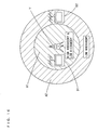
- Fig. 16 is a diagram showing the relationship between a place where a digital broadcasting receiver is installed and a receiving area of a broadcasting signal.
- a first digital broadcasting receiver D1 is installed in a first area A1 within a predetermined distance from a television tower T
- a second digital broadcasting receiver D2 is installed in a second area A2 outside the first area A1.
- Broadcasting signals in a low hierarchy and a high hierarchy are transmitted from the television tower T using two different modulation systems.
- the broadcasting signal in the high hierarchy and the broadcasting signal in the low hierarchy can be received in the first area A1, while only the broadcasting signal in the low hierarchy can be received in the second area A2.
- each of broadcasting stations transmits service list data with the service list data multiplexed on a broadcasting signal in a low hierarchy. This allows a digital broadcasting receiver installed in a place where a receiving environment is bad to also stably acquire the service list data.
- ID numbers for specifying all services that are broadcast by each of the broadcasting stations and the types thereof are listed in the service list data. Even in a digital broadcasting receiver that cannot receive the broadcasting signal in the high hierarchy, therefore, the service broadcast in the high hierarchy is incorporated into a channel list. When an electronic program guide (EPG) is displayed on a screen of the digital broadcasting receiver, for example, therefore, it is displayed with programs that cannot be viewed incorporated therein.
- EPG electronic program guide
- An object of the present invention is to provide a digital broadcasting receiver that can perform a comfortable tuning operation.
- the receiving state determiner can determine for each of the receivable services whether the service is being broadcast or the broadcasting thereof is stopped. Therefore, the separator can reliably separate the service whose broadcasting is stopped as a receivable service, and can therefore more reliably separate the receivable service.
- the separator separates receivable services out of services in list information. Even if the list information is transmitted with the list information multiplexed on a broadcasting signal in a low hierarchy, therefore, it is possible to prevent the digital broadcasting receiver from erroneously recognizing that the unreceivable service out of the services in the list information is receivable.
- the selector can select only the service separated by the separator. Therefore, the unreceivable service is not selected. This allows a time period required to select the service to be shortened.
- a frequency band of 6 MHz is assigned to each of broadcasting stations in Japan.
- Each of the broadcasting stations does a broadcast using 13 of 14 blocks obtained by equally dividing the assigned frequency band of 6 MHz and uses the remaining one block to prevent interference with a broadcasting signal in an adjacent frequency band.
- Each of the above-mentioned 13 blocks used for the broadcast is hereinafter referred to as a segment.
- Each of the frequency bands respectively assigned to the broadcasting stations is referred to as a physical channel.
- each of the broadcasting stations can classify the above-mentioned 13 segments into a plurality of hierarchies that differ in modulation systems.
- the modulation systems include a 64 QAM (Quadrature Amplitude Modulation) system for generating a broadcasting signal in a high hierarchy having a large amount of transmittable data and a QPSK (Quadrature Phase Shift Keying) system for generating a broadcasting signal in a low hierarchy having a small amount of transmittable data.
- QAM Quadrature Amplitude Modulation
- QPSK Quadrature Phase Shift Keying
- Each of the broadcasting stations shall transmit service list data with the service list data multiplexed on the broadcasting signal in the low hierarchy.
- the service list data is generated for each of the physical channels.
- the service list data include an ID (identification) number for specifying a service broadcast on each of the physical channels and the name of the service (e.g., a television broadcast, a radio broadcast, and a data broadcast). The details of the service list data will be described later.
- each of the broadcasting stations can multiplex a plurality of services on one broadcasting signal. Therefore, the plurality of services can be provided by one of the physical channels.
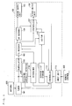
- Fig. 1 is a block diagram showing the configuration of a television receiver according to a first embodiment of the present invention.
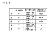
- Fig. 2 is a schematic view showing an example of service list data transmitted from each of broadcasting stations.
- Fig. 2 shows service list data from a broadcasting station (physical channel) that broadcasts five services.
- a television receiver 100 includes a tuner 101, a demodulator 102, a TS (Transport Stream) decoder 103, an AV (Audio Visual) decoder 104, a sound output unit 105, an editor 106, a synthesizer 107, a video output unit 108, a receiving intensity detector 109, a determiner 110, a service list storage 111, and a controller 112.
- a tuner 101 includes a tuner 101, a demodulator 102, a TS (Transport Stream) decoder 103, an AV (Audio Visual) decoder 104, a sound output unit 105, an editor 106, a synthesizer 107, a video output unit 108, a receiving intensity detector 109, a determiner 110, a service list storage 111, and a controller 112.
- service list data includes an ID number for specifying each of services, the name of the service, and hierarchical information.
- the hierarchical information represents a hierarchy in which the service is broadcast.
- a plurality of digital broadcasting signals (hereinafter abbreviated as broadcasting signals) is inputted to the tuner 101 from an antenna 901.
- the tuner 101 tunes in to one physical channel in accordance with a tuning signal outputted from the control unit 112, described later, and outputs a broadcasting signal of the physical channel to the demodulator 102.
- the demodulator 102 demodulates the broadcasting signal outputted from the tuner 101, and generates a transport stream conforming to an MPEG (Moving Picture Experts Group)-2 Standard. Furthermore, the demodulator 102 error-corrects the generated transport stream, and outputs the error-corrected transport stream to the TS decoder 103.
- MPEG Motion Picture Experts Group
- a tuner 101 and one demodulator 102 are illustrated in Fig. 1 , a tuner 101 and a demodulator 102 corresponding to a broadcasting signal in a high hierarchy and a tuner 101 and a demodulator 102 corresponding to a broadcasting signal in a low hierarchy are actually provided because each of the broadcasting stations does a broadcast using two modulation systems in this example.
- the TS decoder 103 separates a sound stream, a video stream, electric program guide (EPG) data, data broadcast-related data, service list data (see Fig. 2 ), and so on from the transport stream outputted from the demodulator 102.
- EPG electric program guide
- the TS decoder 103 outputs the separated electronic program guide data to the editor 106, outputs the separated data broadcast-related data to the synthesizer 107, and outputs the separated service list data to the determiner 110. Furthermore, the TS decoder 103 outputs from the separated sound stream and video stream a sound stream and a video stream corresponding to a service designated by a designation signal outputted from the controller 112, described later, to the AV decoder 104.
- the AV decoder 104 ( Fig. 1 ) decodes the sound stream and the video stream that are outputted from the TS decoder 103, to generate sound data and video data. Furthermore, the AV decoder 104 outputs the generated sound data to the sound output unit 105, and outputs the generated video data to the synthesizer 107.
- the sound output unit 105 includes a sound output device such as a speaker, and outputs the sound data outputted from the AV decoder 104 as a sound.
- the editor 106 edits the electronic program guide data outputted from the TS decoder 103 on the basis of an ID number stored in the service list storage 111, described later, and outputs the edited electronic program guide data to the synthesizer 107. Specifically, the editor 106 generates the electronic program guide data including only a service corresponding to the ID number stored in the service list storage 111.
- the synthesizer 107 synthesizes, when a synthetic signal, described later, is outputted from the controller 112, the video data outputted from the AV decoder 104 and data designated by the synthetic signal (the data broadcast-related data outputted from the TS decoder 103 or the electronic program guide data outputted from the editor 106), and outputs the synthesized data (hereinafter referred to as synthetic data) to the video output unit 108. Furthermore, the synthesizer 107 outputs the video data outputted from the AV decoder 104 as it is to the video output unit 108 when the synthetic signal is not outputted from the controller 112.
- the video output unit 108 includes a display device such as a liquid crystal display panel or a plasma display panel, and displays the synthetic data or the video data outputted from the synthesizer 107 as a video. Note that when the synthetic data is displayed as a video, an electronic program guide or the like is presented by OSD (On Screen Display) on the display device.
- OSD On Screen Display
- the receiving intensity detector 109 determines whether or not the broadcasting signal of the physical channel that is being tuned in to by the tuner 101 is being received. Specifically, the receiving intensity detector 109 determines that the broadcasting signal that is being tuned in to by the tuner 101 is being received when it detects the broadcasting signal outputted from the tuner 101, while determining that the broadcasting signal that is being tuned in to by the tuner 101 is not being received when it cannot detect the broadcasting signal outputted from the tuner 101.
- the receiving intensity detector 109 outputs, when it determines that the broadcasting signal of the physical channel that is being tuned in to by the tuner 101 is not being received, a first notification signal for notifying the controller 112 of the results of the determination. Furthermore, the receiving intensity detector 109 detects, when it determines that the broadcasting signal of the physical channel that is being tuned in to by the tuner 101 is being received, the receiving intensity of the broadcasting signal. Note that the receiving intensity can be detected by measuring the level of the broadcasting signal, for example.
- the determiner 110 determines whether or not each of the services in the service list data outputted from the TS decoder 103 is receivable on the basis of the detected receiving intensity. The details will be described later.
- the determiner 110 outputs, when it has determined whether or not all the services in the service list data outputted from the TS decoder 103 are receivable, a second notification signal for notifying the controller 112 of the results of the determination.
- the service list storage 111 stores an ID number (see Fig. 2 ) for specifying the service that has been determined to be receivable by the determiner 110.
- the controller 112 includes a storage, and stores the order of physical channels to be scanned when a channel scan is performed. The details of the channel scan will be described later.
- the controller 112 generates a tuning signal on the basis of the above-mentioned order stored in the storage or an operation signal outputted from an input unit 113, described later, and outputs the tuning signal to the tuner 101.
- the controller 112 when the television receiver 100 performs a channel scan, the controller 112 outputs a tuning signal for designating each of the physical channels in accordance with the above-mentioned order stored in the storage. Note that the controller 112 outputs, when the above-mentioned first or second notification signal is outputted from the receiving intensity detector 109 or the determiner 110, a tuning signal for designating the physical channel different from the physical channel that is being tuned in to. The details will be described later.
- the controller 112 when the viewer operates a remote control 902 or an operation button of the input unit 113, described later, to select a desired service, the controller 112 outputs a tuning signal for designating the physical channel on which the selected service is broadcast on the basis of the operation signal. Note that the viewer can select the desired service by referring to the electronic program guide displayed on the display device, for example.
- the controller 112 generates a designation signal for designating the service selected by the viewer on the basis of the operation signal, and outputs the designation signal to the TS decoder 103. Note that the controller 112 generates the designation signal only for the service specified by the ID number stored in the service list storage 111. When the viewer performs an up-and-down operation with the remote control 902, for example, only the services corresponding to the stored ID numbers are selected in order.
- the controller 112 generates a synthetic signal on the basis of the above-mentioned operation signal.
- the controller 112 outputs a synthetic signal for designating the data broadcast-related data to the synthesizer 107.
- the data broadcast-related data is presented by OSD on the display device.
- the controller 112 When the viewer attempts to display the electronic program guide by operating the remote control 902, for example, the controller 112 outputs a synthetic signal for designating the electronic program guide data to the synthesizer 107.
- the electronic program guide is presented by OSD on the display device.
- the input unit 113 includes a remote control signal receiver and an operation button, and generates an operation signal on the basis of a remote control signal transmitted from the remote control 902 or the depression of the operation button, and outputs the operation signal to the controller 112.
- the editor 106, the synthesizer 107, the receiving intensity detector 109, the determiner 110, and the controller 112 may be realized by a microcomputer and its control program, or any one or all of them may be realized by hardware such as an electronic circuit.
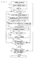
- Fig. 3 is a flow chart showing a channel scan operation of the television receiver 100 ( Fig. 1 ).
- the controller 112 ( Fig. 1 ) first generates a tuning signal for designating a first physical channel on the basis of the order stored in the storage, and outputs the generated tuning signal to the tuner 101 ( Fig. 1 ).
- the tuner 101 tunes in to the physical channel in accordance with the tuning signal (step S2).
- the receiving intensity detector 109 determines whether or not the tuner 101 is receiving a broadcasting signal of the physical channel tuned in to (step S3).
- the receiving intensity detector 109 detects a receiving intensity (step S4).
- the receiving intensity detector 109 determines a receivable hierarchy on the basis of the detected receiving intensity. Specifically, the receiving intensity detector 109 determines that broadcasting signals in both a low hierarchy and a high hierarchy are receivable when the receiving intensity is not less than a predetermined threshold value on the physical channel that is being tuned in to, while determining that only the broadcasting signal in the low hierarchy is receivable when the receiving intensity is less than the predetermined threshold value.
- the determiner 110 acquires service list data from the TS decoder 103 ( Fig. 1 ) (step S6).
- the determiner 110 selects one of services in the acquired service list data (step S7).
- the determiner 110 determines a hierarchy in which the service selected in the step S7 is broadcast on the basis of hierarchical information (see Fig. 2 ) in the service list data acquired in the step S6 (step S8).
- the determiner 110 compares the receivable hierarchy determined in the step S5 with the hierarchy determined in the step S8, and determines whether or not the service selected in the step S7 is receivable (step S9).
- the determiner 110 determines that the selected service is receivable.
- the determiner 110 determines that the selected service is unreceivable.
- the determiner 110 stores an ID number for specifying the service in the service list storage 111 ( Fig. 1 ) (step S10).
- the determiner 110 determines whether or not the processes in the foregoing step S7 to S10 are terminated for all services (five services in Fig. 2 ) in the service list data acquired in the step S6 (step S11).
- the controller 112 determines whether or not the processes in the steps S1 to S11 are terminated for all physical channels stored in the storage (step S12).
- step S12 When it is determined in the step S12 that the processes in the steps S1 to S11 are terminated for all the physical channels, the channel scan operation is terminated.
- step S3 When it is determined in the step S3 that the broadcasting signal is not being received, the controller 112 proceeds to the step S12.
- the determiner 110 proceeds to the step S11.
- the determiner 110 returns to the step S7, to select one of the services that have not been determined to be receivable or unreceivable.
- the controller 112 When it is determined in the step S12 that the processes in the steps S1 to S12 are not terminated for all the physical channels, that is, when any one of the physical channels has not been scanned, the controller 112 returns to the step S1, to generate a tuning signal for designating the subsequent physical channel in accordance with the order stored in the storage and output the generated tuning signal to the tuner 101.
- all ID numbers in the service list data are stored in the service list storage 111.
- "101", “102”, “301”, “701", and “901" are stored as ID numbers in the service list storage 111.
- the television receiver 100 can receive only the broadcasting signal in the low hierarchy, for example, only the ID number for specifying the service assigned hierarchical information representing the low hierarchy is stored in the service list storage 111.
- ID numbers for specifying the service assigned hierarchical information representing the low hierarchy.
- the receiving intensity of the physical channel that is being tuned in to is detected when the channel scan is performed. Furthermore, the receivable hierarchy on the physical channel that is being tuned in to is determined on the basis of the detected receiving intensity. It is determined for each of the services whether or not the service is receivable by comparing the results of the determination with the hierarchical information in the service list data, and the ID number for specifying the service that has been determined to be receivable is stored in the service list storage 111.
- the viewer can select only the service corresponding to the ID number stored in the service list storage 111.
- the unreceivable service is not selected. This allows a time period required to select the service to be shortened.
- the television receiver 100 When the television receiver 100 is so set that the service can be selected by inputting the ID number with the remote control 902 or the input unit 113, for example, it is possible to immediately indicate, when the viewer inputs the ID number for specifying the unreceivable service, that the service is unreceivable using the display device. This allows the viewer to easily and immediately recognize the unreceivable service.
- the electronic program guide data can be edited on the basis of the ID numbers stored in the service list storage 111.
- the viewer displays the electronic program guide on the display device, therefore, it is possible to prevent the unreceivable service from being incorporated into the electronic program guide. This can prevent the viewer from selecting the unreceivable service. Furthermore, only the receivable service is incorporated into the electronic program guide. Therefore, the viewer can easily find out the desired service.
- the viewer can perform a comfortable tuning operation.
- each of the broadcasting stations can transmit the service list data with the service list data multiplexed on the broadcasting signal in the low hierarchy. Therefore, the television receiver 100 can be caused to reliably receive the service list data.
- a television receiver according to a second embodiment differs from the television receiver 100 ( Fig. 1 ) according to the first embodiment in the following points.
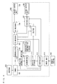
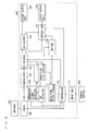
- Fig. 4 is a block diagram showing the configuration of the television receiver according to the second embodiment.
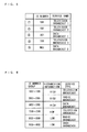
- Fig. 5 is a schematic view showing an example of service list data transmitted from each of broadcasting stations. Note that the service list data does not include hierarchical information in the present embodiment, as shown in Fig. 5 .
- a television receiver 200 includes a hierarchical information storage 114.
- the hierarchical information storage 114 stores information representing the relationship between an ID number and a hierarchy (hereinafter referred to as by-ID hierarchical information). Note that the relationship between an ID number and a hierarchy is previously determined by a broadcasting standard.
- Fig. 6 shows an example of the by-ID hierarchical information. Note that a predetermined number of (100 in this example) ID numbers are assigned for each combination of a hierarchy and a service type in the example of Fig. 6 . For example, an ID number assigned to a television broadcast in a high hierarchy is set to any one of ID numbers in an ID number group "100 to 199", and an ID number assigned to a television broadcast in a low hierarchy is set to any one of ID numbers in an ID number group "700 to 799".
- Fig. 7 is a flow chart showing a channel scan operation of the television receiver 200 ( Fig. 4 ).
- the flow chart shown in Fig. 7 differs from the flow chart shown in Fig. 3 in the following points.
- a determiner 110 acquires service list data in the step S6, and then acquires by-ID hierarchical information from the hierarchical information storage 114 ( Fig. 4 ) (step S61).
- the determiner 110 selects one of services in the service list data acquired in the step S6 (step S7).
- the determiner 110 determines a hierarchy in which the service selected in the step S7 is broadcast on the basis of the by-ID hierarchical information acquired in the step S61 (step S8).
- the determiner 110 determines that a hierarchy in which the data broadcast 1 is broadcast is a high hierarchy.
- the determiner 110 compares a receivable hierarchy determined in the step S5 with the hierarchy determined in the step S81, and determines whether or not the service selected in the step S7 is receivable (step S91).
- the determiner 110 proceeds to the step S10 when it determines in the step S91 that the service is receivable, while proceeding to the step S11 when it determines in the step S91 that the service is unreceivable. Note that other processes are the same as those shown in Fig. 4 .
- all ID numbers in the service list data are stored in a service list storage 111.
- the television receiver 200 can receive only the broadcasting signal in the low hierarchy, for example, only the ID number belonging to the ID number group ( Fig. 6 ) in the low hierarchy out of the ID numbers in the service list data (see Fig. 5 ) is stored in the service list storage 111.
- the service list storage 111 In the examples of Figs. 5 and 6 , "701" and "901" are stored as ID numbers in the service list storage 111.
- the receiving intensity of the physical channel that is being tuned in to is detected when the channel scan is performed. Furthermore, the receivable hierarchy on the physical channel that is being tuned in to is determined on the basis of the detected receiving intensity. It is determined for each of the services whether or not the service is receivable by comparing the results of the determination with the by-ID hierarchical information stored in the hierarchical information storage 114, and the ID number for specifying the service that has been determined to be receivable is stored in the service list storage 111.
- the viewer can select only the service corresponding to the ID number stored in the service list storage 111. This allows a time period required to select the service to be shortened.
- the electronic program guide data can be edited on the basis of the ID numbers stored in the service list storage 111. This can prevent the unreceivable service from being incorporated into the electronic program guide.
- the viewer can perform a comfortable tuning operation.
- each of the broadcasting stations can transmit the service list data with the service list data multiplexed on the broadcasting signal in the low hierarchy. Therefore, the television receiver 200 can be caused to reliably receive the service list data.
- the hierarchy in which each of the service is broadcast can be recognized on the basis of the by-ID hierarchical information. Therefore, each of the broadcasting stations need not provide hierarchical information to the service list data. This allows the other information to be multiplexed on the broadcasting signal, thereby making it feasible to diversify broadcasting.
- a television receiver according to a third embodiment differs from the television receiver 100 ( Fig. 1 ) according to the first embodiment in the following points.
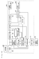
- Fig. 8 is a block diagram showing the configuration of the television receiver according to the third embodiment. Note that the service list data shown in Fig. 5 shall be transmitted from each of broadcasting stations in the present embodiment.
- a television receiver 300 includes a broadcasting signal detector 115, a receiving list creator 116, a receiving state storage 117, and a PMT detector 118. Note that the receiving intensity detector 109, the determiner 110, and the service list storage 111 shown in Fig. 1 are not included in the television receiver 300 according to the present embodiment.
- a TS decoder 103 separates a sound stream, a video stream, electric program guide data, data broadcast-related data, service list data, and a PMT (Program Map Table) from a transport stream outputted from a demodulator 102.
- the TS decoder 103 outputs the separated service list data to the receiving list creator 116, and outputs the separated PMT to the PMT detector 118.
- the PMT is a table representing constituent elements (a video stream, a sound stream, a data stream, etc.) in each of services, and is transmitted in the same hierarchy as constituent elements in the corresponding service.
- the broadcasting signal detector 115 determines whether or not a broadcasting signal of a physical channel that is being tuned in to by a tuner 101 is being received, similarly to the receiving intensity detector 109 shown in Fig. 1 . Furthermore, the broadcasting signal detector 115 outputs, when it determines that the tuner 101 is not receiving the broadcasting signal of the physical channel that is being tuned in to by the tuner 101, a third notification signal for notifying a controller 112 of the results of the determination.
- the receiving list creator 116 creates a receiving list on the basis of the service list data outputted from the TS decoder 103.
- Fig. 9 shows an example of a receiving list in an initial state. Note that the example of Fig. 9 shows a receiving list created on the basis of the service list data shown in Fig. 5 .
- the receiving list represents the relationship between an ID number for specifying each of services and the receiving state of the service.
- the receiving list creator 116 creates a receiving list, considering that the receiving states of all the services are unreceivable states (states displayed as "bad" in Fig. 9 ) in the initial state.
- the receiving state storage 117 stores the receiving list created by the receiving list creator 116.
- the PMT detector 118 detects the PMT outputted from the TS decoder 103 while determining the receiving state of each of the services on the basis of the detected PMT. Specifically, the PMT detector 118 determines, when it detects the PMT, that the service corresponding to the PMT is receivable, and changes the receiving state in the receiving list stored in the receiving state storage 117.
- Fig. 10 is an example of a receiving list in which the receiving state of each of services has been changed.
- the PMT detector 118 changes, when it determines that a television broadcast 1 (ID number : 101) shown in Fig. 5 is receivable, for example, the receiving state of a service assigned the ID number 101 to a receivable state (a state displayed as "good” in Fig. 10 ) on the receiving list, as shown in Fig. 10 .
- the PMT detector 118 outputs, when the receiving state has been determined for all the services in the receiving list, a fourth notification signal for notifying the controller 112 of the results of the determination.
- the controller 112 outputs, when the above-mentioned third or fourth notification signal is outputted from the broadcasting signal detector 115 or the PMT detector 118, a tuning signal for designating a physical channel different from a physical channel that is being tuned in to the tuner 101.
- an editor 106 edits the electronic program guide data outputted from the TS decoder 103 on the basis of the ID number for specifying the service that is made receivable in the receiving list stored in the receiving list creator 117, and outputs the edited electronic program guide data to a synthesizer 107. Specifically, the editor 106 creates the electronic program guide data including only the service that has been determined to be receivable.
- controller 112 generates a designation signal only for the service that is made receivable in the receiving list.
- broadcasting signal detector 115 the receiving list creator 116, and the PMT detector 118 may be realized by a microcomputer and its control program. Alternatively, any one or all of them may be realized by hardware such as an electronic circuit.
- Fig. 11 is a flow chart showing a channel scan operation of the television receiver 300 ( Fig. 8 ).
- the flow chart shown in Fig. 11 differs from the flow chart shown in Fig. 3 in the following points.
- the broadcasting signal detector 115 determines whether or not the tuner 101 is receiving a broadcasting signal of the physical channel tuned in to (step S31).
- the receiving list creator 116 acquires, when it is determined that the broadcasting signal is being received, service list data from the TS decoder 103 ( Fig. 8 ) (step S62).
- the receiving list creator 116 creates a receiving list on the basis of the acquired service list data, and stores the created receiving list in the receiving state storage 117 ( Fig. 8 ) (step S63).
- the PMT detector 118 selects one service (ID number) from the receiving list stored in the receiving state storage 117 (step S71).
- the PMT detector 118 determines whether or not a PMT corresponding to the selected service (ID number) is detected (step S92).
- the PMT detector 118 changes the receiving state of the service selected in the step S71 to a receivable state in the receiving list stored in the receiving list storage 117 (step S101).
- the PMT detector 118 determines whether or not the processes in the foregoing step S71 to S101 are terminated for all the services in the receiving list created in the step S63 (step S111).
- the controller 112 determines whether or not the processes in the steps S1 to S111 are terminated for all physical channels stored in the storage (step S121).
- the controller 112 proceeds to the step S121.
- the PMT detector 118 proceeds to the step S111 without changing the receiving state in the receiving list.
- the PMT detector 118 When it is determined in the step S111 that the processes are not terminated for all the services, i.e., when any of the services have not been determined to be receivable or unreceivable, the PMT detector 118 returns to the step S71, to select one of the services that have not been determined.
- the controller 112 When it is determined in the step S121 that the processes in the steps S1 to S111 are not terminated for all the physical channels, that is, when any one of the physical channels has not been scanned, the controller 112 returns to the step S1, to generate a tuning signal for designating the subsequent physical channel in accordance with the order stored in the storage and output the generated tuning signal to the tuner 101.
- the television receiver 300 it is determined that only the service corresponding to the received PMT is receivable when the channel scan is performed.
- the television receiver 300 cannot receive only the broadcasting signal in the high hierarchy, therefore, it is possible to prevent the service broadcast in the high hierarchy from being determined to be receivable.
- the viewer can select only the service that has been determined to be receivable. This allows a time period required to select the service to be shortened.
- the electronic program guide data can be created on the basis of the ID number for specifying the service that has been determined to be receivable. This can prevent the unreceivable service from being incorporated into the electronic program guide.
- the viewer can perform a comfortable tuning operation.
- each of the broadcasting stations can transmit the service list data with the service list data multiplexed on the broadcasting signal in the low hierarchy. Therefore, the television receiver 300 can be caused to reliably receive the service list data.
- the television receiver 300 can specify the receivable service without determining the receivable hierarchy. Therefore, the necessity of measuring the receiving intensity of the broadcasting signal is eliminated, thereby allowing the constituent elements in the television receiver 300 to be simplified. This allows the manufacturing processes and the manufacturing cost of the television receiver 300 to be reduced.
- a television receiver according to a fourth embodiment differs from the television receiver 300 ( Fig. 8 ) according to the third embodiment in the following points.
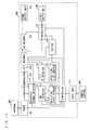
- Fig. 12 is a block diagram showing the configuration of the television receiver according to the fourth embodiment.
- a television receiver 400 As shown in Fig. 12 , a television receiver 400 according to the present embodiment has an EIT detector 119 provided in place of the PMT detector 118 shown in Fig. 8 .
- a TS decoder 103 separates a sound stream, a video stream, electric program guide data, data broadcast-related data, service list data, and an EIT (Event Information Table) from a transport stream outputted from a demodulator 102.
- the TS decoder 103 outputs the separated service list data to a receiving list creator 116, and outputs the separated EIT to the EIT detector 119.
- the EIT is a table representing program information relating to each of services, and is transmitted in the same hierarchy as constituent elements (a video stream, a sound stream, a data stream, etc.) in the corresponding service.
- the EIT detector 119 detects the EIT outputted from the TS decoder 103 while determining the receiving state of each of the services on the basis of the detected EIT. More specifically, the EIT detector 119 detects, when it detects the EIT, that the service corresponding to the EIT is receivable, and changes the receiving state in a receiving list stored in a receiving state storage 117, similarly to the PMT detector 118 shown in Fig. 8 .
- the EIT detector 119 outputs, when the receiving state has been determined for all the services in the receiving list, a fifth notification signal for notifying a controller 112 of the results of the determination.
- the controller 112 outputs, when the above-mentioned third or fifth notification signal is outputted from a broadcasting signal detector 115 or the EIT detector 119, a tuning signal for designating a physical channel different from a physical channel that is being tuned in to to a tuner 101.
- the EIT detector 119 may be realized by a microcomputer and its control program or may be realized by hardware such as an electronic circuit.
- Fig. 13 is a flow chart showing a channel scan operation of the television receiver 400 ( Fig. 12 ).
- the flow chart shown in Fig. 13 differs from the flow chart shown in Fig. 11 in the following points.
- the receiving list creator 116 creates a receiving list in the step S63
- the created receiving list ( Fig. 9 ) is stored in the receiving state storage 117 ( Fig. 12 ), and the EIT detector 119 ( Fig. 12 ) then selects one of services (ID numbers) in the stored receiving list (step S72).
- the EIT detector 119 determines whether or not an EIT corresponding to the selected service (ID number) is detected (step S93).
- the EIT detector 119 changes the receiving state of the service selected in the step S72 to a receivable state in the receiving list stored in the receiving list storage 117 (step S102).
- the EIT detector 119 determines whether or not the processes in the foregoing step S72 to S102 are terminated for all the services in the receiving list created in the step S63 (step S112).
- the controller 112 ( Fig. 12 ) proceeds to the step S121.
- the EIT detector 119 proceeds to the step S112 without changing the receiving state in the receiving list.
- the EIT detector 119 When it is determined in the step S112 that the processes are not terminated for all the services, i.e., when any of the services have not been determined to be receivable or unreceivable, the EIT detector 119 returns to the step S72, to select one of the services that have not been determined.
- the television receiver 400 it is determined that only the service corresponding to the received EIT is receivable when the channel scan is performed.
- the television receiver 400 cannot receive a broadcasting signal in a high hierarchy, therefore, it is possible to prevent the service broadcast in the high hierarchy from being determined to be receivable.
- the viewer can select only the service that has been determined to be receivable. This allows a time period required to select the service to be shortened.
- the electronic program guide data can be created on the basis of the ID number for specifying the service that has been determined to be receivable. This can prevent the unreceivable service from being incorporated into an electronic program guide.
- the viewer can perform a comfortable tuning operation.
- each of the broadcasting stations can transmit the service list data with the service list data multiplexed on a broadcasting signal in a low hierarchy. Therefore, the television receiver 400 can be caused to reliably receive the service list data.
- the television receiver 400 can specify a receivable service without determining a receivable hierarchy. Therefore, the necessity of measuring the receiving intensity of the broadcasting signal is eliminated, thereby allowing the constituent elements in the television receiver 400 to be simplified. This allows the manufacturing processes and the manufacturing cost of the television receiver 400 to be reduced.
- the EIT is also transmitted when the broadcasting of the corresponding service is stopped.
- the television receiver 400 can determine that the service whose broadcasting is temporarily stopped is also receivable. This can prevent the television receiver 400 from determining the service that is made receivable by resuming the broadcasting to be unreceivable. As a result, it is possible to more reliably determine the receivable service.
- a television receiver according to a fifth embodiment differs from the television receivers 300 and 400 ( Figs. 8 and 12 ) according to the third and fourth embodiments in the following points.
- Fig. 14 is a block diagram showing the configuration of the television receiver according to the fifth embodiment.
- a television receiver 500 As shown in Fig. 14 , a television receiver 500 according to the present embodiment is provided with both a PMT detector 118 shown in Fig. 8 and an EIT detector 119 shown in Fig. 12 .
- a TS decoder 103 separates a sound stream, a video stream, electric program guide data, data broadcast-related data, service list data, a PMT, and an EIT from a transport stream outputted from a demodulator 102. Furthermore, the TS decoder 103 outputs the separated service list data to a receiving list creator 116, outputs the separated PMT to the PMT detector 118, and outputs the separated EIT to the EIT detector 119.
- Fig. 15 is a schematic view showing an example of a receiving list in an initial state created by a receiving list creator 116 in the present embodiment.
- the receiving list includes an ID number for specifying each of services and the receiving states of the EIT and the PMT corresponding to the service in the present embodiment. Note that the receiving list creator 116 creates the receiving list, considering that neither the EIT nor the PMT is received in the initial state.
- the PMT detector 118 changes, when it detects the PMT outputted from the TS decoder 103, a corresponding PMT receiving state in a receiving list stored in a receiving state storage 117 into a receivable state.
- the EIT detector 119 changes, when it detects the EIT outputted from the TS decoder 103, a corresponding EIT receiving state in the receiving list stored in the receiving state storage 117 into a receivable state.
- the PMT detector 118 and the EIT detector 119 determine the receiving state by the same operation as the operation described in the flow charts shown in Figs. 10 and 13 .
- the PMT is not transmitted when the broadcasting of the corresponding service is stopped.
- the EIT is also transmitted when the broadcasting of the corresponding service is stopped.
- a controller 112 and an editor 106 determine the service in which the EIT is received to be receivable, determine the service in which not the PMT but the EIT is received as a service whose broadcasting is stopped, and determine the service in which neither the EIT nor the PMT is received to be unreceivable.
- the present embodiment it can be determined whether the service that is not currently received is unreceivable or is receivable, though the broadcasting thereof is stopped. This can prevent the service whose broadcasting is stopped from being determined to be unreceivable.
- the editor 106 can indicate, for the service whose broadcasting is stopped, that broadcasting is stopped in an electronic program guide because it edits the electronic program guide data on the basis of the receiving list stored in the receiving state storage 117. This allows a viewer to more accurately recognize the receivable service.
- controller 112 can be so set that a designation signal is generated only for the service that has been determined to be being broadcast, for example. In this case, the viewer can select only the service that is being broadcast. This allows a time period required to select the service to be shortened.
- the viewer selects the service whose broadcasting is stopped, for example, it can be indicated on a display device that the broadcasting of the service is stopped. This allows the viewer to more accurately recognize the receiving state of the service.
- the digital broadcasting receiver may be a mobile receiver such as a cellular phone, a car television, a car navigation system, or a PDA (Personal Digital Assistant).
- the digital broadcasting receiver 10 may be a personal computer or the like including a DVD (Digital Versatile Disc) reproducing apparatus, a DVD recording/reproducing apparatus, a hard disk recording/reproducing apparatus, a set top box (STB), or a digital tuner.
- the sound output unit 105 has not a sound output device but a sound output terminal
- the video output unit 108 has not a video display device but a video output terminal.
- the sound output terminal and the video output terminal are connected to a sound input terminal and a video input terminal of the television receiver.
- the sound output terminal and the video output terminal are respectively connected to a sound input terminal and a video input terminal of a display panel.
- the receiving intensity detector 109 and the broadcasting signal detector 115 detect the broadcasting signal outputted from the tuner 101, to determine whether or not the tuner 101 is receiving the broadcasting signal, they may determine on the basis of the level of the broadcasting signal outputted from the tuner 101 whether or not the tuner 101 is receiving the broadcasting signal.
- the tuner 101 may determine that the tuner 101 is receiving the broadcasting signal when the level of the broadcasting signal outputted from the tuner 101 is not less than a predetermined threshold value, while determining that the tuner 101 is not receiving the broadcasting signal when the level of the broadcasting signal outputted from the tuner 101 is less than the predetermined threshold value.
- a limit value at which the broadcasting signal in the low hierarchy is receivable can be used as the threshold value.
- the receiving intensity is detected by the level of the broadcasting signal
- the receiving intensity may be detected on the basis of a C/N (Carrier to Noise ratio) or may be detected on the basis of an error rate at the time of demodulation in the demodulator 102 or the AV decoder 104.
- C/N Carrier to Noise ratio
- the tuner 101 is an example of a receiver
- the demodulator 102 is an example of a demodulator
- the service list data is an example of list information of services
- the TS decoder 103 is an example of an extractor
- the receiving intensity detector 109 is an example of a hierarchy determiner
- the determiner 110 is an example of a hierarchy determiner
- the determiner 110 is an example of a PMT detector 118, or the EIT detector 119 is an example of a separator
- the controller 112 is an example of a selector
- the hierarchical information is an example of information relating to a hierarchy in which a service is broadcast
- the ID number is an example of information for specifying a service
- the by-ID hierarchical information is an example of the relationship between information for specifying a service and a hierarchy
- the hierarchical information storage 114 is an example of a storage
- the determiner 110 is an example of a determiner
- the control 112 is an example of a receiving state determiner
- the present invention is applicable to various types of digital broadcasting receiving apparatuses having general digital broadcasting receiving functions such as a television receiver, a personal computer, a DVD decoder, and a cellular phone.
- a television receiver includes a TS decoder, an editor, a receiving intensity detector, a determiner, and a service list storage.
- the TS decoder separates electronic program guide data, service list data, and so on from a transport stream.
- the receiving intensity detector detects the receiving intensity of a physical channel that is being tuned in to, and determines a receivable hierarchy.
- the determiner determines whether or not each of services in a service list is receivable on the basis of the results of the determination by the receiving intensity detector, and stores an ID number for specifying the service that has been determined to be receivable in the service list storage.
- the editor generates electronic program guide data including only the receivable service on the basis of the electronic program guide data separated by the TS decoder and the ID number stored in the service list storage.
Landscapes
- Engineering & Computer Science (AREA)
- Signal Processing (AREA)
- Multimedia (AREA)
- Databases & Information Systems (AREA)
- Human Computer Interaction (AREA)
- Circuits Of Receivers In General (AREA)
- Television Systems (AREA)
- Two-Way Televisions, Distribution Of Moving Picture Or The Like (AREA)
Applications Claiming Priority (2)
| Application Number | Priority Date | Filing Date | Title |
|---|---|---|---|
| JP2006155717A JP2007325153A (ja) | 2006-06-05 | 2006-06-05 | デジタル放送受信機 |
| PCT/JP2007/057771 WO2007141954A1 (ja) | 2006-06-05 | 2007-04-06 | デジタル放送受信機 |
Publications (2)
| Publication Number | Publication Date |
|---|---|
| EP2034732A1 true EP2034732A1 (de) | 2009-03-11 |
| EP2034732A4 EP2034732A4 (de) | 2012-12-05 |
Family
ID=38801219
Family Applications (1)
| Application Number | Title | Priority Date | Filing Date |
|---|---|---|---|
| EP07741207A Withdrawn EP2034732A4 (de) | 2006-06-05 | 2007-04-06 | Digitalausstrahlungsempfänger |
Country Status (5)
| Country | Link |
|---|---|
| US (1) | US20090262250A1 (de) |
| EP (1) | EP2034732A4 (de) |
| JP (1) | JP2007325153A (de) |
| CN (1) | CN101461157B (de) |
| WO (1) | WO2007141954A1 (de) |
Cited By (1)
| Publication number | Priority date | Publication date | Assignee | Title |
|---|---|---|---|---|
| EP3672268A1 (de) * | 2018-12-22 | 2020-06-24 | Advanced Digital Broadcast S.A. | Zentralisierte inhaltsbezogene objektdatenbank in der middleware-schicht |
Families Citing this family (6)
| Publication number | Priority date | Publication date | Assignee | Title |
|---|---|---|---|---|
| KR101513557B1 (ko) * | 2008-02-04 | 2015-04-21 | 삼성전자주식회사 | 광대역 무선 접속 시스템의 매핑 테이블 생성 장치 및 방법 |
| JP4883130B2 (ja) * | 2009-04-16 | 2012-02-22 | パナソニック株式会社 | 移動型デジタル放送受信装置 |
| JP5676915B2 (ja) * | 2010-05-20 | 2015-02-25 | キヤノン株式会社 | 放送受信装置及びその制御方法 |
| JP6202864B2 (ja) * | 2013-04-09 | 2017-09-27 | 日本放送協会 | 送信装置 |
| US20170171604A1 (en) * | 2015-12-15 | 2017-06-15 | Le Holdings (Beijing) Co., Ltd. | Digital television device, soc decoder chip, and decoder |
| JP6238502B1 (ja) * | 2017-08-28 | 2017-11-29 | 日本放送協会 | 送信装置 |
Family Cites Families (28)
| Publication number | Priority date | Publication date | Assignee | Title |
|---|---|---|---|---|
| AU6675098A (en) * | 1997-02-28 | 1998-09-18 | Starsight Telecast Incorporated | Television control interface with electronic guide |
| US6359580B1 (en) * | 1997-03-18 | 2002-03-19 | Thomson Licensing S.A. | Multiple source keypad channel entry system and method |
| JP3526225B2 (ja) * | 1998-11-04 | 2004-05-10 | シャープ株式会社 | デジタル放送受信装置 |
| JP2001086494A (ja) * | 1999-09-10 | 2001-03-30 | Sharp Corp | デジタル放送受信機 |
| JP4534103B2 (ja) * | 2000-06-30 | 2010-09-01 | ソニー株式会社 | 受信機、テレビジョン受像機および受信方法 |
| JP2002101141A (ja) * | 2000-09-21 | 2002-04-05 | Hitachi Ltd | 受信装置 |
| JP2003087141A (ja) * | 2001-09-06 | 2003-03-20 | Victor Co Of Japan Ltd | デジタル放送受信機 |
| JP2003101812A (ja) * | 2001-09-26 | 2003-04-04 | Hitachi Ltd | 受信システムおよび携帯端末 |
| JP3920626B2 (ja) * | 2001-11-02 | 2007-05-30 | 三洋電機株式会社 | 再送信装置及びディジタル放送受信システム |
| KR20040072717A (ko) * | 2002-01-11 | 2004-08-18 | 코닌클리케 필립스 일렉트로닉스 엔.브이. | 전송 시스템 |
| US7886332B2 (en) * | 2002-03-19 | 2011-02-08 | Canon Kabushiki Kaisha | Television broadcast receiving apparatus |
| JP4145133B2 (ja) * | 2002-12-03 | 2008-09-03 | 三洋電機株式会社 | ディジタル放送受信装置 |
| ES2353872T3 (es) * | 2003-01-28 | 2011-03-07 | Thomson Licensing | Difusión espaciada en modo robusto. |
| JP2004282211A (ja) | 2003-03-13 | 2004-10-07 | Matsushita Electric Ind Co Ltd | 地上デジタルテレビジョン放送受信装置 |
| KR20040082035A (ko) * | 2003-03-17 | 2004-09-24 | 엘지전자 주식회사 | 모든 채널의 신호 세기 디스플레이 방법 |
| JP2004364216A (ja) * | 2003-06-09 | 2004-12-24 | Funai Electric Co Ltd | デジタル/アナログ放送受像機 |
| JP4007944B2 (ja) * | 2003-06-12 | 2007-11-14 | シャープ株式会社 | デジタル放送受信装置及び受信レベル表示方法 |
| JP2005117226A (ja) * | 2003-10-06 | 2005-04-28 | Alpine Electronics Inc | デジタル放送受信装置及びチャネル情報取得方法 |
| US7181170B2 (en) * | 2003-12-22 | 2007-02-20 | Motorola Inc. | Apparatus and method for adaptive broadcast transmission |
| KR20050075546A (ko) * | 2004-01-15 | 2005-07-21 | 삼성전자주식회사 | 프로그램 장르별로 분류된 채널맵을 이용하여 채널을전환하는 채널전환장치 및 그 방법 |
| JP4442238B2 (ja) * | 2004-02-04 | 2010-03-31 | ソニー株式会社 | 受信装置 |
| US8321907B2 (en) * | 2004-02-09 | 2012-11-27 | Panasonic Corporation | Broadcast receiving apparatus, broadcast receiving method, broadcast receiving program, and broadcast receiving circuit |
| JP4352976B2 (ja) * | 2004-04-20 | 2009-10-28 | 株式会社日立製作所 | 受信装置及び受信方法 |
| JP4662447B2 (ja) * | 2004-06-28 | 2011-03-30 | アルパイン株式会社 | 地上波ディジタル放送受信機及び階層切り替え方法 |
| JP4332078B2 (ja) * | 2004-06-29 | 2009-09-16 | 八木アンテナ株式会社 | 再送信装置 |
| JP4615958B2 (ja) * | 2004-10-15 | 2011-01-19 | クラリオン株式会社 | デジタル放送の送出装置、受信装置およびデジタル放送システム |
| KR100628094B1 (ko) * | 2005-01-19 | 2006-09-26 | 엘지전자 주식회사 | 녹화 프로그램 자동 편집 방법 |
| WO2006129813A1 (en) * | 2005-05-31 | 2006-12-07 | Matsushita Electric Industrial Co., Ltd. | Broadcast recording and reproduction apparatus with expiration date management unit |
-
2006
- 2006-06-05 JP JP2006155717A patent/JP2007325153A/ja active Pending
-
2007
- 2007-04-06 US US12/303,297 patent/US20090262250A1/en not_active Abandoned
- 2007-04-06 CN CN2007800207999A patent/CN101461157B/zh not_active Expired - Fee Related
- 2007-04-06 EP EP07741207A patent/EP2034732A4/de not_active Withdrawn
- 2007-04-06 WO PCT/JP2007/057771 patent/WO2007141954A1/ja not_active Ceased
Cited By (1)
| Publication number | Priority date | Publication date | Assignee | Title |
|---|---|---|---|---|
| EP3672268A1 (de) * | 2018-12-22 | 2020-06-24 | Advanced Digital Broadcast S.A. | Zentralisierte inhaltsbezogene objektdatenbank in der middleware-schicht |
Also Published As
| Publication number | Publication date |
|---|---|
| CN101461157A (zh) | 2009-06-17 |
| EP2034732A4 (de) | 2012-12-05 |
| US20090262250A1 (en) | 2009-10-22 |
| WO2007141954A1 (ja) | 2007-12-13 |
| CN101461157B (zh) | 2011-10-05 |
| JP2007325153A (ja) | 2007-12-13 |
Similar Documents
| Publication | Publication Date | Title |
|---|---|---|
| US8421930B2 (en) | Digital broadcast receiver | |
| EP2034732A1 (de) | Digitalausstrahlungsempfänger | |
| CN101199200A (zh) | 使用全球定位系统在移动电视中进行发射机标识 | |
| JP4859737B2 (ja) | デジタル放送受信装置 | |
| US7567304B2 (en) | Method of sharing preference channel in digital broadcasting reception terminal | |
| JP4329551B2 (ja) | デジタル放送受信装置 | |
| KR20160021538A (ko) | 채널 검색 방법 | |
| KR100753090B1 (ko) | 방송신호 수신장치 및 채널 정보 표시방법 | |
| WO2007136201A1 (en) | Apparatus and method for displaying image | |
| JP5676915B2 (ja) | 放送受信装置及びその制御方法 | |
| KR20090127560A (ko) | 영상표시기기 및 채널 탐색 방법 | |
| JP2004304691A (ja) | 地上波デジタル放送受信装置 | |
| JP2003037785A (ja) | 移動体用受信装置及び放送信号の受信方法 | |
| EP1791353A1 (de) | Verfahren zum Anzeigen von Programminformation und zugehöriger Rundfunkempfänger | |
| JP5884011B2 (ja) | 移動体用デジタル放送受信装置 | |
| JP2012205224A (ja) | デジタル放送受信装置 | |
| KR101325833B1 (ko) | 교통정보서비스를 제공하는 방송 수신기 및 그의 동작 방법 | |
| KR100896277B1 (ko) | Tv의 프로그램 항목에 의한 시청 제한 방법 | |
| JP2006080758A (ja) | 移動体用ディジタル放送受信装置 | |
| KR19990016089A (ko) | 위성방송 수신 시스템의 프로그램 검색 방법 | |
| JP2007074416A (ja) | 放送受信装置および番組表表示方法 | |
| JP5520685B2 (ja) | 放送受信回路および放送受信装置 | |
| KR100247447B1 (ko) | 케이블 티브이의 채널 정보 표시 방법 | |
| KR20080079424A (ko) | 방송 수신기의 자동 채널 변경 방법 | |
| KR20070064810A (ko) | 디지털 방송 시스템의 방송 채널 튜닝 방법 |
Legal Events
| Date | Code | Title | Description |
|---|---|---|---|
| PUAI | Public reference made under article 153(3) epc to a published international application that has entered the european phase |
Free format text: ORIGINAL CODE: 0009012 |
|
| 17P | Request for examination filed |
Effective date: 20081216 |
|
| AK | Designated contracting states |
Kind code of ref document: A1 Designated state(s): AT BE BG CH CY CZ DE DK EE ES FI FR GB GR HU IE IS IT LI LT LU LV MC MT NL PL PT RO SE SI SK TR |
|
| AX | Request for extension of the european patent |
Extension state: AL BA HR MK RS |
|
| DAX | Request for extension of the european patent (deleted) | ||
| A4 | Supplementary search report drawn up and despatched |
Effective date: 20121107 |
|
| RIC1 | Information provided on ipc code assigned before grant |
Ipc: H04N 21/435 20110101ALI20121031BHEP Ipc: H04N 21/438 20110101ALI20121031BHEP Ipc: H04H 60/41 20080101ALI20121031BHEP Ipc: H04N 7/173 20110101AFI20121031BHEP Ipc: H04N 5/445 20110101ALI20121031BHEP Ipc: H04N 5/44 20110101ALI20121031BHEP Ipc: H04N 21/482 20110101ALI20121031BHEP Ipc: H04N 21/426 20110101ALI20121031BHEP Ipc: H04N 21/462 20110101ALI20121031BHEP Ipc: H04H 60/39 20080101ALI20121031BHEP Ipc: H04B 1/16 20060101ALI20121031BHEP |
|
| STAA | Information on the status of an ep patent application or granted ep patent |
Free format text: STATUS: THE APPLICATION HAS BEEN WITHDRAWN |
|
| 18W | Application withdrawn |
Effective date: 20130515 |