EP2034741B1 - Bildkomprimierungseinrichtung, komprimierungsverfahren, programm und bilddekomprimierungseinrichtung, dekomprimierungsverfahren und programm - Google Patents
Bildkomprimierungseinrichtung, komprimierungsverfahren, programm und bilddekomprimierungseinrichtung, dekomprimierungsverfahren und programm Download PDFInfo
- Publication number
- EP2034741B1 EP2034741B1 EP20060796466 EP06796466A EP2034741B1 EP 2034741 B1 EP2034741 B1 EP 2034741B1 EP 20060796466 EP20060796466 EP 20060796466 EP 06796466 A EP06796466 A EP 06796466A EP 2034741 B1 EP2034741 B1 EP 2034741B1
- Authority
- EP
- European Patent Office
- Prior art keywords
- value
- pixel
- decompression
- quantization
- line
- Prior art date
- Legal status (The legal status is an assumption and is not a legal conclusion. Google has not performed a legal analysis and makes no representation as to the accuracy of the status listed.)
- Not-in-force
Links
Images


Classifications
-
- H—ELECTRICITY
- H04—ELECTRIC COMMUNICATION TECHNIQUE
- H04N—PICTORIAL COMMUNICATION, e.g. TELEVISION
- H04N19/00—Methods or arrangements for coding, decoding, compressing or decompressing digital video signals
- H04N19/90—Methods or arrangements for coding, decoding, compressing or decompressing digital video signals using coding techniques not provided for in groups H04N19/10-H04N19/85, e.g. fractals
-
- H—ELECTRICITY
- H04—ELECTRIC COMMUNICATION TECHNIQUE
- H04N—PICTORIAL COMMUNICATION, e.g. TELEVISION
- H04N19/00—Methods or arrangements for coding, decoding, compressing or decompressing digital video signals
- H04N19/10—Methods or arrangements for coding, decoding, compressing or decompressing digital video signals using adaptive coding
- H04N19/102—Methods or arrangements for coding, decoding, compressing or decompressing digital video signals using adaptive coding characterised by the element, parameter or selection affected or controlled by the adaptive coding
- H04N19/124—Quantisation
- H04N19/126—Details of normalisation or weighting functions, e.g. normalisation matrices or variable uniform quantisers
-
- H—ELECTRICITY
- H04—ELECTRIC COMMUNICATION TECHNIQUE
- H04N—PICTORIAL COMMUNICATION, e.g. TELEVISION
- H04N19/00—Methods or arrangements for coding, decoding, compressing or decompressing digital video signals
- H04N19/10—Methods or arrangements for coding, decoding, compressing or decompressing digital video signals using adaptive coding
- H04N19/134—Methods or arrangements for coding, decoding, compressing or decompressing digital video signals using adaptive coding characterised by the element, parameter or criterion affecting or controlling the adaptive coding
- H04N19/136—Incoming video signal characteristics or properties
- H04N19/14—Coding unit complexity, e.g. amount of activity or edge presence estimation
-
- H—ELECTRICITY
- H04—ELECTRIC COMMUNICATION TECHNIQUE
- H04N—PICTORIAL COMMUNICATION, e.g. TELEVISION
- H04N19/00—Methods or arrangements for coding, decoding, compressing or decompressing digital video signals
- H04N19/10—Methods or arrangements for coding, decoding, compressing or decompressing digital video signals using adaptive coding
- H04N19/169—Methods or arrangements for coding, decoding, compressing or decompressing digital video signals using adaptive coding characterised by the coding unit, i.e. the structural portion or semantic portion of the video signal being the object or the subject of the adaptive coding
- H04N19/182—Methods or arrangements for coding, decoding, compressing or decompressing digital video signals using adaptive coding characterised by the coding unit, i.e. the structural portion or semantic portion of the video signal being the object or the subject of the adaptive coding the unit being a pixel
-
- H—ELECTRICITY
- H04—ELECTRIC COMMUNICATION TECHNIQUE
- H04N—PICTORIAL COMMUNICATION, e.g. TELEVISION
- H04N19/00—Methods or arrangements for coding, decoding, compressing or decompressing digital video signals
- H04N19/50—Methods or arrangements for coding, decoding, compressing or decompressing digital video signals using predictive coding
Definitions
- the present invention relates to an image compression device and a compressing program capable of realizing two types (natural images such as movies etc. and CG images such as a digital map etc.) of high quality images having different characteristics in real time, and an image decompression device and a decompressing program capable of decompressing compressed image data.
- image information can be natural images such as general television images, movies, etc. and CG images represented by maps for car navigation etc.
- natural images contains a number of low-frequency components
- digital images contains a number of high-frequency components.
- a recent mobile terminal such as a car-mounted terminal, a mobile telephone, etc.
- both digital images such as a map etc. and natural images such as TV and movie pictures etc. are processed.
- an effective data compressing system for both low-frequency components and high-frequency components is desired.
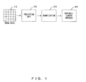
- the first conventional technology using a DPCM prediction device shown in FIG. 1 is knows as a common conventional image data compressing system.
- a prediction unit (DPCM) 210 predicts a level value of a pixel to be predicted from the line preceding a target pixel and the value of a preceding pixel, converts a prediction error from an actual pixel level value into a representative value, quantizes the value using a quantizer 310, and transmits a quantized value through a variable-length encoder 410 for assigning a code depending on the frequency of occurrence.
- DPCM prediction unit
- both high-frequency components and low-frequency components can be processed in a pixel unit for quantization and encoding.
- a prediction value is calculated on the basis of the value of the preceding line, an error is used during the next predicting process if the error occurs at any point. As a result, the prediction error propagates and causes image degradation along the line.
- a quantization table used by the quantizer 310 has the prediction error level value of -4 through 5 as a quantization prediction error of 0 (that is, a quantization table having a rough quantization width)
- the quantization prediction error is assumed as 0 although a prediction error of the level value of -4 through 4 occurs in any predicting process by the prediction unit (DPCM) 210. Therefore, the information that the prediction error has occurred cannot be included in the quantization result, and the prediction error remains as is. If the propagation of the prediction error occurs, a line unexpectedly occurs in the direction of the line in an image output as a process result, thereby causing image degradation.
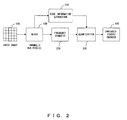
- the second conventional technology of compressing data by a JPEG (joint photographic experts group) and a MPEG (moving picture experts group) as shown in FIG. 2 is well known.
- the following patent documents 1 and 2 belong to the second conventional technology.
- the second conventional technology divides an input image 120 into blocks (normally 8*8 pixels) 130, applies DCT 220 to the block image, performs quantization 320 on a DCT coefficient, performs variable-length encoding 420 for assigning a code depending on the frequency of occurrence, and transmit the result.
- a DCT discrete cosine transfer
- a DCT discrete cosine transfer
- the DCT coefficient for a low frequency is precisely quantized, and the DCT coefficient for a high frequency is roughly quantized, thereby compressing natural images at a high compression rate at which image degradation can be inconspicuous.
- the image degradation is conspicuous on the high-frequency components such as a line and a character in map images (CG images).
- edge information extraction 230 is performed on a block to be compressed, there is the problem that correction and feedback cannot be performed by detecting the image degradation caused by a quantization error.
- the third conventional technology using a JPEG-LS is known as a conventional image data compressing system.
- the third conventional technology predicts a level value by a MED prediction device (Median edge detector), and directly encodes a prediction error.
- MED prediction device Median edge detector
- each process is heavy because, for example, a calculating process is required in encoding. Therefore the third conventional technology is unsuitable for real-time compression.
- Patent Document 1 Japanese Published Patent Application No. H10-126777
- Patent Document 2 Japanese Published Patent Application No. H6-350992
- estimated errors are used for signal transmission after quantization and coding.
- Each estimated value is derived from a reconstructed picture element signal formed in an adder. Separate, simultaneous subtractions for the signal taken at the output for the adder, as well as of the positive and negative adder limit values, from the respective picture element signal at the input thereby occur, whereby an overflow recognition device and a multiplexer provide that only the difference from the three differences formed up to this point are taken into consideration for quantization on the basis of the actual addition result, including no overflow, positive overflow and negative overflow.
- the present invention aims at provide an image compression device, method, and program capable of suppressing the image degradation between the lines caused by the quantization error when quantization tables are switched with the continuity of a prediction level value between a peripheral pixel and a line taken into account, and a image decompression device, method, and program capable of decompressing compressed image data.
- the image compression device according to the present invention is defined in claim 1
- the same level differences for a quantizing step occur in many cases between lines. Therefore, the level difference of the same value is evaluated, and if it is determined that a quantization error has propagated, the information is immediately fed back to perform precise quantization, thereby preventing the propagation of a prediction error occurring toward the plane having the completely same level differences such as CG images from vicinity of the edge.
- the quantizing step can be roughly or precisely set, thereby enhancing the compression efficiency with the image degradation avoided.
- An image compressing method and a program for compressing an image are a method and a program used for the image compression device provided with a prediction unit for predicting a pixel level value of a compressing target pixel.
- the program is defined in claim 2.
- the same level differences for a quantizing step occur in many cases between lines. Therefore, the level difference of the same value is evaluated, and if it is determined that a quantization error has propagated, the information is immediately fed back to perform precise quantization, thereby preventing the propagation of a prediction error occurring toward the plane having the completely same level differences such as CG images from vicinity of the edge.
- the quantizing step can be roughly or precisely set, thereby enhancing the compression efficiency with the image degradation avoided.
- the image decompression device of claim 3 and the image decompressing method set by a program of claim 4 according to the present invention decompress image data compressed by the image compression device in the reverse operation, it is evaluated in a pixel unit wether or not image degradation occurs during an inverse-quantizing process, and immediately feeding back the evaluation result to the inverse-quantization and inverse encoding for the next pixel, thereby momentarily (in several pixel units) correcting image degradation if it has occurred.
- the same level differences for a quantizing step occur in many cases between lines. Therefore, the level difference of the same value is evaluated, and if it is determined that a quantization error has propagated, the information is immediately fed back to perform precise inverse quantization, thereby preventing the propagation of a prediction error occurring toward the plane having the completely same level differences such as CG images from vicinity of the edge.
- the quantizing step can be roughly or precisely set, thereby enhancing the decompression efficiency with the image degradation avoided.
- the program for decompressing image data can perform an inverse operation to the operation of the program for compressing the image data
- a specific pixel level difference evaluating process or an absolute value sum evaluating process can be performed at a high speed like the program for compressing the image data, and can also perform the process of switching inverse-quantization tables.
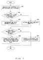
- FIG. 3 is a flowchart of the operation of the image compressing system according to the principle of the present invention.
- an adaptive quantizer 300 is provided, and when the quantizer quantizes the prediction error between the level value of a pixel to be predicted X and the prediction value X' by a prediction unit 200, the adaptive quantizer 300 adaptively selects a quantization table having a different quantizing step based on the continuity of the level value of a target pixel between the lines or the measurement of the peripheral pixel level difference. Then, the quantization is performed on the basis of the adaptively selected quantization table, and the result is transmitted through a variable-length encoder 400 for assigning a code depending on the frequency of occurrence.
- FIG. 4 is a block diagram of the configuration of the image data compression (encoding) device according to an embodiment of the present invention.
- image data 001 indicates a group of pixels to be compressed, and is extracted by an image processing device (not shown in the attached drawings) for digitally processing images.
- a compressing target pixel X (002) indicates a pixel to be compressed in the current step.
- FIG. 5 shows the arrangement of a compressing target pixel X and peripheral pixels (between the lines and in the preceding pixel) when the image format is an interlace image or a progressive image. In FIG. 5 , the lines are indicated by broken lines.
- a quantizer 003 quantizes the "prediction error" as a difference value between the compressing target pixel X (002) and a prediction value X' (006) on the basis of the quantization table selected according to the control signal from a quantization table switch module 017 for selecting a quantization table having a different quantizing step on the basis of the continuity of the level value of the target pixel (pixels A and B) between the lines and the measurement of the peripheral pixel level difference (the sum of the absolute values of the peripheral pixel level differences in this embodiment), and outputs a prediction error quantization value (also referred to simply as a quantization value) and a quantization number using a prediction error (X - X') as input.
- a prediction error quantization value also referred to simply as a quantization value
- FIG. 6A is a quantization table indicating the correspondence between the prediction error (X - X') and the quantization value and the quantization number, and the first quantization table including precise quantizing steps.
- FIG. 6B is a quantization table indicating the correspondence between the prediction error (X - X') and the quantization value and the quantization number, and the second quantization table including normal quantizing steps.
- FIG. 6C is a quantization table indicating the correspondence between the prediction error (X - X') and the quantization value and the quantization number, and the third quantization table including rough quantizing steps.
- the widths of the quantizing steps are narrower for smaller absolute values of prediction error, and wider for larger absolute values of prediction error for the following reason.
- a prediction error when a prediction error is small, it refers to a flat image which can be easily predicted.
- a prediction error when a prediction error is large, it refers to the vicinity of an edge which cannot be easily predicted. If there is an error in a flat portion, it can be easily detected by human eyes. Therefore, when a prediction error is small, the quantization error is reduced by narrowing the step width. It is desired that the minimum step width is 1 through 4.
- the step width of quantization is expanded to enhance the compression efficiency. It is desired that the step width is 24 through 32.
- the prediction error is large, the frequency of occurrence is basically low, and a large prediction error at the vicinity of an edge is not outstanding in comparison with an error at a flat portion. Therefore, the problem is not so serious although a step width is wide.
- the expanded step width for the improvement of compression efficiency requires more precise quantization on the flat portion.
- the absolute value of a prediction error is set to the minimum value of 0 and the maximum value of 11 or more in the first quantization table in the precise steps shown in FIG. 6A
- the absolute value of a prediction error is set to the minimum value of 2 and the maximum value of 21 or more in the second quantization table in the normal steps shown in FIG. 6B
- the absolute value of a prediction error is set to the minimum value of 4 and the maximum value of 41 or more in the third quantization table in the precise steps shown in FIG. 6C .
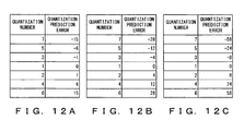
- FIGS. 12A, 12B, and 12C show the correspondence of the quantization values and the quantization numbers with reference to FIGS. 6A, 6B, and 6C . They are described later.
- three tables are exemplified, but the present invention is not limited to them, and it is necessary only to provide two or more quantization tables having different quantizing step widths.
- a variable-length encoder 004 receives a quantization number obtained from any of the quantization tables shown in FIGS. 6A, 6B, and 6C as input, and outputs a variable-length code.
- a compression code buffer 005 accumulates the output of the variable-length encoder 004.
- the prediction value 006 is calculated by a prediction unit 018.
- a one-line buffer for prediction 008 is configured by a buffer, for example, a shift register, for holding about one line for a quantization result for prediction.
- a peripheral pixel D (009) is positioned diagonally right above the compressing target pixel X, that is, one pixel after the compressing target pixel X in column but in the preceding line.
- a peripheral pixel C (010) is positioned above the compressing target pixel X, that is, in the same column as the compressing target pixel X but in the preceding line.
- a peripheral pixel B (011) is positioned diagonally left above the compressing target pixel X, that is, one pixel before the compressing target pixel X in column but in the preceding line.
- a peripheral pixel E (012) is left to the peripheral pixel B (011), that is, positioned two pixels before the compressing target pixel X in column but in the preceding line.
- each of the peripheral pixels D, C, B, and E is positioned two lines above the compressing target pixel X when the original image is the interlace image, and one line above the compressing target pixel X when the original image is the progressive image.
- a continuity evaluation result feedback module 013 measures the level difference on the basis of peripheral pixels A (007) and B (011), evaluates the continuity, and outputs a control signal 014 to use a precise quantization table (a first quantization table shown in FIG. 6A ) when the same level differences continue a predetermined number of times or more.
- the size lower than the image size is preferable because a switch to a precise quantization table is desired before image degradation is conspicuous. For example, in an image having 720 pixels in the horizontal direction, horizontal linear image degradation having a length of 6 pixels can be easily detected by human eyes. Therefore, a smaller number (four pixels in the present embodiment) is set.
- FIG. 7 is a flowchart of the operation of the continuity evaluation result feedback module 013 shown in FIG. 4 .
- step S041 shown in FIG. 7 the level difference B - A is compared with the preceding level difference.
- step S042 it is determined whether or not the level difference B - A is equal to the preceding level difference. If they are not equal to each other, the same value continuity counter is set to 1 in step S043, and control is passed to step S045. If they are equal to each other, control is passed to step S044, and the same value continuity counter is incremented by 1 in step S044.
- step S045 it is determined whether or not the counter value of the same value continuity counter is 4 or more. If the counter value is 4 or more, control is passed to step S046. In step S046, the control signal "000" indicating the quantization table of precise quantizing steps is transmitted, thereby terminating the process.
- the counter value in step S045 is 4 or more, the same level values continues a predetermined number of times or more, and it is considered that the prediction error propagates. Therefore, in this process, the error of the prediction level value can be more precisely detected by switching to a quantization table of more precise quantizing steps. Accordingly, when the prediction error actually propagates, the prediction error can be prevented from further propagating by switching to a quantization table in this process.
- step S047 control is passed to a peripheral level difference detection module 015, thereby terminating the process.
- control signal 014 indicates the control signal "000" referring to precise quantizing steps, or a control signal referring to the operation of the peripheral level difference detection module 015 for determining which quantization table is to be used again.
- the peripheral level difference detection module 015 calculates the absolute value of the sum of the peripheral pixel level differences, and compares the result with a threshold to determine which quantization table is to be used. After the determination, the module transmits a control signal 016. That is, the control signal 016 transmits the following control signal.
- Control signal 000 transmitted when a quantization table of precise quantizing steps is used
- Control signal 001 transmitted when a quantization table of normal quantizing steps is used
- Control signal 010 transmitted when a quantization table of rough quantizing steps is used
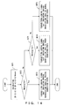
- FIG. 8 is a flowchart for explanation of the operation of the peripheral level difference determination module 015 shown in FIG. 4 .
- Ndsub as a sum of the absolute values of the level difference D - C, the level difference C - B, and the level difference B - A, and the level difference B - E is calculated.
- step S052 it is determined whether or not the Ndsub is 15 or less. If the Ndsub is 15 or less, control is passed to step S053.
- the control signal "000" indicating the quantization table of precise quantizing steps is transmitted, thereby terminating the process. That is, in the inactive image (flat image), any image degradation can be easily detected by human eyes. Therefore, a precise quantization table is used for the inactive image to perform high precision encoding.
- the value for determination of the Ndsub is 15 as a threshold in the description above, but the present invention is not limited to this value.
- the pixel level difference of 2 to 4 can be easily detected by human eyes. Since the sum of four absolute values of level differences is acquired in this embodiment, the total of the pixel level difference easily detected by human eyes is 8 (that is, 2 ⁇ 4) through 16 (that is, 4 ⁇ 4). Since the threshold used in the determination above is to suppress the propagation of error in an inactive image (flat image), a threshold (15 in the description above) is to be determined in the range from 8 to 16.
- step S054 If the Ndsub is 16 or more, control is passed to step S054, and it is determined in step S054 whether or not the Ndsub is 128 or more. If the Ndsub is 127 or less, control is passed to step S055. In step S055, the control signal "001" indicating the quantization table of normal quantizing steps is transmitted, thereby terminating the process. If the Ndsub is 128 or more, control is passed to step S056. In step S056, the control signal "010" indicating the quantization table of rough quantizing steps is transmitted, thereby terminating the process. That is, in a highly-active image (image having a small flat portion), some image degradation is not easily detected by human eyes. Therefore, high speed encoding can be realized by using a rough quantization table for the highly-active image.
- the value for determination of the Ndsub is 128 as a threshold in the description above, but the present invention is not limited to this value.
- the quantizing step width in a highly-active image is set to 24 through 32. Therefore, the sum of four absolute values of level differences is four times the set value, that is, the range from 96 to 128.
- a threshold is determined (128 in the description above), and a third quantization table of rough quantizing steps and a second quantization table of normal quantizing steps can be used.
- 3-bit control signals (000), (001), and (010) are associated as control signals, but any signal other than these control signals can be accepted so far as a quantization table of different quantizing steps can be specified.
- the quantization table is not limited to the above-mentioned quantization tables of precise, rough, or quantization table of normal quantizing steps, but four or more quantization tables can be provided, or only two types of quantization tables, that is, precise and rough tables, can be provided. In short, two or more types of quantization tables having different quantizing step widths can be provided.
- the quantization table switch module 017 outputs a control signal for switch of quantization tables according to two control signals 014 and 016 to the quantizer 003.
- the prediction unit 018 calculates a prediction value X' of the compressing target pixel X on the basis of the peripheral pixels A (007), B (011), and C (010).
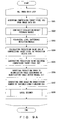
- FIG. 9A is a flowchart for explanation of the operation of the image data compression (encoding) device according to an embodiment of the present invention.
- FIG. 9B is a flowchart for explanation of the process of the "local decoder" in step S008 shown in FIG. 9A .
- S is short for "step”.
- S001 The compressing target pixel X (002) is acquired from the image data 001.
- S002 The continuity evaluation result feedback module 013 measures the level difference on the basis of the peripheral pixels A (007) and B (011), evaluates the continuity, and outputs the control signal 014 indicating the use of a precise quantization table when the same level differences continue a predetermined number of times or more to the quantization table switch module 017.
- the peripheral level difference detection module 015 detects a sum of absolute values of peripheral level differences, the sum of absolute values of peripheral level differences is evaluated, and a control signal 016 for determination of the quantization table is output to the quantization table switch module 017.
- the prediction unit 018 calculates the prediction value X' (006) of the compressing target pixel X (002).
- S005 the prediction value X' (006) is subtracted from the compressing target pixel X (002).
- a prediction error is input to the quantization table determined by the quantization table switch module 017 to calculate a prediction error quantization value (refer to FIGS. 6A through 6C ).
- S007 The variable-length encoder 004 generates a code on the basis of a quantization number.
- the code can be a Golomb code, or an arithmetic code.
- S010 The peripheral pixel C (010) is substituted for the peripheral pixel B (011) of the compressing target pixel.
- S011 The peripheral pixel D (009) is substituted for the peripheral pixel C (010) of the compressing target pixel.
- S012 The peripheral pixel D (009) of the next compressing target pixel is acquired from the one-line buffer for prediction 008.
- S013 The peripheral pixel A (007) is substituted for the one-line buffer for prediction 008.
- S014 The quantization value and the prediction value are added up, and the sum is substituted for the peripheral pixel A (007) of the next compressing target pixel.
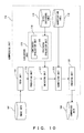
- FIG. 10 is a block diagram showing the configuration of the system of the image data compression device according to an embodiment of the present invention, and represents a block diagram showing the functions of the contents described above.
- the image data compression device first inputs image data 102 to be compressed to a compressing unit 110, the compressing unit 110 first reads each line of the image data 102 by read unit 111, extracts a pixel to be compressed, and inputs the extracted compressing target pixel to a predicting unit 112.
- the predicting unit 112 calculates a prediction error by subtracting the prediction value of the compressing target pixel that has been predicted by a prediction device from the compressing target pixel level, a continuity evaluation unit 114 of a evaluation unit 113 corresponding to the continuity evaluation result feedback module 013 shown in FIG. 4 evaluates whether or not the level difference between the two specific peripheral pixel relating to the compressing target pixel continue. If the same level differences continue a predetermined number of times or more, a control signal for a use of a precise quantization table 119 as shown in FIG. 6A is generated. In addition, a peripheral evaluation unit 115 of the evaluation unit 113 corresponding to the peripheral level difference detection module 015 shown in FIG.
- a level difference table 116 for management after associating the level difference with the information about a quantization table to be used, evaluates the sum of the absolute values of the peripheral pixel level differences, and inputs a control signal indicating which level of quantization table 119 is to be used to a switching unit 117.
- the switching unit 117 corresponding to the quantization table switch module 017 instructs a quantizing unit 118 to switch the quantization table 119 according to the input control signal.
- the quantizing unit 118 switches the quantization table 119, calculates a prediction error quantization value using the switched quantization table 119, and inputs the calculation result as the output of the quantizing unit 118 to an encoding unit 120 corresponding to the variable-length encoder 004.
- the encoding unit 120 generates a compression code on the basis of the input prediction error quantization value, accumulates the generated compression code as the output of the compressing unit 110, and obtains compressed data 104.
- the process by the image data compression device shown in FIG. 10 can be performed by a computer.
- the hardware resources of the computer can be various registers, arithmetic units including an ALU, RAM, ROM, I/O, etc. although not shown in the attached drawings.
- the above-mentioned modules, prediction device, quantizers including a quantization table, encoder, etc. can be incorporated into one unit as a chip of LSI and can be used as an image data compression device in various applications for processing two types of image data having different characteristics.
- each pixel is quantized and coded, and each pixel is evaluated as to whether or not image degradation has occurred in the quantizing process, and the result is immediately fed back (switching quantization tables) in quantizing and encoding the next pixel. If image degradation has occurred by quantization error, a quantizing process is performed by switching a quantization table to a quantization table of precise quantizing steps, thereby solving (or suppressing) the problem of the quantization error and immediately (in several pixel units) correcting the image degradation if it has occurred.
- the quantization table is switched to perform precise quantization, thereby preventing the propagation of prediction error that causes a line which does not originally exist in an image, but occurs at the vicinity of an edge.
- the image degradation in a flat image that indicates small fluctuations in level difference can be easily detected outstandingly.
- the image degradation in a highly-active image is not easily detected. Therefore, by calculating a sum of the absolute values of the level differences as the activity levels of the pixels in the preceding and current lines, the quantizing steps can be rough or precise to enhance the compression efficiency with the image degradation suppressed.
- a simple device as a counter can detect whether or not the same level differences continuously occur in a specific pixel, and a quantization table for precise quantization can be selected when the same level differences occur a predetermined number of times or more, for example, continuously four times, then the image degradation to be caused in the direction of long lines can be corrected before it occurs.
- a sum of the absolute values of the peripheral pixel level differences of the compressing target pixel is calculated using a prediction buffer for holding 1 line of pixel level values.
- a control signal indicating which quantization table is to be used is transmitted to a quantization table switching module. Therefore, feedback can be immediately applied to the quantizer on the basis of the activity level (peripheral pixel level difference) around the compressing target pixel.
- a control signal for switch a quantization table is used in switching quantization tables. Therefore, depending on the continuity of the pixel level difference and the activity level around the compressing target pixel, three types of quantization tables having different levels of quantization, that is, a precise quantization table, a normal quantization table, and a rough quantization table, can be selectively used. Furthermore, it is obvious that, when more precise control is to be performed, three or more types of quantization tables can be selectively used for the same effect.
- the image compression device processes image data passing as a stream in a frame unit when an image to be processed is a progressive image, and in the order from top to bottom of he screen in a field unit when the image to be processed is an interlace image.
- a predetermined size of the compressed data after compression encoding is put in a packet and transferred in accordance with the transmission rules of a transmission line to which the present device is connected.
- FIG. 11 is a block diagram showing the configuration of the image data decompression (decoding) device according to an embodiment of the present invention.
- a compression code 031 refers to a compression code of image data variable-length encoded as shown in FIG. 4 .
- an inverse encoder 032 receives a compressed code of the variable-length encoded image data, and outputs a quantization number corresponding to the code.
- An inverse quantizer 033 receives the quantization number and outputs a prediction error quantization value X (034).
- FIG. 12A is an inverse quantization table showing the correspondence between the quantization number assigned to the inverse quantizer 033 and the quantization value (prediction error quantization value), and is a first inverse quantization table having precise quantizing steps.
- FIG. 12B is an inverse quantization table showing the correspondence between the quantization number assigned to the inverse quantizer 033 and the quantization value (prediction error quantization value), and is a second inverse quantization table having normal quantizing steps.
- FIG. 12C is an inverse quantization table showing the correspondence between the quantization number assigned to the inverse quantizer 033 and the quantization value (prediction error quantization value), and is a third inverse quantization table having rough quantizing steps. The correspondence between the quantization values and the quantization numbers shown in FIGS.
- the arrangement between the decompressing target pixel X and the peripheral pixel (between the lines and the preceding pixel) is the same as the arrangement between the compressing target pixel and the peripheral pixel (between the lines and the preceding pixel) shown in FIG. 5 .
- the pixel to be compressed shown in FIG. 5 is replaced with the pixel to be decompressed.
- the prediction error quantization value X (034) is added to a prediction value X' (036) calculated by a prediction device 048 to obtain a decompressed image data 035, and can be a peripheral pixel A (037) of the next decompressing target pixel.
- the peripheral pixel A (037) is left to the decompressing target pixel as the peripheral pixel A shown in FIG. 5 .
- a one-line buffer for prediction 038 is configured by a buffer, for example, a shift register, for holding about one line for a quantization result for prediction.
- a peripheral pixel D (039) is located diagonally right above (in the preceding line) the decompressing target pixel.
- a peripheral pixel C (040) is located above (in the preceding line) the decompressing target pixel.
- a peripheral pixel B (041) is located diagonally left above (in the preceding line) the decompressing target pixel.
- a peripheral pixel E (042) is located left to the peripheral pixel B (041) in the preceding line.
- a continuity evaluation result feedback module 043 measures the level difference on the basis of peripheral pixels A (037) and B (041), evaluates the continuity, and outputs a control signal 044 to use a precise quantization table (a first inverse quantization table shown in FIG. 12A ) when the same level differences continue a predetermined number of times or more.
- the size lower than the image size is preferable because a switch to a precise inverse quantization table is desired before image degradation is conspicuous. For example, in an image having 720 pixels in the horizontal direction, horizontal linear image degradation having a length of 6 pixels can be easily detected by human eyes. Therefore, a smaller number (four pixels in the present embodiment) is set.
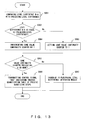
- FIG. 13 is a flowchart of the operation of the continuity evaluation result feedback module 043 shown in FIG. 11 .
- step S061 shown in FIG. 13 the level difference B - A is compared with the preceding level difference.
- step S062 it is determined whether or not the level difference B - A is equal to the preceding level difference. If they are not equal to each other, the same value continuity counter is set to 1 in step S063, and control is passed to step S065. If they are equal to each other, control is passed to step S064, and the same value continuity counter is incremented by 1 in step S064.
- step S065 it is determined whether or not the counter value of the same value continuity counter is 4 or more. If the counter value is 4 or more, control is passed to step S066.
- step S066 the control signal "000" indicating the inverse quantization table of precise quantizing steps is transmitted, thereby terminating the process.
- control is passed to step S067.
- step S067 control is passed to a peripheral level difference detection module 045, thereby terminating the process.
- control signal 044 indicates the control signal "000" referring to precise quantizing steps, or a control signal referring to the operation of the peripheral level difference detection module 045 for determining which inverse quantization table is to be used again.
- the peripheral level difference detection module 045 calculates the absolute value of the sum of the peripheral pixel level differences, and compares the result with a threshold to determine which inverse quantization table is to be used. After the determination, the module transmits a control signal 046. That is, the control signal 046 transmits the following control signal.
- Control signal 000 transmitted when an inverse quantization table of precise quantizing steps is used
- Control signal 001 transmitted when an inverse quantization table of normal quantizing steps is used
- Control signal 010 transmitted when an inverse quantization table of rough quantizing steps is used
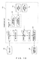
- FIG. 14 is a flowchart for explanation of the operation of the peripheral level difference determination module 045 shown in FIG. 11 .
- Ndsub as a sum of the absolute values of the level difference D - C, the level difference C - B, and the level difference B - A, and the level difference B - E is calculated.
- step S072 it is determined whether or not the Ndsub is 15 or less. If the Ndsub is 15 or less, control is passed to step S073.
- the control signal "000" indicating the inverse quantization table of precise quantizing steps is transmitted, thereby terminating the process.
- step S074 determines whether or not the Ndsub is 128 or more. If the Ndsub is 127 or less, control is passed to step S075. In step S075, the control signal "001" indicating the inverse quantization table of normal quantizing steps is transmitted, thereby terminating the process. If the Ndsub is 128 or more, control is passed to step S076. In step S076, the control signal "010" indicating the inverse quantization table of rough quantizing steps is transmitted, thereby terminating the process.
- the value of the threshold for determination of the Ndsub is not limited to 15 or 128, or a value in a desired range is similarly determination as in the compressing process described above.
- 3-bit control signals (000), (001), and (010) are associated as control signals, but any signal other than these control signals can be accepted so far as an inverse quantization table of different quantizing steps can be specified.
- the inverse quantization table is not limited to the above-mentioned inverse quantization tables of precise, rough, or inverse quantization table of normal quantizing steps, but four or more inverse quantization tables can be provided, or only two types of inverse quantization tables, that is, precise and rough inverse tables, can be provided. In short, two or more types of inverse quantization tables can be provided corresponding to the quantization tables on the above-mentioned image data compression device.
- the quantization table switch module 047 outputs a control signal for switch of inverse quantization tables according to two control signals 044 and 046 to the inverse quantizer 033.
- the prediction device 048 calculates a prediction value X' of the decompressing target pixel X on the basis of the peripheral pixels A (037), B (041), and C (040).
- FIG. 15A is a flowchart for explanation of the operation of the image data decompression (decoding) device according to an embodiment of the present invention.
- FIG. 15B is a flowchart for explanation of the process of the "local decoder" in step S028 shown in FIG. 15A .
- S is short for "step”.
- S021 The compression code 031 is input to the inverse encoder 032 to output a quantization number.
- S023 The peripheral level difference detection module 045 detects a sum of absolute values of peripheral level differences, the sum of absolute values of peripheral level differences is evaluated, and a control signal 046 for determination of the inverse quantization table to the quantization table switch module 047.
- S024 The prediction device 048 calculates the prediction value X' of the decompressing target pixel X.
- S025 A quantization number is input to the inverse quantization table determined by the quantization table switching module 047, and a prediction error quantization value is calculated.
- S026 The prediction value is added to the prediction error quantization value.
- S027 The sum in S026 is set as decompressed image data.
- S028 To decompress the next pixel, the peripheral pixels A (037), B (040), C (040), and the buffer for prediction 038 are updated (local decoder).
- S029 The peripheral pixel B (041) is substituted for the peripheral pixel E (042) of the decompressing target pixel.
- S030 The peripheral pixel C (040) is substituted for the peripheral pixel B (041) of the decompressing target pixel.
- S031 The peripheral pixel B (039) is substituted for the peripheral pixel C (040) of the decompressing target pixel.
- S032 The peripheral pixel D (039) of the next decompressing target pixel is acquired from the one-line buffer for prediction 038.
- S033 The peripheral pixel A (037) is substituted for the one-line buffer for prediction 038.
- S034 The prediction error quantization value and the prediction value are added up, and the sum is substituted for the peripheral pixel A (037) of the next decompressing target pixel.
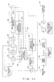
- FIG. 16 is a block diagram showing the configuration of the system of the image data decompression device according to an embodiment of the present invention, and represents the functions of the contents described above.
- the image data decompression device inputs compressing data 202 as the output of the image data compression device to the decompressing unit 210.
- the decompressing unit 210 first inputs the image data 202 to an inverse encoding unit 211 corresponding to the inverse encoder 032 shown in FIG. 11 , obtains a quantization number from the inverse encoding unit 211, and inputs the quantization number to the inverse quantizing unit 212 corresponding to the inverse quantizer 033.
- a continuity evaluation unit 213 corresponding to the continuity evaluation result feedback module 043 shown in FIG. 11 in the evaluation unit 212 evaluates whether or not the level difference of two specific peripheral pixels relating to the decompressing target pixel continuously appears. If the same level differences continues a predetermined number of times, a control signal for use of a precise inverse quantization table 218 is generated.
- a peripheral evaluation unit 214 corresponding to the peripheral level difference detection module 045 of the environment unit 212 detects a sum of the absolute values of the level differences of two peripheral pixels including the peripheral pixels of the pixel for which a prediction value of a decompressing target pixel is calculated, refers to a level difference table 215 for management by association between the level difference and the information about the quantization table to be used, evaluates the sum of the absolute values of the peripheral pixel level differences, and inputs the control signal indicating what level of the inverse quantization table 218 is to be used to a switching unit 216.
- the switching unit 216 corresponding to the quantization table switch module 047 instructs an inverse quantizing unit 217 to switch the inverse quantization table 218 according to the input control signal.
- the inverse quantizing unit 217 switches the inverse quantization table 218, calculates a prediction error quantization value using the switched quantization table 218, and inputs the calculation result to a predicting unit 219.
- the predicting unit 219 adds up the prediction value of the decompressing target pixel predicted by the prediction device and the prediction error quantization value calculated using the inverse quantization table 218 to observe a decompressed pixel value, accumulates the value, and obtain decompressed (image) data 204.
- the process by the image data decompression device shown in FIG. 16 can be performed by a computer.
- the hardware resources of the computer can be various registers, arithmetic units including an ALU, RAM, ROM, I/O, etc. although not shown in the attached drawings.
- the above-mentioned modules, prediction device, inverse quantizers including an inverse quantization table, inverse encoder, etc. can be incorporated into one unit as a chip of LSI and can be used as an image data decompression device in various applications for processing two types of image data having different characteristics.
- image data can be decompressed by switching an inverse quantization table on the decompressing side as well as the compressing side.
- the image data compression device and the image data decompression device according to the present invention can be read as one-chip LSI to be loaded into a desired application equipment, and can be applied to, for example, a car-mounted video data transmission system including a car navigation system, various amusement (game, animation, etc.) equipment.
- a display is provided on the rear side to supply video different from the front side. Therefore, the image data processed by the video data processing device implemented on the front side can be compressed and transmitted to the rear side. On the rear side, the transmitted image data is decompressed and displayed. When image data is relayed, the compressing and decompressing processes are repeated at each relay point.
Landscapes
- Engineering & Computer Science (AREA)
- Multimedia (AREA)
- Signal Processing (AREA)
- Compression Or Coding Systems Of Tv Signals (AREA)
- Compression, Expansion, Code Conversion, And Decoders (AREA)
- Compression Of Band Width Or Redundancy In Fax (AREA)
Claims (4)
- Bildkomprimierungsvorrichtung (110) mit einer Prädiktionseinheit (112, 018) zum Vorhersagen eines Wertes eines zu komprimierenden Zielpixels (002) aus peripheren Werten mit Bezug auf das Zielpixel, und mit einer Quantisierungseinheit (118, 003) zum Quantisieren einer Prädiktionsabweichung zwischen dem Prädiktionswert (006), der von der Prädiktionseinheit ausgegeben wird, und dem Wert des Zielpixels (002) unter Verwendung eines Quantisierungsschritts, der mit einer Quantisierungstabelle und einer Quantisierungsschalteinheit (117, 017) bestimmt wird, dadurch gekennzeichnet, dass sie Folgendes umfasst:- einen Zwischenspeicher (008), der Stufenwerte für Pixel enthält, die komprimierte Pixel in einer ersten Reihe, die das Zielpixel (002) umfasst, und komprimierte Pixel in einer zweiten Reihe, die vor der ersten Reihe komprimiert wird, umfassen, wobei ein Stufenwert eine Summe des Prädiktionswertes und des Quantisierungswertes der Prädiktionsabweichung ist, die einem komprimierten Pixel entspricht, wobei die Werte einen zweiten Stufenwert, einen dritten Stufenwert, einen vierten Stufenwert und einen fünften Stufenwert umfassen,-- wobei der zweite Stufenwert einem zweiten komprimierten Pixel (011) in derselben Spaltenposition in der zweiten Reihe wie ein erstes komprimiertes Pixel (007) entspricht, das unmittelbar vor dem Zielpixel in der ersten Reihe komprimiert wird und einen ersten Stufenwert aufweist,-- wobei der dritte Stufenwert einem dritten komprimierten Pixel (010) in derselben Spaltenposition in der zweiten Reihe wie das Zielpixel entspricht, und-- wobei der vierte Stufenwert einem vierten komprimierten Pixel (009) entspricht, das unmittelbar nach dem dritten Pixel in der zweiten Reihe komprimiert wird,-- wobei der fünfte Stufenwert einem fünften komprimierten Pixel (012) entspricht, das unmittelbar vor dem zweiten komprimierten Pixel in der zweiten Reihe komprimiert wird,- eine spezifische Einheit (113, 013) zum Auswerten der Pixelstufendifferenz, die Folgendes umfasst:-- Mittel zum Berechnen eines Differenzwertes zwischen dem zweiten Stufenwert und dem ersten Stufenwert,-- einen Zähler, der dazu geeignet ist, um einen Zählerwert zu inkrementieren, wenn der Differenzwert der gleiche ist wie der Differenzwert zwischen dem fünften Stufenwert und dem Stufenwert des Pixels, das unmittelbar vor dem ersten Pixel in der ersten Reihe komprimiert wird, und der dazu geeignet ist, um ein Anweisungssignal (014), um die Quantisierungstabelle umzuschalten, um die Quantisierung in einem kleineren Quantisierungsschritt auszuführen, an die Quantisierungsschalteinheit (117, 017) auszugeben, wenn der Zählerwert gleich oder höher als ein erster Schwellenwert ist;- eine Einheit (115, 015) zum Auswerten einer Summe absoluter Werte, zum-- wenn der Zählerwert kleiner als der erste Schwellenwert ist, Erzielen aus dem Zwischenspeicher (008) des zweiten Stufenwertes, des dritten Stufenwertes und des vierten Stufenwertes und des fünften Stufenwertes, und-- Berechnen einer Gesamtsumme absoluter Werte von Differenzenund--- zwischen dem vierten und dem dritten Stufenwert und--- zwischen dem dritten und dem zweiten Stufenwert und--- zwischen dem zweiten und dem ersten Stufenwert und--- zwischen dem zweiten und dem fünften
Stufenwert,-- Vergleichen der Gesamtsumme mit einem zweiten Schwellenwert und-- Ausgeben des Anweisungssignals, um die Quantisierungstabelle umzuschalten, um die Quantisierung in einem kleineren Quantisierungsschritt auszuführen, wenn die Gesamtsumme als Ergebnis der Auswertung kleiner als der zweite Schwellenwert ist, und Ausgeben eines Anweisungssignals, um die Quantisierungstabelle auf einen größeren Quantisierungsschritt umzuschalten, wenn die Gesamtsumme größer als der zweite Schwellenwert ist;- wobei die Quantisierungsumschalteinheit (117, 017) dazu geeignet ist, um die Quantisierungstabelle für einen Quantisierungsschritt der Quantisierungseinheit (118) gemäß dem ausgegebenen Anweisungssignal umzuschalten. - Computerprogramm zum Vorhersagen eines Wertes eines zu komprimierenden Zielpixels (002) aus peripheren Werten mit Bezug auf das Zielpixel, und zum Quantisieren einer Prädiktionsabweichung zwischen dem Prädiktionswert (006), der von der Prädiktionseinheit ausgegeben wird, und dem Wert des Zielpixels (002) unter Verwendung eines Quantisierungsschritts, der mit einer Quantisierungstabelle bestimmt wird, wobei das Computerprogramm dadurch gekennzeichnet ist, dass es Software-Code umfasst, der Stufenwerte für Pixel verwendet, die komprimierte Pixel in einer ersten Reihe, die das Zielpixel (002) umfasst, und komprimierte Pixel in einer zweiten Reihe, die vor der ersten Reihe komprimiert wird, umfassen, wobei ein Stufenwert eine Summe des Prädiktionswertes und des Quantisierungswertes der Prädiktionsabweichung ist, die einem komprimierten Pixel entspricht, wobei die Stufenwerte einen ersten Stufenwert, einen zweiten Stufenwert, einen dritten Stufenwert, einen vierten Stufenwert und einen fünften Stufenwert umfassen,- wobei der erste Stufenwert einem ersten komprimierten Pixel (007) entspricht, das unmittelbar vor dem Zielpixel in der ersten Reihe komprimiert wird,- wobei der zweite Stufenwert einem zweiten komprimierten Pixel (011) in derselben Spaltenposition in der zweiten Reihe wie das erste komprimierte Pixel entspricht,- wobei der dritte Stufenwert einem dritten komprimierten Pixel (010) in derselben Spaltenposition in der zweiten Reihe wie das Zielpixel (007) entspricht,- wobei der vierte Stufenwert einem vierten komprimierten Pixel (009) entspricht, das unmittelbar nach dem dritten Pixel in der zweiten Reihe komprimiert wird,- wobei der fünfte Stufenwert einem fünften komprimierten Pixel (012) entspricht, das unmittelbar vor dem zweiten komprimierten Pixel in der zweiten Reihe komprimiert wird, und der Software-Code dazu geeignet ist, um die folgenden Schritte auszuführen:- Berechnen eines ersten Differenzwertes zwischen dem zweiten Stufenwert und dem ersten Stufenwert, und- (S002) Inkrementieren eines Zählerwertes, wenn der Differenzwert der gleiche ist wie der Differenzwert zwischen dem fünften Stufenwert und dem Stufenwert des Pixels, das unmittelbar vor dem ersten Pixel in der ersten Reihe komprimiert wird, und Umschalten der Quantisierungstabelle, um die Quantisierung in einem kleineren Quantisierungsschritt auszuführen, wenn der Zählerwert gleich oder höher als ein erster Schwellenwert ist;- (S003) wenn der Zählerwert kleiner als der erste Schwellenwert ist, Erzielen des zweiten Stufenwertes, des dritten Stufenwertes, des vierten Stufenwertes und des fünften Stufenwertes, und Berechnen einer Gesamtsumme absoluter Werte von Differenzen-- zwischen dem vierten und dem dritten Stufenwert und-- zwischen dem dritten und dem zweiten Stufenwert und-- zwischen dem zweiten und dem ersten Stufenwert und-- zwischen dem zweiten und dem fünften Stufenwert,- Vergleichen der Gesamtsumme mit einem zweiten Schwellenwert und Ausgeben des Anweisungssignals, um die Quantisierungstabelle umzuschalten, um eine Quantisierung in einem kleineren Quantisierungsschritt auszuführen, wenn die Gesamtsumme als Ergebnis der Auswertung kleiner als der zweite Schwellenwert ist, und eines Anweisungssignals, um die Quantisierungstabelle auf einen größeren Quantisierungsschritt umzuschalten, wenn die Gesamtsumme größer als der zweite Schwellenwert ist; und- (S006) Quantisieren der Prädiktionsabweichung zwischen dem Prädiktionswert und dem Wert des Zielpixels unter Verwendung eines vorherbestimmten Quantisierungsschritts, der von der Quantisierungstabelle eingestellt wird.
- Bilddekomprimierungsvorrichtung (210) mit einer Prädiktionseinheit (219, 048) zum Vorhersagen eines Wertes eines zu dekomprimierenden Zielpixels (036) aus peripheren Werten mit Bezug auf das Zielpixel (036), und mit einer Umkehrquantisierungseinheit (217, 033) zum Umkehrquantisieren einer Quantisierungszahl, die von einer Bildkomprimierungsvorrichtung unter Verwendung eines vorherbestimmten Quantisierungsschritts im Voraus berechnet wird, und Berechnen einer Summe des Prädiktionswertes, der von der Prädiktionseinheit (219, 048) ausgegeben wird, und des Quantisierungswertes der Prädiktionsabweichung, der mit einer Umkehrquantisierungstabelle bestimmt wird und von der Umkehrquantisierungseinheit (217, 033) ausgegeben wird, und mit einer Einheit (216, 047) zum Umschalten der Quantisierungstabelle, und dadurch gekennzeichnet, dass sie Folgendes umfasst:- einen Zwischenspeicher (038), der Dekomprimierungswerte für Pixel enthält, die dekomprimierte Pixel in einer ersten Reihe, die das Zielpixel (036) umfasst, und dekomprimierte Pixel in einer zweiten Reihe, die vor der ersten Reihe dekomprimiert wird, umfassen, wobei ein Dekomprimierungswert eine Summe des Prädiktionswertes und des Quantisierungswertes der Prädiktionsabweichung, die einem dekomprimierten Pixel entspricht, ist, wobei die Dekomprimierungswerte einen zweiten Dekomprimierungswert, einen dritten Dekomprimierungswert, einen vierten Dekomprimierungswert und einen fünften Dekomprimierungswert umfassen,-- wobei der zweite Dekomprimierungswert einem zweiten dekomprimierten Pixel (041) in derselben Spaltenposition in der zweiten Reihe wie ein erstes dekomprimiertes Pixel (037) entspricht, das unmittelbar vor dem Zielpixel (036) in der ersten Reihe dekomprimiert wird und einen ersten Dekomprimierungswert aufweist,-- wobei der dritte Dekomprimierungswert einem dritten dekomprimierten Pixel (040) in derselben Spaltenposition in der zweiten Reihe wie das Zielpixel (036) entspricht,-- wobei der vierte Dekomprimierungswert einem vierten dekomprimierten Pixel (039) entspricht, das unmittelbar nach dem dritten Pixel in der zweiten Reihe dekomprimiert wird, und-- wobei der fünfte Dekomprimierungswert einem fünften dekomprimierten Pixel (042) entspricht, das unmittelbar vor dem zweiten dekomprimierten Pixel in der zweiten Reihe dekomprimiert wird,- eine spezifische Einheit (212, 043) zum Auswerten einer Pixelstufendifferenz, die Folgendes umfasst:-- Mittel zum Berechnen eines Differenzwertes zwischen dem zweiten Dekomprimierungswert und dem ersten Dekomprimierungswert,-- einen Zähler, der dazu geeignet ist, um einen Zählerwert zu inkrementieren, wenn der Differenzwert der gleiche ist wie der Differenzwert zwischen dem fünften Dekomprimierungswert und dem Dekomprimierungswert des Pixels, das unmittelbar vor dem ersten Pixel in der ersten Reihe dekomprimiert wird,
und die dazu geeignet ist, um ein Anweisungssignal (046), um die Quantisierungstabelle umzuschalten, um die Umkehrquantisierung in dem kleineren Quantisierungsschritt auszuführen, an die Quantisierungsschalteinheit (216, 047) auszugeben, wenn der Zählerwert gleich oder höher als ein erster Schwellenwert ist;- eine Einheit (214, 045) zum Auswerten einer Summe absoluter Werte, zum-- wenn der Zählerwert kleiner als der erste Schwellenwert ist, Erzielen aus dem Zwischenspeicher (038) des zweiten Dekomprimierungswertes, des dritten Dekomprimierungswertes, des vierten Dekomprimierungswertes und des fünften Dekomprimierungswertes, und-- Berechnen einer Gesamtsumme absoluter Werte von Differenzen--- zwischen dem vierten und dem dritten Dekomprimierungswert und--- zwischen dem dritten und dem zweiten Dekomprimierungswert und--- zwischen dem zweiten und dem ersten Dekomprimierungswert und--- zwischen dem zweiten und dem fünften Dekomprimierungswert, und-- Vergleichen der Gesamtsumme mit einem zweiten Schwellenwert, und-- Ausgeben des Anweisungssignals, um die Umkehrquantisierungstabelle umzuschalten, um eine Quantisierung in einem kleineren Quantisierungsschritt auszuführen, wenn die Gesamtsumme als Ergebnis der Auswertung kleiner als der zweite Schwellenwert ist, und Ausgeben eines Anweisungssignals, um die Umkehrquantisierungstabelle auf einen größeren Quantisierungsschritt umzuschalten, wenn die Gesamtsumme größer als der zweite Schwellenwert ist;- wobei die Quantisierungsumschalteinheit (216, 047) dazu geeignet ist, um die Umkehrquantisierungstabelle umzuschalten, um die Quantisierung in einem kleineren Quantisierungsschritt der Umkehrquantisierungseinheit (217, 033) gemäß dem ausgegebenen Anweisungssignal auszuführen. - Computerprogramm zum Vorhersagen eines Wertes eines zu dekomprimierenden Zielpixels (036) aus peripheren Werten mit Bezug auf das Zielpixel (036), und zum Umkehrquantisieren einer Quantisierungszahl, die von einer Bildkomprimierungsvorrichtung unter Verwendung eines vorherbestimmten Quantisierungsschritts im Voraus berechnet wird, und Berechnen einer Summe eines Prädiktionswertes und eines Quantisierungswertes der Prädiktionsabweichung, der mit einer Umkehrquantisierungstabelle bestimmt wird, wobei das Computerprogramm dadurch gekennzeichnet ist, dass es Software-Code umfasst, der Dekomprimierungswerte für Pixel verwendet, die dekomprimierte Pixel in einer ersten Reihe, die das Zielpixel (036) umfasst, und dekomprimierte Pixel in einer zweiten Reihe, die vor der ersten Reihe dekomprimiert wird, umfassen, wobei ein Dekomprimierungswert eine Summe des Prädiktionswertes und des Quantisierungswertes der Prädiktionsabweichung ist, die einem dekomprimierten Pixel entspricht, und wobei die Dekomprimierungswerte einen ersten Dekomprimierungswert, einen zweiten Dekomprimierungswert, einen dritten Dekomprimierungswert, einen vierten Dekomprimierungswert und einen fünften Dekomprimierungswert umfassen,- wobei der erste Dekomprimierungswert einem ersten dekomprimierten Pixel (037) entspricht, das unmittelbar vor dem Zielpixel (036) in der ersten Reihe dekomprimiert wird,- wobei der zweite Dekomprimierungswert einem zweiten dekomprimierten Pixel (041) in derselben Spaltenposition in der zweiten Reihe wie das erste dekomprimierte Pixel entspricht,- wobei der dritte Dekomprimierungswert einem dritten dekomprimierten Pixel (040) in derselben Spaltenposition in der zweiten Reihe wie das Zielpixel entspricht,- wobei der vierte Dekomprimierungswert einem vierten dekomprimierten Pixel (039) entspricht, das unmittelbar nach dem dritten Pixel in der zweiten Reihe dekomprimiert wird,- wobei der fünfte Dekomprimierungswert einem fünften dekomprimierten Pixel (042) entspricht, das unmittelbar vor dem zweiten dekomprimierten Pixel in der zweiten Reihe dekomprimiert wird, undwobei der Software-Code dazu geeignet ist, um folgende Schritte auszuführen:- Berechnen eines ersten Differenzwertes zwischen dem zweiten Dekomprimierungswert und dem ersten Dekomprimierungswert;- Inkrementieren eines Zählerwertes, wenn der Differenzwert der gleiche ist wie der Differenzwert zwischen dem fünften Dekomprimierungswert und dem Dekomprimierungswert des Pixels, das unmittelbar vor dem ersten Pixel in der ersten Reihe dekomprimiert wird,- Umschalten der Umkehrquantisierungstabelle, um eine Quantisierung in einem kleineren Quantisierungsschritt auszuführen, wenn der Zählerwert gleich oder höher ist als ein erster Schwellenwert;- (S012) wenn der Zählerwert kleiner als der erste Schwellenwert ist, Erzielen des zweiten Dekomprimierungswertes, des dritten Dekomprimierungswertes, des vierten Dekomprimierungswertes und des fünften Dekomprimierungswertes, und Berechnen einer Gesamtsumme absoluter Werte von Differenzen-- zwischen dem vierten und dem dritten Dekomprimierungswert und-- zwischen dem dritten und dem zweiten Dekomprimierungswert und-- zwischen dem zweiten und dem ersten Dekomprimierungswert und-- zwischen dem zweiten und dem fünften
Dekomprimierungswert, und Vergleichen der Gesamtsumme mit einem zweiten Schwellenwert und- Ausgeben des Anweisungssignals, um die Umkehrquantisierungstabelle umzuschalten, um eine Quantisierung in einem kleineren Quantisierungsschritt auszuführen, wenn die Gesamtsumme als Ergebnis der Auswertung kleiner als der zweite Schwellenwert ist, und eines Anweisungssignals, um die Umkehrquantisierungstabelle auf einen größeren Quantisierungsschritt umzuschalten, wenn die Gesamtsumme größer als der zweite Schwellenwert ist, und- Umkehrquantisieren einer Quantisierungszahl und Berechnen einer Summe eines Prädiktionswertes und eines Quantisierungswertes der Prädiktionsabweichung, der mit der Umkehrquantisierungstabelle bestimmt wird.
Applications Claiming Priority (2)
| Application Number | Priority Date | Filing Date | Title |
|---|---|---|---|
| JP2006138071 | 2006-05-17 | ||
| PCT/JP2006/316107 WO2007132539A1 (ja) | 2006-05-17 | 2006-08-16 | 画像圧縮装置、圧縮方法及びプログラム並びに画像復元装置、復元方法及びプログラム |
Publications (3)
| Publication Number | Publication Date |
|---|---|
| EP2034741A1 EP2034741A1 (de) | 2009-03-11 |
| EP2034741A4 EP2034741A4 (de) | 2010-12-29 |
| EP2034741B1 true EP2034741B1 (de) | 2013-08-14 |
Family
ID=38693642
Family Applications (1)
| Application Number | Title | Priority Date | Filing Date |
|---|---|---|---|
| EP20060796466 Not-in-force EP2034741B1 (de) | 2006-05-17 | 2006-08-16 | Bildkomprimierungseinrichtung, komprimierungsverfahren, programm und bilddekomprimierungseinrichtung, dekomprimierungsverfahren und programm |
Country Status (6)
| Country | Link |
|---|---|
| US (1) | US8045814B2 (de) |
| EP (1) | EP2034741B1 (de) |
| JP (1) | JP4709900B2 (de) |
| KR (1) | KR100980354B1 (de) |
| CN (1) | CN101444103B (de) |
| WO (1) | WO2007132539A1 (de) |
Families Citing this family (27)
| Publication number | Priority date | Publication date | Assignee | Title |
|---|---|---|---|---|
| US8406314B2 (en) * | 2007-11-28 | 2013-03-26 | Sharp Laboratories Of America, Inc. | Two-dimensional DPCM with PCM escape mode |
| JP4756665B2 (ja) * | 2008-03-31 | 2011-08-24 | 富士通株式会社 | 画像圧縮装置、復元装置、圧縮方法、復元方法及びプログラム |
| RU2510150C2 (ru) * | 2009-04-03 | 2014-03-20 | Ай-Сес (Инновэйтив Компрешн Инджиниринг Солюшнз) | Способ обработки цифрового файла, в частности, типа изображения, видео и/или аудио |
| US8238680B2 (en) * | 2010-06-25 | 2012-08-07 | Altek Corporation | Image compression method with variable quantization parameters and variable coding parameters |
| TWI405468B (zh) * | 2010-06-25 | 2013-08-11 | Altek Corp | Image Compression Method with Variable Quantization Parameters and Variable Coding Parameters |
| JP5529685B2 (ja) * | 2010-09-03 | 2014-06-25 | パナソニック株式会社 | 画像符号化方法、画像復号化方法、画像符号化装置及び画像復号化装置 |
| JP5900024B2 (ja) * | 2012-03-02 | 2016-04-06 | 沖電気工業株式会社 | 動画像符号化装置及びプログラム、動画像復号装置及びプログラム、並びに、動画像配信システム |
| JPWO2013154028A1 (ja) * | 2012-04-13 | 2015-12-17 | ソニー株式会社 | 画像処理装置および方法 |
| US9813711B2 (en) | 2012-10-03 | 2017-11-07 | Avago Technologies General Ip (Singapore) Pte. Ltd. | Hybrid transform-based compression |
| US10812829B2 (en) | 2012-10-03 | 2020-10-20 | Avago Technologies International Sales Pte. Limited | 2D block image encoding |
| US9805442B2 (en) | 2012-10-03 | 2017-10-31 | Avago Technologies General Ip (Singapore) Pte. Ltd. | Fine-grained bit-rate control |
| US9978156B2 (en) | 2012-10-03 | 2018-05-22 | Avago Technologies General Ip (Singapore) Pte. Ltd. | High-throughput image and video compression |
| US9883180B2 (en) * | 2012-10-03 | 2018-01-30 | Avago Technologies General Ip (Singapore) Pte. Ltd. | Bounded rate near-lossless and lossless image compression |
| US9363517B2 (en) | 2013-02-28 | 2016-06-07 | Broadcom Corporation | Indexed color history in image coding |
| CN103533351B (zh) * | 2013-09-26 | 2016-08-17 | 西安空间无线电技术研究所 | 一种多量化表的图像压缩方法 |
| GB2533095A (en) * | 2014-12-08 | 2016-06-15 | Cryptomathic Ltd | System and method |
| KR101790773B1 (ko) | 2015-09-10 | 2017-10-26 | 임재각 | 당구 게임용 보조 시스템 |
| KR102601732B1 (ko) | 2016-05-31 | 2023-11-14 | 삼성디스플레이 주식회사 | 영상 부호화 방법 및 영상 복호화 방법 |
| JP6270293B1 (ja) * | 2016-11-01 | 2018-01-31 | Nttエレクトロニクス株式会社 | 動画像符号化装置および動画像符号化方法 |
| DE102018110383B4 (de) | 2018-04-30 | 2025-11-13 | Basler Ag | Verfahren und Vorrichtung zum Kodieren von Bilddaten |
| EP3928434A1 (de) * | 2019-03-22 | 2021-12-29 | Siemens Corporation | Eingebettete tiefenkompression für zeitseriendaten |
| KR20200129319A (ko) | 2019-05-08 | 2020-11-18 | 주식회사 라이또에프앤씨 | 코칭 경로를 제공하는 당구장 운영시스템 |
| KR20200129321A (ko) | 2019-05-08 | 2020-11-18 | 주식회사 라이또에프앤씨 | 큐대 조준 방향에 따른 당구공 예상 경로를 제공하는 당구장 운영시스템 |
| KR20200129955A (ko) | 2019-05-10 | 2020-11-18 | 주식회사 라이또에프앤씨 | 당구장 점수 자동 계수 및 표시 시스템 |
| GB2593522B (en) * | 2020-03-26 | 2023-02-22 | Imagination Tech Ltd | Image data decompression |
| GB2593523B (en) | 2020-03-26 | 2023-06-14 | Imagination Tech Ltd | Image data compression |
| CN114339242B (zh) * | 2021-12-28 | 2025-03-21 | 威创集团股份有限公司 | 一种图像压缩的方法及装置 |
Family Cites Families (9)
| Publication number | Priority date | Publication date | Assignee | Title |
|---|---|---|---|---|
| JPS56136093A (en) * | 1980-03-26 | 1981-10-23 | Fuji Photo Film Co Ltd | Adaptive quantizer |
| DE3331426A1 (de) * | 1983-08-31 | 1985-03-14 | Siemens AG, 1000 Berlin und 8000 München | Anordnung zur zweidimensionalen dpcm-codierung |
| US4613948A (en) * | 1984-06-01 | 1986-09-23 | Bell Communications Research, Inc. | Conditional quantization grey level and color image coding apparatus |
| US4725885A (en) * | 1986-12-22 | 1988-02-16 | International Business Machines Corporation | Adaptive graylevel image compression system |
| US4864397A (en) * | 1987-04-28 | 1989-09-05 | Siemens Aktiengesellschaft | Arrangement for past DPCM coding of video signals according to a 2-D or 3-D coding method |
| WO1991018479A1 (en) * | 1990-05-14 | 1991-11-28 | Eastman Kodak Company | Block adaptive linear predictive coding with adaptive gain and bias |
| JPH06350992A (ja) | 1993-06-08 | 1994-12-22 | Sony Corp | データ圧縮回路 |
| JPH10126777A (ja) | 1996-10-21 | 1998-05-15 | Fuji Photo Film Co Ltd | 画像圧縮方法および装置 |
| US20010043754A1 (en) | 1998-07-21 | 2001-11-22 | Nasir Memon | Variable quantization compression for improved perceptual quality |
-
2006
- 2006-08-16 CN CN2006800546175A patent/CN101444103B/zh not_active Expired - Fee Related
- 2006-08-16 EP EP20060796466 patent/EP2034741B1/de not_active Not-in-force
- 2006-08-16 WO PCT/JP2006/316107 patent/WO2007132539A1/ja not_active Ceased
- 2006-08-16 KR KR20087028909A patent/KR100980354B1/ko not_active Expired - Fee Related
- 2006-08-16 JP JP2008515425A patent/JP4709900B2/ja not_active Expired - Fee Related
-
2008
- 2008-11-10 US US12/268,057 patent/US8045814B2/en not_active Expired - Fee Related
Also Published As
| Publication number | Publication date |
|---|---|
| WO2007132539A1 (ja) | 2007-11-22 |
| EP2034741A4 (de) | 2010-12-29 |
| US8045814B2 (en) | 2011-10-25 |
| KR20090008415A (ko) | 2009-01-21 |
| EP2034741A1 (de) | 2009-03-11 |
| US20090052790A1 (en) | 2009-02-26 |
| KR100980354B1 (ko) | 2010-09-06 |
| CN101444103B (zh) | 2013-04-17 |
| JPWO2007132539A1 (ja) | 2009-09-17 |
| CN101444103A (zh) | 2009-05-27 |
| JP4709900B2 (ja) | 2011-06-29 |
Similar Documents
| Publication | Publication Date | Title |
|---|---|---|
| EP2034741B1 (de) | Bildkomprimierungseinrichtung, komprimierungsverfahren, programm und bilddekomprimierungseinrichtung, dekomprimierungsverfahren und programm | |
| KR101106856B1 (ko) | 비디오 인코딩 방법 및 비디오 인코딩 시스템 | |
| US9288453B2 (en) | Method and device for lossy encoding data and corresponding device for reconstructing data | |
| CN100571365C (zh) | 用于在双通道编码中选择扫描模式的方法与设备 | |
| US7738716B2 (en) | Encoding and decoding apparatus and method for reducing blocking phenomenon and computer-readable recording medium storing program for executing the method | |
| US8311107B2 (en) | Image data compression device, compressing method, image data decompression device, decompressing method, and recording medium | |
| EP1349395A2 (de) | Verfahren, Vorrichtung und Computerprogramm zur Kodierung von Bewegtbildern | |
| KR100229796B1 (ko) | 열화영상에 대한 보상기능을 갖는 영상 복호화 시스템 | |
| US8064516B2 (en) | Text recognition during video compression | |
| US20210409744A1 (en) | Image decoding device, image decoding method, and program | |
| JP4485996B2 (ja) | 画像符号化装置及び画像符号化プログラム | |
| KR100665213B1 (ko) | 영상 부호화방법 및 복호화방법 | |
| KR20060127159A (ko) | 압축된 디지털 비디오에서 mpeg 손상들의 글로벌표시를 위한 시스템 및 방법 | |
| JPH09130791A (ja) | 画像処理装置 | |
| EP1387587A1 (de) | Kodierer und Dekodierer für Bilder mit Fehlerverdeckung von Bewegungsvektorverlusten | |
| HK40017615B (en) | Method and device for lossy compress-encoding image data | |
| KR20070069309A (ko) | 동영상의 부호화와 복호화 장치 및 그 방법 |
Legal Events
| Date | Code | Title | Description |
|---|---|---|---|
| PUAI | Public reference made under article 153(3) epc to a published international application that has entered the european phase |
Free format text: ORIGINAL CODE: 0009012 |
|
| 17P | Request for examination filed |
Effective date: 20081217 |
|
| AK | Designated contracting states |
Kind code of ref document: A1 Designated state(s): AT BE BG CH CY CZ DE DK EE ES FI FR GB GR HU IE IS IT LI LT LU LV MC NL PL PT RO SE SI SK TR |
|
| AX | Request for extension of the european patent |
Extension state: AL BA HR MK RS |
|
| DAX | Request for extension of the european patent (deleted) | ||
| RBV | Designated contracting states (corrected) |
Designated state(s): DE FR GB |
|
| A4 | Supplementary search report drawn up and despatched |
Effective date: 20101130 |
|
| RIC1 | Information provided on ipc code assigned before grant |
Ipc: H04N 7/26 20060101ALI20101124BHEP Ipc: H04N 7/32 20060101AFI20080122BHEP |
|
| 17Q | First examination report despatched |
Effective date: 20110908 |
|
| GRAP | Despatch of communication of intention to grant a patent |
Free format text: ORIGINAL CODE: EPIDOSNIGR1 |
|
| GRAS | Grant fee paid |
Free format text: ORIGINAL CODE: EPIDOSNIGR3 |
|
| GRAA | (expected) grant |
Free format text: ORIGINAL CODE: 0009210 |
|
| AK | Designated contracting states |
Kind code of ref document: B1 Designated state(s): DE FR GB |
|
| REG | Reference to a national code |
Ref country code: GB Ref legal event code: FG4D |
|
| REG | Reference to a national code |
Ref country code: DE Ref legal event code: R096 Ref document number: 602006037864 Country of ref document: DE Effective date: 20131010 |
|
| PLBE | No opposition filed within time limit |
Free format text: ORIGINAL CODE: 0009261 |
|
| STAA | Information on the status of an ep patent application or granted ep patent |
Free format text: STATUS: NO OPPOSITION FILED WITHIN TIME LIMIT |
|
| 26N | No opposition filed |
Effective date: 20140515 |
|
| REG | Reference to a national code |
Ref country code: DE Ref legal event code: R097 Ref document number: 602006037864 Country of ref document: DE Effective date: 20140515 |
|
| PGFP | Annual fee paid to national office [announced via postgrant information from national office to epo] |
Ref country code: DE Payment date: 20140813 Year of fee payment: 9 |
|
| PGFP | Annual fee paid to national office [announced via postgrant information from national office to epo] |
Ref country code: FR Payment date: 20140808 Year of fee payment: 9 Ref country code: GB Payment date: 20140813 Year of fee payment: 9 |
|
| REG | Reference to a national code |
Ref country code: DE Ref legal event code: R119 Ref document number: 602006037864 Country of ref document: DE |
|
| GBPC | Gb: european patent ceased through non-payment of renewal fee |
Effective date: 20150816 |
|
| REG | Reference to a national code |
Ref country code: FR Ref legal event code: ST Effective date: 20160429 |
|
| PG25 | Lapsed in a contracting state [announced via postgrant information from national office to epo] |
Ref country code: DE Free format text: LAPSE BECAUSE OF NON-PAYMENT OF DUE FEES Effective date: 20160301 Ref country code: GB Free format text: LAPSE BECAUSE OF NON-PAYMENT OF DUE FEES Effective date: 20150816 |
|
| PG25 | Lapsed in a contracting state [announced via postgrant information from national office to epo] |
Ref country code: FR Free format text: LAPSE BECAUSE OF NON-PAYMENT OF DUE FEES Effective date: 20150831 |