EP2035708B1 - Pompe moineau - Google Patents
Pompe moineau Download PDFInfo
- Publication number
- EP2035708B1 EP2035708B1 EP07764954A EP07764954A EP2035708B1 EP 2035708 B1 EP2035708 B1 EP 2035708B1 EP 07764954 A EP07764954 A EP 07764954A EP 07764954 A EP07764954 A EP 07764954A EP 2035708 B1 EP2035708 B1 EP 2035708B1
- Authority
- EP
- European Patent Office
- Prior art keywords
- outer element
- pump
- rotation axis
- driven
- inner element
- Prior art date
- Legal status (The legal status is an assumption and is not a legal conclusion. Google has not performed a legal analysis and makes no representation as to the accuracy of the status listed.)
- Not-in-force
Links
- 238000005086 pumping Methods 0.000 claims abstract description 8
- 239000000463 material Substances 0.000 claims description 12
- 229910010293 ceramic material Inorganic materials 0.000 claims description 3
- 239000012530 fluid Substances 0.000 claims description 3
- 230000000750 progressive effect Effects 0.000 description 3
- 238000002485 combustion reaction Methods 0.000 description 2
- 230000006835 compression Effects 0.000 description 2
- 238000007906 compression Methods 0.000 description 2
- 230000002250 progressing effect Effects 0.000 description 2
- 238000005096 rolling process Methods 0.000 description 2
- 239000011248 coating agent Substances 0.000 description 1
- 238000000576 coating method Methods 0.000 description 1
- 239000002131 composite material Substances 0.000 description 1
- 230000003247 decreasing effect Effects 0.000 description 1
- 230000000694 effects Effects 0.000 description 1
- 239000013013 elastic material Substances 0.000 description 1
- 230000001105 regulatory effect Effects 0.000 description 1
Images


Classifications
-
- F—MECHANICAL ENGINEERING; LIGHTING; HEATING; WEAPONS; BLASTING
- F04—POSITIVE - DISPLACEMENT MACHINES FOR LIQUIDS; PUMPS FOR LIQUIDS OR ELASTIC FLUIDS
- F04C—ROTARY-PISTON, OR OSCILLATING-PISTON, POSITIVE-DISPLACEMENT MACHINES FOR LIQUIDS; ROTARY-PISTON, OR OSCILLATING-PISTON, POSITIVE-DISPLACEMENT PUMPS
- F04C2/00—Rotary-piston machines or pumps
- F04C2/08—Rotary-piston machines or pumps of intermeshing-engagement type, i.e. with engagement of co-operating members similar to that of toothed gearing
- F04C2/10—Rotary-piston machines or pumps of intermeshing-engagement type, i.e. with engagement of co-operating members similar to that of toothed gearing of internal-axis type with the outer member having more teeth or tooth-equivalents, e.g. rollers, than the inner member
- F04C2/107—Rotary-piston machines or pumps of intermeshing-engagement type, i.e. with engagement of co-operating members similar to that of toothed gearing of internal-axis type with the outer member having more teeth or tooth-equivalents, e.g. rollers, than the inner member with helical teeth
- F04C2/1071—Rotary-piston machines or pumps of intermeshing-engagement type, i.e. with engagement of co-operating members similar to that of toothed gearing of internal-axis type with the outer member having more teeth or tooth-equivalents, e.g. rollers, than the inner member with helical teeth the inner and outer member having a different number of threads and one of the two being made of elastic materials, e.g. Moineau type
- F04C2/1076—Rotary-piston machines or pumps of intermeshing-engagement type, i.e. with engagement of co-operating members similar to that of toothed gearing of internal-axis type with the outer member having more teeth or tooth-equivalents, e.g. rollers, than the inner member with helical teeth the inner and outer member having a different number of threads and one of the two being made of elastic materials, e.g. Moineau type where one member orbits or wobbles relative to the other member which rotates around a fixed axis
Definitions
- the invention relates to a Moineau pump, i.e. a progressing cavity pump.
- Such Moineau or progressive cavity pumps are for example known from US 1,892,217 .
- These pumps consist of a ring shaped outer element and an inner element arranged in the cavity of the ring shaped outer element. Both the inside of the cavity and the outside of the inner element have a helical shape.
- the inner element is rotating inside the outer element on an eccentric path. Further, the helical structure of the outer element has one more thread than the helical structure of the inner element.
- US R E21,374 discloses a progressive cavity pump with an inner element and an outer element, wherein both, the inner and the outer element are rotatable about a longitudinal axis. Further, these two longitudinal axis are inclined to one another.
- the Moineau pump according to the invention comprises an outer helical pumping element and an inner helical pumping element which is arranged inside the outer pumping element.
- the outer element is ring shaped with a cavity inside. In this cavity the inner element is arranged.
- the surface of the cavity of the outer element has a helical shape and the outside of the inner element also has a helical shape. Between the outer surface of the inner element and the inner surface of the outer element the pump chamber or cavity is formed by this helical shape of these two opposing surfaces.
- the inside of the outer element and the inner element are of conical shape.
- the inner element has an increasing diameter from one end to the opposite other end in the longitudinal direction.
- the cavity of the outer element has a corresponding shape with an increasing diameter of the cavity from one end to opposite other end in longitudinal direction.
- both the inner and the outer element are rotatable. Both elements are arranged in a manner that they may rotate about their longitudinal axes.
- the longitudinal axis of the inner element forms a first rotation axis about which the inner element is rotatable.
- the longitudinal axis of the outer element forms a second rotation axis about which the outer element is rotatable. Both rotation axes, i.e.
- the first and the second rotation axes are not parallel to one another, but inclined to each other. This means both axes intersect in one intersection point.
- the inner and outer element are driven in a way that only one of these elements is directly driven by an external driving means.
- the other element is driven indirectly by the other element connected to the external driving means. This means according to the invention either the inner element is driven by the outer element or the outer element is driven by the inner element.
- both elements i.e. the inner element and the outer element.
- Both rotation axes are fixed axes. It is not required to arrange a flexible joint or cardan joint in the driving shaft for driving the rotor as necessary with conventional Moineau pumps because of the eccentric motion between inner and outer element. Since according to the invention both elements are rotating both elements fulfil a relative eccentric motion to each other but each element can rotate about a fixed rotation axis which must not move itself.
- the fixed rotation axes allow a better fitting of inner and outer element which results in reduced friction and wear.
- At least a part of said inner element and/or said outer element are made from at least one rigid material.
- the rigid or hard material for one of the inner and outer element, preferable for both inner and outer element has the advantage of reduced wear and allows a more precise fitting of both elements. Further, an enhanced reliability and durability can be achieved.
- the simplified motion between inner and outer element allows the use of such rigid materials for the surfaces of inner and outer element coming into contact with each other. Because of the better fitting a pressure tight contact between inner and outer element can be achieved without the use of elastic materials. It is possible to make the entire inner element and/or the entire outer element from a rigid material.
- the inner element and/or said outer element from a ceramic material.
- Ceramic material is very hard and has a minimum wear resulting in a high durability of the pumping elements, i.e. the inner and the outer element.
- either said inner or said outer element is driven by a driving means, preferably a motor.
- a driving means preferably a motor.
- Such motor may be an electric motor, in particular an AC, DC or PM electric motor.
- a hydraulic motor, combustion engine or similar motor may be used to drive the pump according to the invention.
- the rotation axis of said motor extends in the same fixed direction as the rotation axis of the element which is directly driven by said motor.
- the rotation axis of the motor is either coupled with the rotation axis of the inner element or the rotation axis of the outer element, depending whether the inner or the outer element is driven by the motor.
- the element which is not directly driven by the motor is driven by the other element which is coupled to the motor. This means either the inner element is directly driven by the motor and the outer element is driven by the inner element or the outer element is driven directly by the motor and the inner element is driven by the outer element.
- the arrangement according to which the rotation axis of the motor extend in the same direction as the rotation axis of the driven element has the advantage that no gears and in particular no flexible joint as for example a cardan is required between the motor axis and the axis of the driven element.
- said outer element has one more tooth than said inner element. This means that the helical structure on the inside of the cavity of the outer element has one more tooth or thread than the helical structure on the outside of the inner element.
- Said inner element or said outer element is arranged so that said inner element or said outer element is movable in axial direction.
- This allows the design in which due to a compensation of the axial forces there is no need for axial bearings of the freely movably element, i.e. the element driven by the other element.
- the inner element is driven by the outer element, preferably the inner element is movable in axial direction.
- the outer element is movable in axial direction so that no axial bearing is required for this element.
- the compensation of the forces is achieved if the inner and the outer element have a conical shape and there is provided a surface on the axially movable element on which the pressure produced by the pump is acting to press said inner element and said outer element together.
- the surface which is loaded with the pressure produced by the pump is arranged so that an axial force is generated.
- the surface is a surface extending normal to the axial direction, preferably an end face of the element. This axial force presses inner and outer element together and acts against the forces generated by the pressure inside the pump cavity between inner and outer element. This pressure in the pump cavity results in an axial force pushing apart the inner and outer element. This is compensated by the pressure acting on the surface of the axially movable element.
- This design has the further advantage that the contact pressure between inner and outer element is reduced when the pump is not working. By this wear and tolerances can be reduced. Further, the starting torque of the pump is reduced, since there can be a small clearance between said inner element and said outer element when the pump pressure or pump head, respectively, is zero. With increasing pump pressure the pressure acting on the surface of the axially movable element increases and the force acting on this element and pressing inner and outer element together also increases.
- the axial force produced by the pump pressure can be regulated or defined by choosing the size of this surface or area.
- the area upon which the pump pressure is exerted can be defined by the diameter of the radial bearing. Therefore, the optimal surface area can be achieved by choosing an appropriate diameter of the radial bearing.
- the element which is not movable in axial direction is preferably fixed with the motor shaft in axial direction.
- the element movable in axial direction is preferably fixed in radial bearings in the radial direction.
- the material or fluid being pumped by the Moineau pump according to the invention is preferably moved axially basically along a straight line through said pump. This means that the pump cavity between outer and inner element is progressing in axial direction along a straight line when inner and outer element are rotating about their longitudinal axes.
- the pump comprises a casing having an inlet and outlet port and said inner element and said outer element are arranged in said casing.
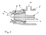
- the Moineau pump comprises an inner element 2 and an outer element 4. Both are of conical shape, i.e. the inner element 2 has a conical outer shape and the cavity of the outer element 4 has a conical inner shape so that the inner element 2 fits into the outer element 4.
- the outer surface of the inner element 2 and the inner surface of the outer surface 4 have a helical shape with the helical structure of the outer element 4 having one thread more than the helical structure of the inner element 2.
- Both, inner element 2 and outer element 4 are arranged in a pump housing or casing 6.
- the inner element 2 is fixed on a motor shaft (not shown).
- the motor shaft extends along the longitudinal axis X 1 of the inner element 2.
- This motor shaft is driving the inner element 2 so that it is rotating about its longitudinal axis X 1 forming a first rotation axis X 1 .
- the outer element 4 is mounted in radial bearings 8 inside the casing 6.
- the outer element 4 is freely rotatable about its longitudinal axis X 2 forming a second rotation axis. Further, the outer element 4 is movable in axial direction along the axis X 2 inside the casing 6 and the bearings 8.
- the radial bearings 8 are fixed in the casing 6.
- the pump according to Fig. 1 has its pressure side on the side of inner element 2 and outer element 4 having the smaller diameter, the suction side is on the opposite side having the larger diameter.
- the fluid to be pumped enters the pump housing 6 through inlet 10 and is pumped to outlet 12. Therefore, the pump pressure on the outlet side 12 acts in direction of arrows A parallel to the longitudinal axis X 2 against the outer element 4 so that the outer element 4 is pressed against the outside of the inner element 2. This allows that with increasing pump pressure the pressing force between outer and inner element increases. When the pump is not working this force can be reduced to zero so that a low starting torque can be achieved.
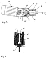
- a second different embodiment is shown in fig. 2 .
- the embodiment according to Fig. 2 has an outer element 4' and an inner element 2' which are arranged and designed as explained above in connection with the first embodiment.
- the difference between the first and the second embodiment is that according to the second embodiment the outer element 4' is driven by the motor (not shown in fig. 2 ).
- the outer element 4' drives the inner element 2'. Therefore, the inner element 2' is mounted for rotation on bearings 14 arranged on a fixed inlet tube 16.
- the bearings 14 are radial bearings so that the inner element 2' is movable in axial direction parallel to the longitudinal axis of the inlet tube 16. Further, the inner element 2' is rotatable about this longitudinal axis.
- the outer element 4' rotates about a second longitudinal axis inclined to the longitudinal axis of the inlet tube 16 corresponding to the embodiment of Fig.1 .
- the outer element 4' is connected with the motor shaft and mounted in axial and radial bearings.
- the pump is arranged in pump housing or casing 6' having the inlet tube 16 and an outlet 18.
- the driving shaft of the outer element 4 is passed though a shaft seal 20 which prevents leakage in the motor and of the pump.
- Fig. 3 shows an embodiment corresponding to the embodiment according to Fig.1 . It can be seen that the rotation axis X 1 of the motor and the inner element 2 is inclined to the longitudinal and rotation X 2 of the outer element 4.
- the motor 24 is connected to the pump casing 6 and the motor shaft 26 is passed through a seal 28.
- the inner element 2 drives the outer element 4.
- the speed of the outer element is determined by the product of the speed of the inner element 2 and the of teeth or threads of said inner element and said outer element. That means if said inner element has a circular cross section as shown in Fig. 6 (having one tooth or thread) then said outer element has a cross section as elongated circle as shown Fig. 7 (two threads or teeth) and the rotational speed of the outer element 4 will be the half of the rotational speed of the inner element 2. On the other hand if said inner element has nine teeth or threads then said outer element has ten teeth or threads as shown in the cross sectional view of Fig. 8 and the speed of said outer element will be nine tenth of the speed of said inner element.
- the motor 24 may be an electro motor AC, DC, PM or hydraulic motor, combustion engine or similar.
- Fig. 4 shows a further possibility to arrange the outer element 4" and the inner element 2".
- the pressure side or outlet 30 of the pump is arranged on the small diameter end of the conical inner element 2" and the conical outer element 4".
- the inner element 2" has an internal channel 32 extending along its longitudinal axis from the pressure side 30 to the opposite side. On the opposite side this channel 32 is broadend so that a surface 34 is formed which is directed opposite to the pressure side 30.
- the outlet pressure produced by the pump acts on the surface 34 and presses the inner element 2" against the outer element 4" with increasing pressure as explained above.
- a progressive cavity pump (PCP) or Moineau pump has two parts (inner part 2 and outer part 4) rotating relative to each other and moving in an eccentric track relative to each other. According to the present invention this is achieved by the inclined rotation axes X 1 and X 2 of the inner and outer part.
- the shapes in cross section, in particular along its spherical cross section with the intersection point of both rotation axes forming the centre point of this sphere can be made of pieces of hypocycloids connected with epicycloids as shown in Fig. 5 . Alternatively it can be occurred with constant distance or offset to hypocycloids.
- the cross section In the axial direction the cross section is rotated around the longitudinal axis so that it forms at least one thread or tooth on the outside of the inner part and at least two threads or teeth on the inside of the outer part 4.
- the number of threads or teeth of the inner part is (n+1)/n times the number of threads or teeth of the outer part.
- the centre of the inner element 2 is offset relative to the centre of the outer element 4 and moving in a circle with a radius e (eccentricity), In the present case because of the conical shape the eccentricity is increasing from one longitudinal end of the pump to the other longitudinal end.
Landscapes
- Engineering & Computer Science (AREA)
- Mechanical Engineering (AREA)
- General Engineering & Computer Science (AREA)
- Rotary Pumps (AREA)
- Structures Of Non-Positive Displacement Pumps (AREA)
- Nitrogen Condensed Heterocyclic Rings (AREA)
- Saccharide Compounds (AREA)
- Lubrication Of Internal Combustion Engines (AREA)
Claims (8)
- Pompe Moineau comportant un élément de pompage hélicoïdal extérieur (4; 4'), et un élément de pompage hélicoïdal intérieur (2 ; 2') agencé à l'intérieur de l'élément extérieur (4 ; 4'), dans laquelle l'intérieur de l'élément extérieur (4, 4') et de l'élément intérieur (2 ; 2') sont de forme conique,
l'élément intérieur (2; 2') peut tourner autour de son axe longitudinal (X1) qui forme un premier axe de rotation fixe (X1), et l'élément extérieur (4 ; 4') peut tourner autour de son axe longitudinal (X2) qui forme un second axe de rotation fixe (X2),
et dans laquelle le premier axe de rotation (X1) et le second axe de rotation (X2) sont inclinés l'un par rapport à l'autre, et l'élément intérieur (2 ; 2') est entraîné par l'élément extérieur (4 ; 4') ou l'élément extérieur (4, 4') est entraîné par l'élément intérieur (2:2'),
caractérisée en ce que ledit élément intérieur (2 ; 2') ou ledit élément extérieur (4 ; 4') est agencé de telle manière que ledit élément intérieur (2 ; 2') ou ledit élément extérieur (4 ; 4') soit mobile dans la direction axiale et en ce qu'il est prévu sur l'élément mobile dans la direction axiale une surface sur laquelle la pression produite par la pompe agit de telle manière que l'action de la pression ait pour résultat une force axiale qui presse l'élément intérieur (2 ; 2') et l'élément extérieur (4 ; 4') l'un contre l'autre. - Pompe Moineau selon la revendication 1, caractérisée en ce qu'au moins une partie dudit élément intérieur (2 ; 2') et/ou dudit élément extérieur (4 ; 4') est faite d'au moins une matière rigide
- Pompe Moineau selon la revendication 2, caractérisée en ce que ledit élément intérieur (2 ; 2') et/ou ledit élément extérieur (4 ; 4') est ou sont fait(s) d'une matière céramique.
- Pompe Moineau selon l'une des revendications précédentes, caractérisée en ce que, soit ledit élément intérieur (2 ; 2'), soit ledit élément extérieur (4 ; 4') est entraîné par un moyen d'entraînement, de préférence par un moteur (24).
- Pompe Moineau selon la revendication 4, caractérisée en ce que, soit ledit élément intérieur (2 ; 2'), soit ledit élément extérieur (4 ; 4') est entraîné par un moteur (24), l'axe de rotation dudit moteur s'étendant dans la même direction que ledit axe de rotation dudit élément entraîné par ledit moteur (24).
- Pompe Moineau selon l'une des revendications précédentes, caractérisée en ce que ledit élément extérieur (4 ; 4') a une dent de plus que ledit élément intérieur (2 ; 2').
- Pompe Moineau selon l'une des revendications précédentes, caractérisée en ce que la matière ou le fluide qui est pompé circule axialement à travers ladite pompe, sensiblement selon une ligne droite.
- Pompe Moineau selon l'une des revendications précédentes, caractérisée en ce que la pompe comprend un corps (6 ; 6') ayant des orifices d'entrée (10; 16) et de sortie (12 ; 18) et ledit élément intérieur (2 ; 2') et ledit élément extérieur (4 ; 4') sont agencés dans ledit corps (6 ; 6').
Applications Claiming Priority (2)
| Application Number | Priority Date | Filing Date | Title |
|---|---|---|---|
| DKPA200600885 | 2006-06-30 | ||
| PCT/EP2007/005787 WO2008000505A1 (fr) | 2006-06-30 | 2007-06-29 | pompe MOINEAU |
Publications (2)
| Publication Number | Publication Date |
|---|---|
| EP2035708A1 EP2035708A1 (fr) | 2009-03-18 |
| EP2035708B1 true EP2035708B1 (fr) | 2011-05-04 |
Family
ID=38520133
Family Applications (1)
| Application Number | Title | Priority Date | Filing Date |
|---|---|---|---|
| EP07764954A Not-in-force EP2035708B1 (fr) | 2006-06-30 | 2007-06-29 | Pompe moineau |
Country Status (5)
| Country | Link |
|---|---|
| EP (1) | EP2035708B1 (fr) |
| CN (1) | CN101473139B (fr) |
| AT (1) | ATE508279T1 (fr) |
| DE (1) | DE602007014364D1 (fr) |
| WO (1) | WO2008000505A1 (fr) |
Families Citing this family (8)
| Publication number | Priority date | Publication date | Assignee | Title |
|---|---|---|---|---|
| DE202009002823U1 (de) | 2009-03-02 | 2009-07-30 | Daunheimer, Ralf | Exzenterschneckenpumpe |
| CN103775334B (zh) * | 2014-02-13 | 2016-01-13 | 北京工业大学 | 一种锥螺杆-衬套副 |
| EP3108142B1 (fr) | 2014-02-18 | 2017-11-15 | Vert Rotors UK Limited | Machine volumétrique rotative |
| JP5802914B1 (ja) * | 2014-11-14 | 2015-11-04 | 兵神装備株式会社 | 流動体搬送装置 |
| US10174973B2 (en) | 2015-08-27 | 2019-01-08 | Vert Rotors Uk Limited | Miniature low-vibration active cooling system with conical rotary compressor |
| US9776739B2 (en) | 2015-08-27 | 2017-10-03 | Vert Rotors Uk Limited | Miniature low-vibration active cooling system with conical rotary compressor |
| DE102017210767B4 (de) * | 2017-06-27 | 2019-10-17 | Continental Automotive Gmbh | Schraubenspindelpumpe, Kraftstoffförderaggregat und Kraftstofffördereinheit |
| BE1025570B1 (nl) * | 2017-09-21 | 2019-04-17 | Atlas Copco Airpower Naamloze Vennootschap | Cilindrisch symmetrische volumetrische machine |
Family Cites Families (4)
| Publication number | Priority date | Publication date | Assignee | Title |
|---|---|---|---|---|
| USRE21374E (en) * | 1940-02-27 | Gear mechanism | ||
| DE2632716A1 (de) * | 1976-07-21 | 1978-01-26 | Martin Theodor Melchior | Fluessigkeitspumpe, insbesondere fuer gips-anwurfgeraete |
| US5759019A (en) * | 1994-02-14 | 1998-06-02 | Steven M. Wood | Progressive cavity pumps using composite materials |
| US6361292B1 (en) * | 2000-04-12 | 2002-03-26 | Sheldon S. L. Chang | Linear flow blood pump |
-
2007
- 2007-06-29 AT AT07764954T patent/ATE508279T1/de not_active IP Right Cessation
- 2007-06-29 DE DE602007014364T patent/DE602007014364D1/de active Active
- 2007-06-29 EP EP07764954A patent/EP2035708B1/fr not_active Not-in-force
- 2007-06-29 WO PCT/EP2007/005787 patent/WO2008000505A1/fr not_active Ceased
- 2007-06-29 CN CN2007800230444A patent/CN101473139B/zh not_active Expired - Fee Related
Also Published As
| Publication number | Publication date |
|---|---|
| ATE508279T1 (de) | 2011-05-15 |
| DE602007014364D1 (de) | 2011-06-16 |
| WO2008000505A1 (fr) | 2008-01-03 |
| CN101473139B (zh) | 2013-08-28 |
| CN101473139A (zh) | 2009-07-01 |
| EP2035708A1 (fr) | 2009-03-18 |
Similar Documents
| Publication | Publication Date | Title |
|---|---|---|
| EP2035708B1 (fr) | Pompe moineau | |
| EP1988288B1 (fr) | Pompe Moineau | |
| US9920755B2 (en) | Pump integrated with two independently driven prime movers | |
| US10962004B2 (en) | Synchronized conical screw compressor or pump | |
| EP2610493B1 (fr) | Structure d'étanchéité de stator pour pompe à vis excentrique à arbre unique | |
| US5056994A (en) | Hydrostatic rotary piston machine having interacting tooth systems | |
| CN101835986B (zh) | 用于制动系统的内啮合齿轮泵 | |
| CA3112348A1 (fr) | Machines rotatives trochoidales helicoides et trochoidales decalees | |
| EP2035709B1 (fr) | Pompe de type moineau | |
| US8496456B2 (en) | Progressive cavity pump including inner and outer rotors and a wheel gear maintaining an interrelated speed ratio | |
| CN100476210C (zh) | 内啮合齿轮泵或马达 | |
| CN104246130B (zh) | 作为用于流体的泵、压缩机或马达的旋转活塞机 | |
| CN107654260B (zh) | 齿轮流体机 | |
| RU2283441C1 (ru) | Трохоидная роторная машина (варианты) | |
| US6524087B1 (en) | Hydrostatic planetary rotation machine having an orbiting rotary valve | |
| HK1245373B (en) | Rotary positive-displacement machine | |
| RU2319014C1 (ru) | Роторная объемная машина (варианты) |
Legal Events
| Date | Code | Title | Description |
|---|---|---|---|
| PUAI | Public reference made under article 153(3) epc to a published international application that has entered the european phase |
Free format text: ORIGINAL CODE: 0009012 |
|
| 17P | Request for examination filed |
Effective date: 20081119 |
|
| AK | Designated contracting states |
Kind code of ref document: A1 Designated state(s): AT BE BG CH CY CZ DE DK EE ES FI FR GB GR HU IE IS IT LI LT LU LV MC MT NL PL PT RO SE SI SK TR |
|
| AX | Request for extension of the european patent |
Extension state: AL BA HR MK RS |
|
| GRAP | Despatch of communication of intention to grant a patent |
Free format text: ORIGINAL CODE: EPIDOSNIGR1 |
|
| GRAS | Grant fee paid |
Free format text: ORIGINAL CODE: EPIDOSNIGR3 |
|
| GRAA | (expected) grant |
Free format text: ORIGINAL CODE: 0009210 |
|
| AK | Designated contracting states |
Kind code of ref document: B1 Designated state(s): AT BE BG CH CY CZ DE DK EE ES FI FR GB GR HU IE IS IT LI LT LU LV MC MT NL PL PT RO SE SI SK TR |
|
| REG | Reference to a national code |
Ref country code: GB Ref legal event code: FG4D |
|
| REG | Reference to a national code |
Ref country code: CH Ref legal event code: EP |
|
| REG | Reference to a national code |
Ref country code: IE Ref legal event code: FG4D |
|
| REF | Corresponds to: |
Ref document number: 602007014364 Country of ref document: DE Date of ref document: 20110616 Kind code of ref document: P |
|
| REG | Reference to a national code |
Ref country code: DE Ref legal event code: R096 Ref document number: 602007014364 Country of ref document: DE Effective date: 20110616 |
|
| REG | Reference to a national code |
Ref country code: NL Ref legal event code: VDEP Effective date: 20110504 |
|
| PG25 | Lapsed in a contracting state [announced via postgrant information from national office to epo] |
Ref country code: SE Free format text: LAPSE BECAUSE OF FAILURE TO SUBMIT A TRANSLATION OF THE DESCRIPTION OR TO PAY THE FEE WITHIN THE PRESCRIBED TIME-LIMIT Effective date: 20110504 Ref country code: LT Free format text: LAPSE BECAUSE OF FAILURE TO SUBMIT A TRANSLATION OF THE DESCRIPTION OR TO PAY THE FEE WITHIN THE PRESCRIBED TIME-LIMIT Effective date: 20110504 Ref country code: PT Free format text: LAPSE BECAUSE OF FAILURE TO SUBMIT A TRANSLATION OF THE DESCRIPTION OR TO PAY THE FEE WITHIN THE PRESCRIBED TIME-LIMIT Effective date: 20110905 |
|
| PG25 | Lapsed in a contracting state [announced via postgrant information from national office to epo] |
Ref country code: IS Free format text: LAPSE BECAUSE OF FAILURE TO SUBMIT A TRANSLATION OF THE DESCRIPTION OR TO PAY THE FEE WITHIN THE PRESCRIBED TIME-LIMIT Effective date: 20110904 Ref country code: LV Free format text: LAPSE BECAUSE OF FAILURE TO SUBMIT A TRANSLATION OF THE DESCRIPTION OR TO PAY THE FEE WITHIN THE PRESCRIBED TIME-LIMIT Effective date: 20110504 Ref country code: GR Free format text: LAPSE BECAUSE OF FAILURE TO SUBMIT A TRANSLATION OF THE DESCRIPTION OR TO PAY THE FEE WITHIN THE PRESCRIBED TIME-LIMIT Effective date: 20110805 Ref country code: CY Free format text: LAPSE BECAUSE OF FAILURE TO SUBMIT A TRANSLATION OF THE DESCRIPTION OR TO PAY THE FEE WITHIN THE PRESCRIBED TIME-LIMIT Effective date: 20110504 Ref country code: FI Free format text: LAPSE BECAUSE OF FAILURE TO SUBMIT A TRANSLATION OF THE DESCRIPTION OR TO PAY THE FEE WITHIN THE PRESCRIBED TIME-LIMIT Effective date: 20110504 Ref country code: SI Free format text: LAPSE BECAUSE OF FAILURE TO SUBMIT A TRANSLATION OF THE DESCRIPTION OR TO PAY THE FEE WITHIN THE PRESCRIBED TIME-LIMIT Effective date: 20110504 Ref country code: AT Free format text: LAPSE BECAUSE OF FAILURE TO SUBMIT A TRANSLATION OF THE DESCRIPTION OR TO PAY THE FEE WITHIN THE PRESCRIBED TIME-LIMIT Effective date: 20110504 Ref country code: ES Free format text: LAPSE BECAUSE OF FAILURE TO SUBMIT A TRANSLATION OF THE DESCRIPTION OR TO PAY THE FEE WITHIN THE PRESCRIBED TIME-LIMIT Effective date: 20110815 Ref country code: BE Free format text: LAPSE BECAUSE OF FAILURE TO SUBMIT A TRANSLATION OF THE DESCRIPTION OR TO PAY THE FEE WITHIN THE PRESCRIBED TIME-LIMIT Effective date: 20110504 |
|
| PG25 | Lapsed in a contracting state [announced via postgrant information from national office to epo] |
Ref country code: NL Free format text: LAPSE BECAUSE OF FAILURE TO SUBMIT A TRANSLATION OF THE DESCRIPTION OR TO PAY THE FEE WITHIN THE PRESCRIBED TIME-LIMIT Effective date: 20110504 Ref country code: MT Free format text: LAPSE BECAUSE OF FAILURE TO SUBMIT A TRANSLATION OF THE DESCRIPTION OR TO PAY THE FEE WITHIN THE PRESCRIBED TIME-LIMIT Effective date: 20110504 |
|
| PG25 | Lapsed in a contracting state [announced via postgrant information from national office to epo] |
Ref country code: EE Free format text: LAPSE BECAUSE OF FAILURE TO SUBMIT A TRANSLATION OF THE DESCRIPTION OR TO PAY THE FEE WITHIN THE PRESCRIBED TIME-LIMIT Effective date: 20110504 Ref country code: CZ Free format text: LAPSE BECAUSE OF FAILURE TO SUBMIT A TRANSLATION OF THE DESCRIPTION OR TO PAY THE FEE WITHIN THE PRESCRIBED TIME-LIMIT Effective date: 20110504 |
|
| REG | Reference to a national code |
Ref country code: CH Ref legal event code: PL |
|
| PG25 | Lapsed in a contracting state [announced via postgrant information from national office to epo] |
Ref country code: DK Free format text: LAPSE BECAUSE OF FAILURE TO SUBMIT A TRANSLATION OF THE DESCRIPTION OR TO PAY THE FEE WITHIN THE PRESCRIBED TIME-LIMIT Effective date: 20110504 Ref country code: RO Free format text: LAPSE BECAUSE OF FAILURE TO SUBMIT A TRANSLATION OF THE DESCRIPTION OR TO PAY THE FEE WITHIN THE PRESCRIBED TIME-LIMIT Effective date: 20110504 Ref country code: SK Free format text: LAPSE BECAUSE OF FAILURE TO SUBMIT A TRANSLATION OF THE DESCRIPTION OR TO PAY THE FEE WITHIN THE PRESCRIBED TIME-LIMIT Effective date: 20110504 Ref country code: PL Free format text: LAPSE BECAUSE OF FAILURE TO SUBMIT A TRANSLATION OF THE DESCRIPTION OR TO PAY THE FEE WITHIN THE PRESCRIBED TIME-LIMIT Effective date: 20110504 |
|
| PLBE | No opposition filed within time limit |
Free format text: ORIGINAL CODE: 0009261 |
|
| STAA | Information on the status of an ep patent application or granted ep patent |
Free format text: STATUS: NO OPPOSITION FILED WITHIN TIME LIMIT |
|
| REG | Reference to a national code |
Ref country code: IE Ref legal event code: MM4A |
|
| 26N | No opposition filed |
Effective date: 20120207 |
|
| PG25 | Lapsed in a contracting state [announced via postgrant information from national office to epo] |
Ref country code: IE Free format text: LAPSE BECAUSE OF NON-PAYMENT OF DUE FEES Effective date: 20110629 Ref country code: CH Free format text: LAPSE BECAUSE OF NON-PAYMENT OF DUE FEES Effective date: 20110630 Ref country code: LI Free format text: LAPSE BECAUSE OF NON-PAYMENT OF DUE FEES Effective date: 20110630 |
|
| REG | Reference to a national code |
Ref country code: DE Ref legal event code: R097 Ref document number: 602007014364 Country of ref document: DE Effective date: 20120207 |
|
| PG25 | Lapsed in a contracting state [announced via postgrant information from national office to epo] |
Ref country code: MC Free format text: LAPSE BECAUSE OF NON-PAYMENT OF DUE FEES Effective date: 20110630 |
|
| PG25 | Lapsed in a contracting state [announced via postgrant information from national office to epo] |
Ref country code: LU Free format text: LAPSE BECAUSE OF NON-PAYMENT OF DUE FEES Effective date: 20110629 |
|
| PG25 | Lapsed in a contracting state [announced via postgrant information from national office to epo] |
Ref country code: BG Free format text: LAPSE BECAUSE OF FAILURE TO SUBMIT A TRANSLATION OF THE DESCRIPTION OR TO PAY THE FEE WITHIN THE PRESCRIBED TIME-LIMIT Effective date: 20110804 |
|
| PG25 | Lapsed in a contracting state [announced via postgrant information from national office to epo] |
Ref country code: TR Free format text: LAPSE BECAUSE OF FAILURE TO SUBMIT A TRANSLATION OF THE DESCRIPTION OR TO PAY THE FEE WITHIN THE PRESCRIBED TIME-LIMIT Effective date: 20110504 |
|
| PG25 | Lapsed in a contracting state [announced via postgrant information from national office to epo] |
Ref country code: HU Free format text: LAPSE BECAUSE OF FAILURE TO SUBMIT A TRANSLATION OF THE DESCRIPTION OR TO PAY THE FEE WITHIN THE PRESCRIBED TIME-LIMIT Effective date: 20110504 |
|
| REG | Reference to a national code |
Ref country code: FR Ref legal event code: PLFP Year of fee payment: 10 |
|
| REG | Reference to a national code |
Ref country code: FR Ref legal event code: PLFP Year of fee payment: 11 |
|
| REG | Reference to a national code |
Ref country code: FR Ref legal event code: PLFP Year of fee payment: 12 |
|
| PGFP | Annual fee paid to national office [announced via postgrant information from national office to epo] |
Ref country code: GB Payment date: 20220623 Year of fee payment: 16 |
|
| PGFP | Annual fee paid to national office [announced via postgrant information from national office to epo] |
Ref country code: FR Payment date: 20220622 Year of fee payment: 16 |
|
| REG | Reference to a national code |
Ref country code: DE Ref legal event code: R082 Ref document number: 602007014364 Country of ref document: DE |
|
| PGFP | Annual fee paid to national office [announced via postgrant information from national office to epo] |
Ref country code: IT Payment date: 20220630 Year of fee payment: 16 Ref country code: DE Payment date: 20220624 Year of fee payment: 16 |
|
| REG | Reference to a national code |
Ref country code: DE Ref legal event code: R119 Ref document number: 602007014364 Country of ref document: DE |
|
| GBPC | Gb: european patent ceased through non-payment of renewal fee |
Effective date: 20230629 |
|
| PG25 | Lapsed in a contracting state [announced via postgrant information from national office to epo] |
Ref country code: DE Free format text: LAPSE BECAUSE OF NON-PAYMENT OF DUE FEES Effective date: 20240103 Ref country code: GB Free format text: LAPSE BECAUSE OF NON-PAYMENT OF DUE FEES Effective date: 20230629 |
|
| PG25 | Lapsed in a contracting state [announced via postgrant information from national office to epo] |
Ref country code: FR Free format text: LAPSE BECAUSE OF NON-PAYMENT OF DUE FEES Effective date: 20230630 |
|
| PG25 | Lapsed in a contracting state [announced via postgrant information from national office to epo] |
Ref country code: IT Free format text: LAPSE BECAUSE OF NON-PAYMENT OF DUE FEES Effective date: 20230629 |