EP2035711B1 - Merhstufige verdichtervorrichtung - Google Patents
Merhstufige verdichtervorrichtung Download PDFInfo
- Publication number
- EP2035711B1 EP2035711B1 EP07719217.7A EP07719217A EP2035711B1 EP 2035711 B1 EP2035711 B1 EP 2035711B1 EP 07719217 A EP07719217 A EP 07719217A EP 2035711 B1 EP2035711 B1 EP 2035711B1
- Authority
- EP
- European Patent Office
- Prior art keywords
- compressor
- expander
- compressor device
- compressor element
- foregoing
- Prior art date
- Legal status (The legal status is an assumption and is not a legal conclusion. Google has not performed a legal analysis and makes no representation as to the accuracy of the status listed.)
- Active
Links
Images


Classifications
-
- F—MECHANICAL ENGINEERING; LIGHTING; HEATING; WEAPONS; BLASTING
- F04—POSITIVE - DISPLACEMENT MACHINES FOR LIQUIDS; PUMPS FOR LIQUIDS OR ELASTIC FLUIDS
- F04D—NON-POSITIVE-DISPLACEMENT PUMPS
- F04D25/00—Pumping installations or systems
- F04D25/02—Units comprising pumps and their driving means
-
- F—MECHANICAL ENGINEERING; LIGHTING; HEATING; WEAPONS; BLASTING
- F04—POSITIVE - DISPLACEMENT MACHINES FOR LIQUIDS; PUMPS FOR LIQUIDS OR ELASTIC FLUIDS
- F04D—NON-POSITIVE-DISPLACEMENT PUMPS
- F04D25/00—Pumping installations or systems
- F04D25/02—Units comprising pumps and their driving means
- F04D25/024—Units comprising pumps and their driving means the driving means being assisted by a power recovery turbine
-
- F—MECHANICAL ENGINEERING; LIGHTING; HEATING; WEAPONS; BLASTING
- F01—MACHINES OR ENGINES IN GENERAL; ENGINE PLANTS IN GENERAL; STEAM ENGINES
- F01K—STEAM ENGINE PLANTS; STEAM ACCUMULATORS; ENGINE PLANTS NOT OTHERWISE PROVIDED FOR; ENGINES USING SPECIAL WORKING FLUIDS OR CYCLES
- F01K23/00—Plants characterised by more than one engine delivering power external to the plant, the engines being driven by different fluids
-
- F—MECHANICAL ENGINEERING; LIGHTING; HEATING; WEAPONS; BLASTING
- F01—MACHINES OR ENGINES IN GENERAL; ENGINE PLANTS IN GENERAL; STEAM ENGINES
- F01K—STEAM ENGINE PLANTS; STEAM ACCUMULATORS; ENGINE PLANTS NOT OTHERWISE PROVIDED FOR; ENGINES USING SPECIAL WORKING FLUIDS OR CYCLES
- F01K3/00—Plants characterised by the use of steam or heat accumulators, or intermediate steam heaters, therein
- F01K3/006—Accumulators and steam compressors
-
- F—MECHANICAL ENGINEERING; LIGHTING; HEATING; WEAPONS; BLASTING
- F04—POSITIVE - DISPLACEMENT MACHINES FOR LIQUIDS; PUMPS FOR LIQUIDS OR ELASTIC FLUIDS
- F04B—POSITIVE-DISPLACEMENT MACHINES FOR LIQUIDS; PUMPS
- F04B35/00—Piston pumps specially adapted for elastic fluids and characterised by the driving means to their working members, or by combination with, or adaptation to, specific driving engines or motors, not otherwise provided for
-
- F—MECHANICAL ENGINEERING; LIGHTING; HEATING; WEAPONS; BLASTING
- F04—POSITIVE - DISPLACEMENT MACHINES FOR LIQUIDS; PUMPS FOR LIQUIDS OR ELASTIC FLUIDS
- F04D—NON-POSITIVE-DISPLACEMENT PUMPS
- F04D19/00—Axial-flow pumps
- F04D19/02—Multi-stage pumps
Definitions
- This invention relates to an improved compressor device.
- a known solution for limiting the heat generated during the compression of the gas is to inject a liquid coolant with a high heat capacity into the compressor element of the compressor device. For example, this is the case with so-called oil-injected and water-injected screw compressors.
- Another known solution for seeking isothermal compression is to have the compression take place in several steps with constantly increasing pressure, in successive, serially connected compressor elements, and to cool the compressed gas using an intercooler between successive steps.
- An alternative is to recover the latent heat from the compressed gas for other useful purposes or applications, for example for use in a heating or similar installation.
- This mechanical energy is used, for example, to drive an electric generator, or is used to reduce the load on the motor which is used to drive the compressor device, so that a smaller motor can be used.
- the turbine is directly mechanically linked via its axle to the drive axle of said motor or of one or more compressor elements of the compressor device. Because the compressor elements and turbine are mechanically linked, the choice of these components is restricted, as a result of which these components cannot each be optimised in its own right.
- EP 1.389.672 describes a method and device to compress a stream of gas in at least a first compression stage and consecutively cool it by indirect heat exchange with an evaporating refrigerant in a first evaporator.
- the refrigerant is circulated in a refrigeration cycle.
- the expansion of the refrigerant in the refrigeration cycle is done while performing work.
- US 5.413.467 describes a device for producing compressed air arranged to suction air from the atmosphere and increase the pressure of the suctioned air by a turbo supercharger, to cool the air at high temperature by passing the air through an intercooler an to compress the air to a required pressure by an oil-free screw compressor.
- the present invention relates to a compressor device with improved efficiency and more options for the optimisation of each individual component and hence too of the compressor device as a whole.
- the invention relates to an improved multi-stage compressor device for compressing gas according to claim 1. More particular the invention relates to an improved multi-stage compressor device, which compressor device mainly consists of at least two compressor elements placed in series one after the other, at least one of which forms a high-pressure compressor element that is driven by a motor and is of the screw type, while at least one other compressor element forms a low-pressure compressor element that is of the centrifugal type and is driven separately, in other words without any mechanical link with said motor, by means of an expander.
- the improved multi-stage compressor device is characterized
- the compressed gas's heat is thus used to drive a component of the compressor device, using an efficient power cycle, preferably functioning according to the so-called Rankine cycle process, in which the hot gases, from the high-pressure compressor element function as a heat source.
- the compressor element which is driven separately by the expander is decoupled from the compressor element which is driven by the motor, the compressor element which is driven by the expander can be driven at a different speed from the compressor element which is driven by the motor.
- a compressor element can be chosen which can be driven directly at a high speed by the expander without the intervention of a transmission box or some similar element.
- the medium in the closed power cycle is pumped around by means of a pump, successively through: a heater which is made up of at least one heat exchanger through which at least part of the compressed gas flows; said expander which is connected with a said compressor element; and a condenser.
- the medium is evaporated in the heater into a gas with high energy which drives the expander, for example a turbine, and hence also the compressor element which is linked to it, during which the gas in the expander undergoes expansion, after which the gaseous medium which leaves the expander is liquefied again at low pressure in the condenser, in order to then be sent by the pump again at an increased pressure through the heater and thus start a new cycle in the closed power cycle.
- a gas with high energy which drives the expander for example a turbine, and hence also the compressor element which is linked to it, during which the gas in the expander undergoes expansion, after which the gaseous medium which leaves the expander is liquefied again at low pressure in the condenser, in order to then be sent by the pump again at an increased pressure through the heater and thus start a new cycle in the closed power cycle.
- the expander for example a turbine
- the expander can be driven at very high speeds, which for example makes it possible to use a turbocompressor in a favourable manner as a compressor element which is driven by the expander.
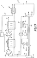
- the compressor device 1 in figure 1 mainly consists of two compressor elements: a first compressor element 2 with an inlet 3 and an outlet 4 and a second compressor element 5, likewise with an inlet 6 and an outlet 7.
- the compressor elements 2 and 5 are serially connected by means of a line 8 which connects the outlet 4 of the first compressor element 2 with the inlet 6 of the second compressor element 5.
- the first compressor element 2 is upstream of the second compressor element 5, in terms of the direction of flow of the compressed gas, and works at lower pressures than the second compressor element 5, as a result of which these compressor elements 2 and 5 are also occasionally referred to as a low-pressure compressor element 2 and a high-pressure compressor element 5, which thus does not mean that the low pressure element must necessarily work at a low pressure.
- the high-pressure compressor element 5 is driven by a motor 9, and in this case is connected via a pressure line 10 with a mains network 11 or similar.
- the low-pressure compressor element 2 is in this case a component of the compressor device 1 which according to the invention is driven by a closed power cycle 12 which functions according to the principle of a Rankine cycle process.
- the power cycle 12 consists in the depicted example of a closed loop 13 in which a medium such as pentane, water, CO 2 or any other suitable medium is pumped around in a particular flow direction 14, for example by means of a pump 15 which is driven by a motor 16.
- a medium such as pentane, water, CO 2 or any other suitable medium
- the loop 13 contains successively, in the direction of flow 14 of the medium, a heater in the form of a heat exchanger 17, an expander 18, in this case in the form of a turbine 18, and a condenser 19.
- the turbine 18 is fitted with an inlet 20 and an outlet 21 for the medium and is connected by means of transmission 22 with the incoming axle of the low-pressure compressor element 2, the foregoing points ensuring that the low-pressure compressor element 2 is driven separately from the high-pressure compressor element 5 without any mechanical linkage between the two compressor elements 2 and 5 or the motor 9 of the compressor element 5.
- both the low-pressure compressor element 2 and the turbine 18 are of the turbo type, as a result of which the transmission 22 can be a direct link by means of an axle.
- the possibility is not excluded that other types of compressor element or expander, and more particularly turbines, may be used, such as of the spiral type, of the screw type, and so on.
- the condenser 19 is a heat exchanger for cooling the medium which flows through it, and in this case takes the form of air cooling which is provided by an external fan 23 with drive 24.
- the working of the improved compressor device 1 is simple, and proceeds as follows.
- the high-pressure compressor element 5 is driven by the motor 9 and delivers a particular flow of compressed gas which is delivered via the pressure line 10 and the heat exchanger 17 of the heater to the mains network 11.
- the pump 15 is also driven by means of the motor 16 so as to pump the medium round the loop 13 in the direction 14, in the process of which the medium is brought by the pump 15 to an increased pressure of, for example, 10 bar.
- the medium flows in liquid form into the heat exchanger 17 of the heater, and is evaporated to a gaseous phase by the heat transfer in the heater 17.
- the gas which is formed flows into the turbine 18 at a relatively high pressure and temperature.
- the gaseous phase of the medium undergoes expansion, as a result of which the turbine 18 is driven at a high speed, as a result of which this turbine 18 will in turn drive the low-pressure compressor element 2.
- the gas to be compressed is taken in via the inlet 3 and compressed in the low-pressure compressor element 2 to a certain intermediate pressure.
- the medium leaves the turbine 18 at a considerably reduced pressure and temperature and is cooled in the condenser 19 in order to condense and reliquefy, as a result of which the reliquefied medium can be taken up and pumped around again by the pump 15 for the next operating cycle.
- the various components can be adapted for the best result.
- pentane another medium such as water or CO 2 may be used if necessary, preferably a medium with a relatively low boiling point which is lower than 150 degrees Celsius.
- compressor for the compressor, of course, all types of compressor may be used as a high-pressure compressor element, such as screw compressors, oil-free compressors and so on.
- the turbine 18 and the low-pressure compressor element 2 also need not necessarily be of the turbo type, but can for example also be of the screw type or of the spiral type, and they may be all of the same type or each of a different type.
- the volume of the compressor element 2 used may be much smaller than in the conventionally used compressor elements which need to be driven at a low speed, so that a compressor device according to the invention with such a compressor element 2 of the turbo type also takes less space than known compressor devices.
- such a compressor device In combination with a motor 9 of the thermal type, such a compressor device is therefore highly suitable for a portable version of the compressor type.
- the heater 17 and the expander 18 are preferably high-efficiency components which can operated with a small temperature difference.
- the medium in the power cycle 12 may circulate as a result of the thermodynamic working of the cycle process, without a pump 15 being needed for this.
- FIG 2 an improved compressor device according to the invention is shown, which differs from the embodiment in figure 1 in that the heater in the closed power cycle 12 contains an additional heat exchanger 25 which is included upstream of the heat exchanger 17 in the power cycle 12, and in that the motor 9 to drive the high-pressure compressor element 5 is a thermal motor whose exhaust gases are conveyed via an outlet line 26 through an additional heat exchanger 27, which is also included as a heater in the loop 13 for heating the medium in this power cycle 12.
- This heat exchanger 25 takes the form of an intercooler which is included in the line 8 which connects the low-pressure compressor element 2 with the high-pressure compressor element 5.
- this intercooler 25 By the use of this intercooler 25 the gas which is compressed in the high-pressure compressor element 5 is pre-cooled, which has a positive effect on the efficiency of the high-pressure compressor element 5 and moreover provides an additional heat source which can supply energy to the medium in the power cycle 12.
- the heater can consist of just one of the heat exchangers 17, 25 and 27.
- the heat exchanger 27 may be included upstream or downstream of the heat exchanger 17 in the loop 13.
- FIG 3 a variant is shown of such a compressor device according to the invention, in which the heat exchanger 27 is positioned downstream of the heat exchanger.
- the invention is applied to a multi-stage compressor device 1 with an additional compressor element 28 which is placed in series between the low-pressure compressor element 2 and the high-pressure compressor element 5, with the heat exchanger 25 taking the form of an intercooler in order to cool down the gas which is compressed by the compressor 28 before it is taken up by the high-pressure compressor element 5 for further compression.
- a generator 29 is fitted in the compressor device 1 in figure 3 , which generator is driven by means of a transmission 30 by the turbine 18 and supplies current for driving other components of the compressor device, such as the motor 16 and the drive 24 of the pump 15 and the fan 23 respectively, or for example of an additional air dryer or additional fans for the heat exchangers 17, 25 and/or 27.
- the turbine 18 is exclusively used to drive the generator 29.
- FIGS. 1-10 show embodiments of a compressor device according to the invention in which the compressor element 2 driven by the expander 18 is located upstream of the compressor element 5 which is driven by the motor 9, the possibility is not excluded that this compressor element 2 could be positioned downstream of the compressor element 5.
Landscapes
- Engineering & Computer Science (AREA)
- Mechanical Engineering (AREA)
- General Engineering & Computer Science (AREA)
- Chemical & Material Sciences (AREA)
- Combustion & Propulsion (AREA)
- Structures Of Non-Positive Displacement Pumps (AREA)
- Compressors, Vaccum Pumps And Other Relevant Systems (AREA)
- Engine Equipment That Uses Special Cycles (AREA)
- Applications Or Details Of Rotary Compressors (AREA)
Claims (12)
- Mehrstufige Verdichtervorrichtung zum Verdichten von Gas, wobei die Verdichtervorrichtung (1) im Wesentlichen aus mindestens zwei Verdichterelementen (2-5-28) besteht, die in Reihe, eine nach der anderen platziert sind, von denen mindestens eins (5-28) ein Hochdruck-Verdichterelement bildet, welches durch einen Motor angetrieben wird (9) und vom Schraubentyp ist, und mindestens ein anderes Verdichterelement (2) ein Niederdruck-Verdichterelement bildet, das vom zentrifugalen Typ ist und separat angesteuert wird, mit anderen Worten ohne mechanische Verbindung mit dem Motor (9), mittels eines Expanders (18), dadurch gekennzeichnet, dass der Expander (18) zu einem geschlossenen Kreisprozess (12) gehört mit einem im Inneren zirkulierenden Medium, welches durch das verdichtete Gas erhitzt wird, welches aus dem Hochdruck-Verdichterelement kommt, dass das Medium im geschlossenen Kreisprozess (12) herumgepumpt wird mittels einer Pumpe (15), nacheinander durch: eine Heizung, welche aus mindestens einem Wärmetauscher (17-27-25) besteht, durch den mindestens ein Teil des komprimierten Gases fließt; den Expander (18), welcher mit dem Verdichterelement (2) verbunden ist; und einen Kondensator (19), und dadurch, dass die Verdichtervorrichtung (1) einen Antrieb in Form eines thermischen Motors (9) hat, mit einer Auslassleitung (26) für die Abgase und dass die Heizung in dem geschlossenen Kreisprozess (12) einen zusätzlichen Wärmetauscher (27) aufweist, welcher in der Auslassleitung (26) eingebunden ist.
- Verdichtervorrichtung nach Anspruch 1, dadurch gekennzeichnet, dass das Verdichterelement (2), welches separat durch den Expander (18) des Kreisprozesses angesteuert wird, sich in Bezug auf die Strömungsrichtung des komprimierten Gases stromaufwärts des Verdichters (5-28) befindet, welcher durch den Motor (9) angetrieben wird.
- Verdichtervorrichtung nach einem der vorhergehenden Ansprüche, dadurch gekennzeichnet, dass mindestens ein Wärmetauscher (17) der Heizung im geschlossenen Kreisprozess (12) in der Druckleitung (10) des letzten Hochdruck-Verdichterelements (5) eingebunden ist.
- Verdichtervorrichtung nach einem der vorhergehenden Ansprüche, dadurch gekennzeichnet, dass mindestens ein Wärmetauscher (25) der Heizung im geschlossenen Kreisprozess (12) die Form eines Zwischenkühlers (25), zur Kühlung des verdichteten Gases in der Leitung (8), annimmt, welche zwei Verdichterelemente (2-5) miteinander verbindet.
- Verdichtervorrichtung nach einem der vorhergehenden Ansprüche, dadurch gekennzeichnet, dass das Medium im Kreisprozess (12) ein Medium mit einem niedrigen Siedepunkt ist, vorzugsweise niedriger als 150 Grad Celsius.
- Verdichtervorrichtung nach einem der vorhergehenden Ansprüche, dadurch gekennzeichnet, dass der Expander (18) und/oder das Verdichterelement (2), angesteuert von dem Expander (18), vom Turbotyp sind.
- Verdichtervorrichtung nach einem der Ansprüche 1 bis 5, dadurch gekennzeichnet, dass der Expander(18) vom Schraubentyp ist.
- Verdichtervorrichtung nach einem der Ansprüche 1 bis 5, dadurch gekennzeichnet, dass der Expander (18) vom Spiraltyp ist.
- Verdichtervorrichtung nach einem der vorhergehenden Ansprüche, dadurch gekennzeichnet, dass mindestens ein Verdichterelement (2-5-28) vom ölfreien Typ ist.
- Verdichtervorrichtung nach einem der vorhergehenden Ansprüche, dadurch gekennzeichnet, dass das Verdichterelement (2), welches angetrieben wird durch den Expander (18), ein Verdichtungsverhältnis im Bereich von 1,8 hat.
- Verdichtervorrichtung nach einem der vorhergehenden Ansprüche, dadurch gekennzeichnet, dass das Hochdruck-Verdichterelement (5) ein Verdichtungsverhältnis im Bereich von 4 bis 5 hat.
- Verdichtervorrichtung nach einem der vorhergehenden Ansprüche, dadurch gekennzeichnet, dass sie tragbar ist.
Applications Claiming Priority (2)
| Application Number | Priority Date | Filing Date | Title |
|---|---|---|---|
| BE2006/0304A BE1017317A3 (nl) | 2006-06-01 | 2006-06-01 | Verbeterde compressorinrichting. |
| PCT/BE2007/000053 WO2007137373A1 (en) | 2006-06-01 | 2007-06-01 | Improved compressor device |
Publications (3)
| Publication Number | Publication Date |
|---|---|
| EP2035711A1 EP2035711A1 (de) | 2009-03-18 |
| EP2035711B1 true EP2035711B1 (de) | 2019-08-07 |
| EP2035711B8 EP2035711B8 (de) | 2019-11-13 |
Family
ID=37734414
Family Applications (1)
| Application Number | Title | Priority Date | Filing Date |
|---|---|---|---|
| EP07719217.7A Active EP2035711B8 (de) | 2006-06-01 | 2007-06-01 | Merhstufige verdichtervorrichtung |
Country Status (11)
| Country | Link |
|---|---|
| US (1) | US8197227B2 (de) |
| EP (1) | EP2035711B8 (de) |
| JP (1) | JP5254219B2 (de) |
| KR (1) | KR101163821B1 (de) |
| CN (1) | CN101484705B (de) |
| AU (1) | AU2007266263B2 (de) |
| BE (1) | BE1017317A3 (de) |
| CA (1) | CA2653780C (de) |
| ES (1) | ES2753409T3 (de) |
| RU (1) | RU2406876C2 (de) |
| WO (1) | WO2007137373A1 (de) |
Families Citing this family (43)
| Publication number | Priority date | Publication date | Assignee | Title |
|---|---|---|---|---|
| JP5495293B2 (ja) * | 2009-07-06 | 2014-05-21 | 株式会社日立産機システム | 圧縮機 |
| TWM377472U (en) * | 2009-12-04 | 2010-04-01 | Cheng-Chun Lee | Steam turbine electricity generation system with features of latent heat recovery |
| EP2524144B1 (de) * | 2010-01-15 | 2018-10-10 | Dresser-Rand Company | Verdichter mit integriertem expander |
| WO2011102945A2 (en) * | 2010-02-19 | 2011-08-25 | Dresser-Rand Company | Welded structural flats on cases to eliminate nozzles |
| US20110219786A1 (en) * | 2010-03-11 | 2011-09-15 | Andres Michael J | Fluid heat sink powered vapor cycle system |
| US8595930B2 (en) * | 2010-03-24 | 2013-12-03 | Dresser-Rand Company | Press-fitting corrosion resistant liners in nozzles and casings |
| JP5632700B2 (ja) * | 2010-10-19 | 2014-11-26 | 三浦工業株式会社 | 熱回収システム |
| CN102330573A (zh) * | 2010-10-22 | 2012-01-25 | 靳北彪 | 有压气体涡轮增压系统 |
| US8783034B2 (en) * | 2011-11-07 | 2014-07-22 | Echogen Power Systems, Llc | Hot day cycle |
| US9856866B2 (en) | 2011-01-28 | 2018-01-02 | Wabtec Holding Corp. | Oil-free air compressor for rail vehicles |
| JP5885439B2 (ja) * | 2011-09-16 | 2016-03-15 | アネスト岩田株式会社 | 空気圧縮機の廃熱利用装置 |
| DE102011086374A1 (de) | 2011-11-15 | 2013-05-16 | Siemens Aktiengesellschaft | Hochtemperatur-Energiespeicher mit Rekuperator |
| EP2964911B1 (de) | 2013-03-04 | 2022-02-23 | Echogen Power Systems LLC | Wärmekraftmaschinensysteme mit überkritischen kohlendioxidkreisläufen mit hoher nettoleistung |
| KR20150017610A (ko) * | 2013-08-07 | 2015-02-17 | 삼성테크윈 주식회사 | 압축기 시스템 |
| WO2015024071A1 (en) * | 2013-08-22 | 2015-02-26 | Akgk Pty Ltd | Waste heat utilization in gas compressors |
| JP5747058B2 (ja) * | 2013-08-22 | 2015-07-08 | 株式会社日立産機システム | 圧縮機 |
| JP6242769B2 (ja) * | 2014-08-21 | 2017-12-06 | 株式会社神戸製鋼所 | 圧縮装置 |
| WO2016073252A1 (en) | 2014-11-03 | 2016-05-12 | Echogen Power Systems, L.L.C. | Active thrust management of a turbopump within a supercritical working fluid circuit in a heat engine system |
| CN104696028B (zh) * | 2015-03-04 | 2016-02-17 | 中国大唐集团新能源股份有限公司 | 一种压缩空气储能发电系统 |
| RU2624076C1 (ru) * | 2016-05-23 | 2017-06-30 | Анатолий Александрович Рыбаков | Способ генерирования электроэнергии однотактным двигателем с внешней камерой сгорания энергией сжимаемого в компрессорных полостях поршней воздуха |
| US12049899B2 (en) | 2017-08-28 | 2024-07-30 | Mark J. Maynard | Systems and methods for improving the performance of air-driven generators using solar thermal heating |
| US12270404B2 (en) | 2017-08-28 | 2025-04-08 | Mark J. Maynard | Gas-driven generator system comprising an elongate gravitational distribution conduit coupled with a gas injection system |
| AU2019209876A1 (en) * | 2018-01-18 | 2020-08-13 | Mark J. Maynard | Gaseous fluid compression with alternating refrigeration and mechanical compression |
| US11187112B2 (en) | 2018-06-27 | 2021-11-30 | Echogen Power Systems Llc | Systems and methods for generating electricity via a pumped thermal energy storage system |
| US11435120B2 (en) | 2020-05-05 | 2022-09-06 | Echogen Power Systems (Delaware), Inc. | Split expansion heat pump cycle |
| US11629638B2 (en) | 2020-12-09 | 2023-04-18 | Supercritical Storage Company, Inc. | Three reservoir electric thermal energy storage system |
| US12312981B2 (en) | 2021-04-02 | 2025-05-27 | Ice Thermal Harvesting, Llc | Systems and methods utilizing gas temperature as a power source |
| US11493029B2 (en) | 2021-04-02 | 2022-11-08 | Ice Thermal Harvesting, Llc | Systems and methods for generation of electrical power at a drilling rig |
| US11421663B1 (en) | 2021-04-02 | 2022-08-23 | Ice Thermal Harvesting, Llc | Systems and methods for generation of electrical power in an organic Rankine cycle operation |
| US11359576B1 (en) | 2021-04-02 | 2022-06-14 | Ice Thermal Harvesting, Llc | Systems and methods utilizing gas temperature as a power source |
| US11293414B1 (en) | 2021-04-02 | 2022-04-05 | Ice Thermal Harvesting, Llc | Systems and methods for generation of electrical power in an organic rankine cycle operation |
| US11486370B2 (en) | 2021-04-02 | 2022-11-01 | Ice Thermal Harvesting, Llc | Modular mobile heat generation unit for generation of geothermal power in organic Rankine cycle operations |
| US11644015B2 (en) | 2021-04-02 | 2023-05-09 | Ice Thermal Harvesting, Llc | Systems and methods for generation of electrical power at a drilling rig |
| US11480074B1 (en) | 2021-04-02 | 2022-10-25 | Ice Thermal Harvesting, Llc | Systems and methods utilizing gas temperature as a power source |
| US11255315B1 (en) | 2021-04-02 | 2022-02-22 | Ice Thermal Harvesting, Llc | Controller for controlling generation of geothermal power in an organic Rankine cycle operation during hydrocarbon production |
| US11592009B2 (en) | 2021-04-02 | 2023-02-28 | Ice Thermal Harvesting, Llc | Systems and methods for generation of electrical power at a drilling rig |
| US12435909B2 (en) | 2022-04-08 | 2025-10-07 | Mark J. Maynard | Systems and methods of using cascading heat pumps for improvement of coefficient of performance |
| US12516855B2 (en) | 2022-10-27 | 2026-01-06 | Supercritical Storage Company, Inc. | High-temperature, dual rail heat pump cycle for high performance at high-temperature lift and range |
| US12534990B2 (en) | 2022-12-29 | 2026-01-27 | Ice Thermal Harvesting, Llc | Power generation assemblies for hydraulic fracturing systems and methods |
| US12180861B1 (en) | 2022-12-30 | 2024-12-31 | Ice Thermal Harvesting, Llc | Systems and methods to utilize heat carriers in conversion of thermal energy |
| US20240253426A1 (en) * | 2023-01-27 | 2024-08-01 | Ford Global Technologies, Llc | Dehumidification control strategy |
| AU2024289421A1 (en) | 2023-02-07 | 2025-09-11 | Supercritical Storage Company, Inc. | Waste heat integration into pumped thermal energy storage |
| CN117905672B (zh) * | 2024-03-19 | 2024-05-10 | 泉州市中力机电有限公司 | 一种防渗漏的螺杆空压机 |
Citations (1)
| Publication number | Priority date | Publication date | Assignee | Title |
|---|---|---|---|---|
| US5413467A (en) * | 1991-01-24 | 1995-05-09 | Hitachi, Ltd. | Oil-free type screw compressor device |
Family Cites Families (16)
| Publication number | Priority date | Publication date | Assignee | Title |
|---|---|---|---|---|
| US2875589A (en) * | 1955-07-20 | 1959-03-03 | Ruhrgas Ag | Method of and device for recovering energy when cooling compressed gases in heat exchangers |
| US3640646A (en) * | 1970-03-26 | 1972-02-08 | Ingersoll Rand Co | Air compressor system |
| JPS56115896A (en) | 1980-02-19 | 1981-09-11 | Kawasaki Heavy Ind Ltd | Gas compressor plant equipped with power recovering means |
| DE3048233A1 (de) * | 1980-12-20 | 1982-07-22 | Balcke-Dürr AG, 4030 Ratingen | Mehrstufiger kompressor |
| JPS60111092A (ja) * | 1984-09-14 | 1985-06-17 | Kawasaki Heavy Ind Ltd | 動力回収装置を備えたガス圧縮機プラントの圧縮ガス冷却方法 |
| NL8702834A (nl) * | 1987-11-26 | 1989-06-16 | Turbo Consult Bv | Installatie voor het opwekken van mechanische energie alsmede werkwijze voor het bedrijven van een dergelijke installatie. |
| JP2703319B2 (ja) * | 1989-03-09 | 1998-01-26 | 株式会社日立製作所 | 複合圧縮機 |
| DE4234393C1 (de) | 1992-10-07 | 1993-09-16 | Mannesmann Ag, 40213 Duesseldorf, De | |
| JPH11255199A (ja) * | 1998-03-10 | 1999-09-21 | Toyota Motor Corp | 航空機の推力制御装置 |
| BE1012944A3 (nl) * | 1999-10-26 | 2001-06-05 | Atlas Copco Airpower Nv | Meertraps-compressoreenheid en werkwijze voor het regelen van een der gelijke meertraps-compressoreenheid. |
| JP2002115505A (ja) | 2000-10-11 | 2002-04-19 | Honda Motor Co Ltd | 内燃機関のランキンサイクル装置 |
| US6692235B2 (en) * | 2001-07-30 | 2004-02-17 | Cooper Cameron Corporation | Air cooled packaged multi-stage centrifugal compressor system |
| DE10302356A1 (de) * | 2002-01-30 | 2003-07-31 | Denso Corp | Kältekreislauf mit Ejektorpumpe |
| DE50312744D1 (de) * | 2002-06-04 | 2010-07-08 | Alstom Technology Ltd | Verfahren zum betreiben eines verdichters |
| DE10238435A1 (de) * | 2002-08-16 | 2004-02-19 | Linde Ag | Verfahren und Vorrichtung zum Erzeugen eines verdichteten Gasstroms |
| EP1571337B1 (de) * | 2004-03-05 | 2007-11-28 | Corac Group plc | Mehrstufiger ölfreier Gasverdichter |
-
2006
- 2006-06-01 BE BE2006/0304A patent/BE1017317A3/nl active
-
2007
- 2007-06-01 JP JP2009512376A patent/JP5254219B2/ja active Active
- 2007-06-01 US US12/302,997 patent/US8197227B2/en active Active
- 2007-06-01 EP EP07719217.7A patent/EP2035711B8/de active Active
- 2007-06-01 CN CN2007800256675A patent/CN101484705B/zh active Active
- 2007-06-01 CA CA2653780A patent/CA2653780C/en active Active
- 2007-06-01 ES ES07719217T patent/ES2753409T3/es active Active
- 2007-06-01 WO PCT/BE2007/000053 patent/WO2007137373A1/en not_active Ceased
- 2007-06-01 RU RU2008151697/06A patent/RU2406876C2/ru active
- 2007-06-01 AU AU2007266263A patent/AU2007266263B2/en active Active
- 2007-06-01 KR KR1020087032123A patent/KR101163821B1/ko active Active
Patent Citations (1)
| Publication number | Priority date | Publication date | Assignee | Title |
|---|---|---|---|---|
| US5413467A (en) * | 1991-01-24 | 1995-05-09 | Hitachi, Ltd. | Oil-free type screw compressor device |
Also Published As
| Publication number | Publication date |
|---|---|
| CA2653780A1 (en) | 2007-12-06 |
| KR101163821B1 (ko) | 2012-07-09 |
| WO2007137373A1 (en) | 2007-12-06 |
| BE1017317A3 (nl) | 2008-06-03 |
| JP2009539007A (ja) | 2009-11-12 |
| KR20090034835A (ko) | 2009-04-08 |
| ES2753409T3 (es) | 2020-04-08 |
| CN101484705A (zh) | 2009-07-15 |
| AU2007266263A1 (en) | 2007-12-06 |
| AU2007266263B2 (en) | 2012-02-02 |
| RU2406876C2 (ru) | 2010-12-20 |
| RU2008151697A (ru) | 2010-07-20 |
| JP5254219B2 (ja) | 2013-08-07 |
| CA2653780C (en) | 2012-12-18 |
| CN101484705B (zh) | 2012-06-27 |
| US8197227B2 (en) | 2012-06-12 |
| US20090257902A1 (en) | 2009-10-15 |
| EP2035711B8 (de) | 2019-11-13 |
| EP2035711A1 (de) | 2009-03-18 |
Similar Documents
| Publication | Publication Date | Title |
|---|---|---|
| EP2035711B1 (de) | Merhstufige verdichtervorrichtung | |
| US20220333830A1 (en) | Refrigeration device and method | |
| JP6466570B2 (ja) | 圧縮機設備の圧縮ガスの冷却方法及びこの方法を利用する圧縮機設備 | |
| CN104989625A (zh) | 压缩机 | |
| CA3074392C (en) | A combined heat recovery and chilling system and method | |
| CN103229005B (zh) | 用于空气调节或产生水的装置 | |
| US6212873B1 (en) | Gas turbine combined cycle | |
| CN107476996B (zh) | 发电机组 | |
| CN218821098U (zh) | 一种开式低环温空气循环高温热泵机组 | |
| RU2084780C1 (ru) | Способ получения потоков холодного воздуха и турбохолодильная установка | |
| CN204268753U (zh) | 冷却气体压缩机或多级压缩机进口气体的系统 | |
| RU2206028C1 (ru) | Воздушная турбохолодильная установка | |
| WO2025210502A1 (en) | System for a heat pump | |
| GB2614564A (en) | Multistage compression system | |
| CN115751766A (zh) | 一种开式低环温空气循环高温热泵机组 | |
| CN118729589A (zh) | 制冷机组 |
Legal Events
| Date | Code | Title | Description |
|---|---|---|---|
| PUAI | Public reference made under article 153(3) epc to a published international application that has entered the european phase |
Free format text: ORIGINAL CODE: 0009012 |
|
| 17P | Request for examination filed |
Effective date: 20081205 |
|
| AK | Designated contracting states |
Kind code of ref document: A1 Designated state(s): AT BE BG CH CY CZ DE DK EE ES FI FR GB GR HU IE IS IT LI LT LU LV MC MT NL PL PT RO SE SI SK TR |
|
| AX | Request for extension of the european patent |
Extension state: AL BA HR MK RS |
|
| DAX | Request for extension of the european patent (deleted) | ||
| 17Q | First examination report despatched |
Effective date: 20151203 |
|
| STAA | Information on the status of an ep patent application or granted ep patent |
Free format text: STATUS: EXAMINATION IS IN PROGRESS |
|
| GRAP | Despatch of communication of intention to grant a patent |
Free format text: ORIGINAL CODE: EPIDOSNIGR1 |
|
| STAA | Information on the status of an ep patent application or granted ep patent |
Free format text: STATUS: GRANT OF PATENT IS INTENDED |
|
| INTG | Intention to grant announced |
Effective date: 20190213 |
|
| GRAS | Grant fee paid |
Free format text: ORIGINAL CODE: EPIDOSNIGR3 |
|
| GRAA | (expected) grant |
Free format text: ORIGINAL CODE: 0009210 |
|
| STAA | Information on the status of an ep patent application or granted ep patent |
Free format text: STATUS: THE PATENT HAS BEEN GRANTED |
|
| AK | Designated contracting states |
Kind code of ref document: B1 Designated state(s): AT BE BG CH CY CZ DE DK EE ES FI FR GB GR HU IE IS IT LI LT LU LV MC MT NL PL PT RO SE SI SK TR |
|
| REG | Reference to a national code |
Ref country code: GB Ref legal event code: FG4D |
|
| REG | Reference to a national code |
Ref country code: CH Ref legal event code: EP Ref country code: AT Ref legal event code: REF Ref document number: 1164316 Country of ref document: AT Kind code of ref document: T Effective date: 20190815 |
|
| REG | Reference to a national code |
Ref country code: DE Ref legal event code: R096 Ref document number: 602007058977 Country of ref document: DE |
|
| REG | Reference to a national code |
Ref country code: IE Ref legal event code: FG4D |
|
| GRAT | Correction requested after decision to grant or after decision to maintain patent in amended form |
Free format text: ORIGINAL CODE: EPIDOSNCDEC |
|
| RAP2 | Party data changed (patent owner data changed or rights of a patent transferred) |
Owner name: ATLAS COPCO AIRPOWER, NAAMLOZE VENNOOTSCHAP |
|
| REG | Reference to a national code |
Ref country code: CH Ref legal event code: PK Free format text: BERICHTIGUNG B8 |
|
| REG | Reference to a national code |
Ref country code: NL Ref legal event code: MP Effective date: 20190807 |
|
| REG | Reference to a national code |
Ref country code: LT Ref legal event code: MG4D |
|
| PG25 | Lapsed in a contracting state [announced via postgrant information from national office to epo] |
Ref country code: FI Free format text: LAPSE BECAUSE OF FAILURE TO SUBMIT A TRANSLATION OF THE DESCRIPTION OR TO PAY THE FEE WITHIN THE PRESCRIBED TIME-LIMIT Effective date: 20190807 Ref country code: BG Free format text: LAPSE BECAUSE OF FAILURE TO SUBMIT A TRANSLATION OF THE DESCRIPTION OR TO PAY THE FEE WITHIN THE PRESCRIBED TIME-LIMIT Effective date: 20191107 Ref country code: NL Free format text: LAPSE BECAUSE OF FAILURE TO SUBMIT A TRANSLATION OF THE DESCRIPTION OR TO PAY THE FEE WITHIN THE PRESCRIBED TIME-LIMIT Effective date: 20190807 Ref country code: SE Free format text: LAPSE BECAUSE OF FAILURE TO SUBMIT A TRANSLATION OF THE DESCRIPTION OR TO PAY THE FEE WITHIN THE PRESCRIBED TIME-LIMIT Effective date: 20190807 Ref country code: LT Free format text: LAPSE BECAUSE OF FAILURE TO SUBMIT A TRANSLATION OF THE DESCRIPTION OR TO PAY THE FEE WITHIN THE PRESCRIBED TIME-LIMIT Effective date: 20190807 Ref country code: PT Free format text: LAPSE BECAUSE OF FAILURE TO SUBMIT A TRANSLATION OF THE DESCRIPTION OR TO PAY THE FEE WITHIN THE PRESCRIBED TIME-LIMIT Effective date: 20191209 |
|
| REG | Reference to a national code |
Ref country code: AT Ref legal event code: MK05 Ref document number: 1164316 Country of ref document: AT Kind code of ref document: T Effective date: 20190807 |
|
| PG25 | Lapsed in a contracting state [announced via postgrant information from national office to epo] |
Ref country code: LV Free format text: LAPSE BECAUSE OF FAILURE TO SUBMIT A TRANSLATION OF THE DESCRIPTION OR TO PAY THE FEE WITHIN THE PRESCRIBED TIME-LIMIT Effective date: 20190807 Ref country code: GR Free format text: LAPSE BECAUSE OF FAILURE TO SUBMIT A TRANSLATION OF THE DESCRIPTION OR TO PAY THE FEE WITHIN THE PRESCRIBED TIME-LIMIT Effective date: 20191108 Ref country code: IS Free format text: LAPSE BECAUSE OF FAILURE TO SUBMIT A TRANSLATION OF THE DESCRIPTION OR TO PAY THE FEE WITHIN THE PRESCRIBED TIME-LIMIT Effective date: 20191207 |
|
| PG25 | Lapsed in a contracting state [announced via postgrant information from national office to epo] |
Ref country code: TR Free format text: LAPSE BECAUSE OF FAILURE TO SUBMIT A TRANSLATION OF THE DESCRIPTION OR TO PAY THE FEE WITHIN THE PRESCRIBED TIME-LIMIT Effective date: 20190807 |
|
| REG | Reference to a national code |
Ref country code: ES Ref legal event code: FG2A Ref document number: 2753409 Country of ref document: ES Kind code of ref document: T3 Effective date: 20200408 |
|
| PG25 | Lapsed in a contracting state [announced via postgrant information from national office to epo] |
Ref country code: PL Free format text: LAPSE BECAUSE OF FAILURE TO SUBMIT A TRANSLATION OF THE DESCRIPTION OR TO PAY THE FEE WITHIN THE PRESCRIBED TIME-LIMIT Effective date: 20190807 Ref country code: AT Free format text: LAPSE BECAUSE OF FAILURE TO SUBMIT A TRANSLATION OF THE DESCRIPTION OR TO PAY THE FEE WITHIN THE PRESCRIBED TIME-LIMIT Effective date: 20190807 Ref country code: DK Free format text: LAPSE BECAUSE OF FAILURE TO SUBMIT A TRANSLATION OF THE DESCRIPTION OR TO PAY THE FEE WITHIN THE PRESCRIBED TIME-LIMIT Effective date: 20190807 Ref country code: RO Free format text: LAPSE BECAUSE OF FAILURE TO SUBMIT A TRANSLATION OF THE DESCRIPTION OR TO PAY THE FEE WITHIN THE PRESCRIBED TIME-LIMIT Effective date: 20190807 Ref country code: EE Free format text: LAPSE BECAUSE OF FAILURE TO SUBMIT A TRANSLATION OF THE DESCRIPTION OR TO PAY THE FEE WITHIN THE PRESCRIBED TIME-LIMIT Effective date: 20190807 |
|
| PG25 | Lapsed in a contracting state [announced via postgrant information from national office to epo] |
Ref country code: SK Free format text: LAPSE BECAUSE OF FAILURE TO SUBMIT A TRANSLATION OF THE DESCRIPTION OR TO PAY THE FEE WITHIN THE PRESCRIBED TIME-LIMIT Effective date: 20190807 Ref country code: IS Free format text: LAPSE BECAUSE OF FAILURE TO SUBMIT A TRANSLATION OF THE DESCRIPTION OR TO PAY THE FEE WITHIN THE PRESCRIBED TIME-LIMIT Effective date: 20200224 Ref country code: CZ Free format text: LAPSE BECAUSE OF FAILURE TO SUBMIT A TRANSLATION OF THE DESCRIPTION OR TO PAY THE FEE WITHIN THE PRESCRIBED TIME-LIMIT Effective date: 20190807 |
|
| REG | Reference to a national code |
Ref country code: DE Ref legal event code: R097 Ref document number: 602007058977 Country of ref document: DE |
|
| PLBE | No opposition filed within time limit |
Free format text: ORIGINAL CODE: 0009261 |
|
| STAA | Information on the status of an ep patent application or granted ep patent |
Free format text: STATUS: NO OPPOSITION FILED WITHIN TIME LIMIT |
|
| PG2D | Information on lapse in contracting state deleted |
Ref country code: IS |
|
| 26N | No opposition filed |
Effective date: 20200603 |
|
| PG25 | Lapsed in a contracting state [announced via postgrant information from national office to epo] |
Ref country code: SI Free format text: LAPSE BECAUSE OF FAILURE TO SUBMIT A TRANSLATION OF THE DESCRIPTION OR TO PAY THE FEE WITHIN THE PRESCRIBED TIME-LIMIT Effective date: 20190807 |
|
| PG25 | Lapsed in a contracting state [announced via postgrant information from national office to epo] |
Ref country code: MC Free format text: LAPSE BECAUSE OF FAILURE TO SUBMIT A TRANSLATION OF THE DESCRIPTION OR TO PAY THE FEE WITHIN THE PRESCRIBED TIME-LIMIT Effective date: 20190807 |
|
| REG | Reference to a national code |
Ref country code: CH Ref legal event code: PL |
|
| PG25 | Lapsed in a contracting state [announced via postgrant information from national office to epo] |
Ref country code: LU Free format text: LAPSE BECAUSE OF NON-PAYMENT OF DUE FEES Effective date: 20200601 |
|
| PG25 | Lapsed in a contracting state [announced via postgrant information from national office to epo] |
Ref country code: IE Free format text: LAPSE BECAUSE OF NON-PAYMENT OF DUE FEES Effective date: 20200601 Ref country code: LI Free format text: LAPSE BECAUSE OF NON-PAYMENT OF DUE FEES Effective date: 20200630 Ref country code: CH Free format text: LAPSE BECAUSE OF NON-PAYMENT OF DUE FEES Effective date: 20200630 |
|
| PG25 | Lapsed in a contracting state [announced via postgrant information from national office to epo] |
Ref country code: MT Free format text: LAPSE BECAUSE OF FAILURE TO SUBMIT A TRANSLATION OF THE DESCRIPTION OR TO PAY THE FEE WITHIN THE PRESCRIBED TIME-LIMIT Effective date: 20190807 Ref country code: CY Free format text: LAPSE BECAUSE OF FAILURE TO SUBMIT A TRANSLATION OF THE DESCRIPTION OR TO PAY THE FEE WITHIN THE PRESCRIBED TIME-LIMIT Effective date: 20190807 |
|
| P01 | Opt-out of the competence of the unified patent court (upc) registered |
Effective date: 20230602 |
|
| PGFP | Annual fee paid to national office [announced via postgrant information from national office to epo] |
Ref country code: DE Payment date: 20250627 Year of fee payment: 19 |
|
| PGFP | Annual fee paid to national office [announced via postgrant information from national office to epo] |
Ref country code: GB Payment date: 20250627 Year of fee payment: 19 |
|
| PGFP | Annual fee paid to national office [announced via postgrant information from national office to epo] |
Ref country code: BE Payment date: 20250627 Year of fee payment: 19 |
|
| PGFP | Annual fee paid to national office [announced via postgrant information from national office to epo] |
Ref country code: FR Payment date: 20250625 Year of fee payment: 19 |
|
| PGFP | Annual fee paid to national office [announced via postgrant information from national office to epo] |
Ref country code: ES Payment date: 20250701 Year of fee payment: 19 |
|
| PGFP | Annual fee paid to national office [announced via postgrant information from national office to epo] |
Ref country code: IT Payment date: 20250619 Year of fee payment: 19 |