EP2035735B2 - Beringte rohrförmige ummantelung und verfahren zur herstellung einer derartigen ummantelung - Google Patents
Beringte rohrförmige ummantelung und verfahren zur herstellung einer derartigen ummantelung Download PDFInfo
- Publication number
- EP2035735B2 EP2035735B2 EP07785904.9A EP07785904A EP2035735B2 EP 2035735 B2 EP2035735 B2 EP 2035735B2 EP 07785904 A EP07785904 A EP 07785904A EP 2035735 B2 EP2035735 B2 EP 2035735B2
- Authority
- EP
- European Patent Office
- Prior art keywords
- ringed
- shell
- hinge
- opening
- shells
- Prior art date
- Legal status (The legal status is an assumption and is not a legal conclusion. Google has not performed a legal analysis and makes no representation as to the accuracy of the status listed.)
- Active
Links
Images



Classifications
-
- H—ELECTRICITY
- H02—GENERATION; CONVERSION OR DISTRIBUTION OF ELECTRIC POWER
- H02G—INSTALLATION OF ELECTRIC CABLES OR LINES, OR OF COMBINED OPTICAL AND ELECTRIC CABLES OR LINES
- H02G3/00—Installations of electric cables or lines or protective tubing therefor in or on buildings, equivalent structures or vehicles
- H02G3/02—Details
- H02G3/04—Protective tubing or conduits, e.g. cable ladders or cable troughs
- H02G3/0462—Tubings, i.e. having a closed section
- H02G3/0468—Corrugated
-
- B—PERFORMING OPERATIONS; TRANSPORTING
- B26—HAND CUTTING TOOLS; CUTTING; SEVERING
- B26D—CUTTING; DETAILS COMMON TO MACHINES FOR PERFORATING, PUNCHING, CUTTING-OUT, STAMPING-OUT OR SEVERING
- B26D3/00—Cutting work characterised by the nature of the cut made; Apparatus therefor
- B26D3/001—Cutting tubes longitudinally
-
- B—PERFORMING OPERATIONS; TRANSPORTING
- B29—WORKING OF PLASTICS; WORKING OF SUBSTANCES IN A PLASTIC STATE IN GENERAL
- B29C—SHAPING OR JOINING OF PLASTICS; SHAPING OF MATERIAL IN A PLASTIC STATE, NOT OTHERWISE PROVIDED FOR; AFTER-TREATMENT OF THE SHAPED PRODUCTS, e.g. REPAIRING
- B29C48/00—Extrusion moulding, i.e. expressing the moulding material through a die or nozzle which imparts the desired form; Apparatus therefor
- B29C48/001—Combinations of extrusion moulding with other shaping operations
- B29C48/0022—Combinations of extrusion moulding with other shaping operations combined with cutting
-
- B—PERFORMING OPERATIONS; TRANSPORTING
- B29—WORKING OF PLASTICS; WORKING OF SUBSTANCES IN A PLASTIC STATE IN GENERAL
- B29C—SHAPING OR JOINING OF PLASTICS; SHAPING OF MATERIAL IN A PLASTIC STATE, NOT OTHERWISE PROVIDED FOR; AFTER-TREATMENT OF THE SHAPED PRODUCTS, e.g. REPAIRING
- B29C48/00—Extrusion moulding, i.e. expressing the moulding material through a die or nozzle which imparts the desired form; Apparatus therefor
- B29C48/03—Extrusion moulding, i.e. expressing the moulding material through a die or nozzle which imparts the desired form; Apparatus therefor characterised by the shape of the extruded material at extrusion
- B29C48/09—Articles with cross-sections having partially or fully enclosed cavities, e.g. pipes or channels
- B29C48/10—Articles with cross-sections having partially or fully enclosed cavities, e.g. pipes or channels flexible, e.g. blown foils
-
- B—PERFORMING OPERATIONS; TRANSPORTING
- B29—WORKING OF PLASTICS; WORKING OF SUBSTANCES IN A PLASTIC STATE IN GENERAL
- B29C—SHAPING OR JOINING OF PLASTICS; SHAPING OF MATERIAL IN A PLASTIC STATE, NOT OTHERWISE PROVIDED FOR; AFTER-TREATMENT OF THE SHAPED PRODUCTS, e.g. REPAIRING
- B29C48/00—Extrusion moulding, i.e. expressing the moulding material through a die or nozzle which imparts the desired form; Apparatus therefor
- B29C48/25—Component parts, details or accessories; Auxiliary operations
- B29C48/30—Extrusion nozzles or dies
- B29C48/303—Extrusion nozzles or dies using dies or die parts movable in a closed circuit, e.g. mounted on movable endless support
-
- B—PERFORMING OPERATIONS; TRANSPORTING
- B29—WORKING OF PLASTICS; WORKING OF SUBSTANCES IN A PLASTIC STATE IN GENERAL
- B29D—PRODUCING PARTICULAR ARTICLES FROM PLASTICS OR FROM SUBSTANCES IN A PLASTIC STATE
- B29D23/00—Producing tubular articles
- B29D23/18—Pleated or corrugated hoses
-
- F—MECHANICAL ENGINEERING; LIGHTING; HEATING; WEAPONS; BLASTING
- F16—ENGINEERING ELEMENTS AND UNITS; GENERAL MEASURES FOR PRODUCING AND MAINTAINING EFFECTIVE FUNCTIONING OF MACHINES OR INSTALLATIONS; THERMAL INSULATION IN GENERAL
- F16L—PIPES; JOINTS OR FITTINGS FOR PIPES; SUPPORTS FOR PIPES, CABLES OR PROTECTIVE TUBING; MEANS FOR THERMAL INSULATION IN GENERAL
- F16L3/00—Supports for pipes, cables or protective tubing, e.g. hangers, holders, clamps, cleats, clips, brackets
- F16L3/26—Supports for pipes, cables or protective tubing, e.g. hangers, holders, clamps, cleats, clips, brackets specially adapted for supporting the pipes all along their length, e.g. pipe channels or ducts
-
- B—PERFORMING OPERATIONS; TRANSPORTING
- B29—WORKING OF PLASTICS; WORKING OF SUBSTANCES IN A PLASTIC STATE IN GENERAL
- B29C—SHAPING OR JOINING OF PLASTICS; SHAPING OF MATERIAL IN A PLASTIC STATE, NOT OTHERWISE PROVIDED FOR; AFTER-TREATMENT OF THE SHAPED PRODUCTS, e.g. REPAIRING
- B29C2793/00—Shaping techniques involving a cutting or machining operation
- B29C2793/0027—Cutting off
-
- B—PERFORMING OPERATIONS; TRANSPORTING
- B29—WORKING OF PLASTICS; WORKING OF SUBSTANCES IN A PLASTIC STATE IN GENERAL
- B29C—SHAPING OR JOINING OF PLASTICS; SHAPING OF MATERIAL IN A PLASTIC STATE, NOT OTHERWISE PROVIDED FOR; AFTER-TREATMENT OF THE SHAPED PRODUCTS, e.g. REPAIRING
- B29C2793/00—Shaping techniques involving a cutting or machining operation
- B29C2793/009—Shaping techniques involving a cutting or machining operation after shaping
-
- B—PERFORMING OPERATIONS; TRANSPORTING
- B29—WORKING OF PLASTICS; WORKING OF SUBSTANCES IN A PLASTIC STATE IN GENERAL
- B29C—SHAPING OR JOINING OF PLASTICS; SHAPING OF MATERIAL IN A PLASTIC STATE, NOT OTHERWISE PROVIDED FOR; AFTER-TREATMENT OF THE SHAPED PRODUCTS, e.g. REPAIRING
- B29C48/00—Extrusion moulding, i.e. expressing the moulding material through a die or nozzle which imparts the desired form; Apparatus therefor
- B29C48/03—Extrusion moulding, i.e. expressing the moulding material through a die or nozzle which imparts the desired form; Apparatus therefor characterised by the shape of the extruded material at extrusion
- B29C48/09—Articles with cross-sections having partially or fully enclosed cavities, e.g. pipes or channels
-
- B—PERFORMING OPERATIONS; TRANSPORTING
- B29—WORKING OF PLASTICS; WORKING OF SUBSTANCES IN A PLASTIC STATE IN GENERAL
- B29C—SHAPING OR JOINING OF PLASTICS; SHAPING OF MATERIAL IN A PLASTIC STATE, NOT OTHERWISE PROVIDED FOR; AFTER-TREATMENT OF THE SHAPED PRODUCTS, e.g. REPAIRING
- B29C48/00—Extrusion moulding, i.e. expressing the moulding material through a die or nozzle which imparts the desired form; Apparatus therefor
- B29C48/03—Extrusion moulding, i.e. expressing the moulding material through a die or nozzle which imparts the desired form; Apparatus therefor characterised by the shape of the extruded material at extrusion
- B29C48/12—Articles with an irregular circumference when viewed in cross-section, e.g. window profiles
-
- B—PERFORMING OPERATIONS; TRANSPORTING
- B29—WORKING OF PLASTICS; WORKING OF SUBSTANCES IN A PLASTIC STATE IN GENERAL
- B29C—SHAPING OR JOINING OF PLASTICS; SHAPING OF MATERIAL IN A PLASTIC STATE, NOT OTHERWISE PROVIDED FOR; AFTER-TREATMENT OF THE SHAPED PRODUCTS, e.g. REPAIRING
- B29C48/00—Extrusion moulding, i.e. expressing the moulding material through a die or nozzle which imparts the desired form; Apparatus therefor
- B29C48/03—Extrusion moulding, i.e. expressing the moulding material through a die or nozzle which imparts the desired form; Apparatus therefor characterised by the shape of the extruded material at extrusion
- B29C48/13—Articles with a cross-section varying in the longitudinal direction, e.g. corrugated pipes
-
- B—PERFORMING OPERATIONS; TRANSPORTING
- B29—WORKING OF PLASTICS; WORKING OF SUBSTANCES IN A PLASTIC STATE IN GENERAL
- B29K—INDEXING SCHEME ASSOCIATED WITH SUBCLASSES B29B, B29C OR B29D, RELATING TO MOULDING MATERIALS OR TO MATERIALS FOR MOULDS, REINFORCEMENTS, FILLERS OR PREFORMED PARTS, e.g. INSERTS
- B29K2023/00—Use of polyalkenes or derivatives thereof as moulding material
- B29K2023/10—Polymers of propylene
- B29K2023/12—PP, i.e. polypropylene
-
- B—PERFORMING OPERATIONS; TRANSPORTING
- B29—WORKING OF PLASTICS; WORKING OF SUBSTANCES IN A PLASTIC STATE IN GENERAL
- B29K—INDEXING SCHEME ASSOCIATED WITH SUBCLASSES B29B, B29C OR B29D, RELATING TO MOULDING MATERIALS OR TO MATERIALS FOR MOULDS, REINFORCEMENTS, FILLERS OR PREFORMED PARTS, e.g. INSERTS
- B29K2077/00—Use of PA, i.e. polyamides, e.g. polyesteramides or derivatives thereof, as moulding material
-
- B—PERFORMING OPERATIONS; TRANSPORTING
- B29—WORKING OF PLASTICS; WORKING OF SUBSTANCES IN A PLASTIC STATE IN GENERAL
- B29L—INDEXING SCHEME ASSOCIATED WITH SUBCLASS B29C, RELATING TO PARTICULAR ARTICLES
- B29L2023/00—Tubular articles
- B29L2023/18—Pleated or corrugated hoses
-
- B—PERFORMING OPERATIONS; TRANSPORTING
- B29—WORKING OF PLASTICS; WORKING OF SUBSTANCES IN A PLASTIC STATE IN GENERAL
- B29L—INDEXING SCHEME ASSOCIATED WITH SUBCLASS B29C, RELATING TO PARTICULAR ARTICLES
- B29L2031/00—Other particular articles
- B29L2031/30—Vehicles, e.g. ships or aircraft, or body parts thereof
- B29L2031/3055—Cars
Definitions
- the present invention relates to a corrugated tubular protective sheath more particularly comprising two open shells, said outer and inner, having the same diameter and one of which, the outer shell, has an opening smaller than the diameter for insertion by elastic deformation on the inner shell in a closed position.
- the electrical wiring harnessed in an automobile is conventionally constituted of electric wires of round section assembled in strands of wires. Once these strands formed, the beam is dressed with various protection elements, before being fixed on the various elements of the vehicle such as engine and body.
- Ribbed tubular ducts are one of the types of electrical harness protections commonly used in the automotive industry.
- the annular tubular sleeves formed by molding an extruded tube in a succession of corrugations, are usually made of extruded plastics, such as polypropylene, polyamide or polyesters. These sheaths offer good resistance to abrasion and crushing, while maintaining great flexibility facilitating the production and conditioning of the protected wiring, and mounting it on the vehicle.
- Split annular ducts can incorporate more or less elaborate closure systems to prevent the tube from escaping wires in areas where the slot tends to reopen. These closure systems are relatively inefficient in areas of small radii of curvature or excessively stiffen the sheath. Such an example is given by the document EP-A-860 921 which describes a sheath according to the preamble of claim 1.
- split ringed ducts can also, once set up on the beam, be fully wrapped, which effectively locks the slot, but requires the cable operator to an additional operation.
- the document FR-A-2745429 discloses a device for making a tulular sheath according to the preamble of claim 3.
- the object of the invention is to modify a corrugated tubular sheath of known protection according to the preceding statement, to reduce the insertion force of the two shells in the closed position and thus facilitate the use of the sheath.
- the subject of the invention is an annular tubular sheath according to claim 1.
- the corrugated protective sheath thus obtained prevents the exit of wiring, especially when the beam travels in areas of small radius of curvature, even when it is filled to 100%.
- This protective sheath advantageously replaces existing solutions, guaranteeing protection of wiring in areas with a small radius of curvature, while facilitating reference management, cutting to length and assembly operations for the cable manufacturer.
- the invention extends to a device for producing an annular tubular sheath according to claim 1, comprising the features of claim 3.
- the extrusion nozzle and the annular profile of the two paired molds have a section which is inscribed in two circles whose centers are brought together to create an overlap in a median plane and the cutting means is dissymmetrically arranged by relative to the median plane of bending.
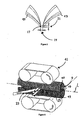
- the corrugated sheath 9 is obtained by extrusion molding a tube of thermoplastic material curved oblong shape, and cutting a longitudinal strip of this tube.
- thermoplastic material for example a polypropylene
- an extrusion temperature of the order of 190 ° C minimum
- An extrusion nozzle 12 mounted in a die 11 gives it the shape of an oblong tube 5 bent along a median plane 29.
- the extrusion nozzle 12 has a bend 14 in its median plane 29 to extrude the curved oblong tube 5 into a first tubular part 51 and a second tubular portion 52 of the same diameter D and integral in the median plane of bending 29.
- This tube 5 is blown and cooled in a molding machine 7 against the walls of two paired molds 47,49 having the shape of half-shells 13 having a corrugated profile 48 and advancing in the extrusion direction and facing a joint plane 13 along the length of the tube 5, to give it an annular wall.
- the annular profile 48 of two paired half-shells 47, 49 also have a bend 14 in their median plane 29 for molding the corrugations 43, 45 simultaneously in the two tubular portions 51, 52.
- the extrusion nozzle 12 and the annular profile 48 of the two paired molds 47, 49 have a section which is in two circles whose centers 01, 02 are brought together to create an overlap in their plane. median 29.
- each pair of half-shells 13 for molding the tube 5 has on the profile 48 of one of the 49 half-shells a flat area 15 in the median plane of bending 29.
- This flat area 15 makes it possible to mold a tube 5 comprising a longitudinal non-corrugated strip 17, the thickness 21 and the width 19 allow it to maintain sufficient flexibility to play a hinge role by plastic deformation, while not excessively stiffening the sheath 9.
- the thickness 21 is equal to 0.4 mm
- the width 19 is equal to 0.45 mm.
- the corrugated sheath 9 is fed by a pulling system 41 to two cutter blades 25 to cut and remove a strip of material 23 longitudinally opposite to the longitudinal flat strip 17 forming a hinge.
- the cutter blades 25 may be replaced by a rotating blade system.
- the strip of material is removed from the wall opposite to the flat zone 17 to form two open shells 33,37, from the first 51 and second 52 tubular parts of the curved oblong tube 5.
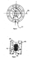
- the two shells, said outer 33 and inner 37 therefore have the same diameter D and are secured by the longitudinal band not hinged 17 forming hinge.
- the outer shell 33 has an opening E1 smaller than the diameter D to fit on the inner shell 37 by pivoting around the hinge 17.
- the opening E1 of the outer shell 33 extends from the hinge 17 to the edge of opposite shell, formed by cutting the strip of material 23.
- the pivoting of the two shells 33,37 around the hinge 17 simultaneously allows the outer shell to slide on the inner shell and the inner shell to slide under the hull exterior.
- the elastic deformation of the opening E1 of the outer shell 33 to the point of passage corresponding to the diameter D of the inner shell 37 is thus reduced. As a result, closing the sheath by insertion is easier.
- the cutout is off-axis with respect to the median plane of bending 29, that is to say that the cutting means 25 is arranged asymmetrically with respect to the median bending plane 29, to form, in the inner shell 37, an opening E2 smaller than that E1 formed in the outer shell 33.
- the opening E2 of the inner shell 37 extends from the hinge 17 to an opposite shell edge 38, formed by cutting the strip of material 23. This arrangement further facilitates the relative pivoting of the two shells 33, 37 around the hinge 17 in the closed position.
- the distance 27 between the median bending plane 29 and the shell edge 34 of the outer shell 33 is equal to 9 mm, and the distance 31 between the median bending plane 29 and the shell edge 38 of the inner shell is equal to 2.5 mm.
- the distance 27 must be sufficient to allow easy insertion of the cable bundle 35 to be protected, but not too great so that the protective sheath is maintained in the closed position when the outer portion covers the inner portion.
- the sheath thus obtained consisting of an inner shell 37 and an outer shell 33 is placed by the operator on the cable harness to be protected.
- the outer shell 33 pivots around the hinge 17 to fit on the inner shell 37 by elastic deformation in extension of the opening E1 of the outer shell 33 and elastic deformation in compression of the opening E2 of the inner shell 37.
- the corrugations 45 of the outer shell 33 are inserted into the corrugations 43 of the inner shell 37.
- the outer shell 33 covers the inner shell 37 on a corner sector 39.
- the overlap angle 39 is defined by the shell edges 34, 38 of the two shells, opposite the hinge 17.
- the recovery angle is between 145 ° and 155 °, and preferably equal to 150 °.
- the outer shell 33 has two different annealing heights H1 and H2, counted from the same peak-to-peak diameter D, to form a recess 41 equal to the wall thickness S of the inner shell 37.
- the outer shell 33 has the height of annealing H1.
- the height of The annulus is H2, smaller than H1.
- the ring height H2 of the outer shell 33, increased by the wall thickness S of the inner shell 37, is equal, along the arc where the overlap is present, to the corrugation height H1 of the outer shell 33, along the arc where the overlap is not present.
- the two paired molds 47, 49 have a corrugated profile 48 at two annealing heights, counted from the same diameter corresponding to the diameter D of the two tubular portions 51, 52 of the molded tube 5, and having between them a difference chosen to correspond to the thickness S of the corrugated wall 43 of one 51 of the two tubular portions 51 and 52 forming the inner shell 37.
Landscapes
- Engineering & Computer Science (AREA)
- Mechanical Engineering (AREA)
- General Engineering & Computer Science (AREA)
- Structural Engineering (AREA)
- Architecture (AREA)
- Civil Engineering (AREA)
- Manufacturing & Machinery (AREA)
- Life Sciences & Earth Sciences (AREA)
- Forests & Forestry (AREA)
- Details Of Indoor Wiring (AREA)
- Extrusion Moulding Of Plastics Or The Like (AREA)
- Shaping Of Tube Ends By Bending Or Straightening (AREA)
- Containers And Plastic Fillers For Packaging (AREA)
- Wing Frames And Configurations (AREA)
Claims (5)
- Röhrenartige Umhüllung mit Ringstruktur, die zwei offene Schalen (33, 37), nämlich eine äußere (33) und eine innere (37), die einstückig mit einem Gelenk (17) ausgebildet sind, um sich durch Schwenken um das Gelenk (17) ineinander einzufügen, mit demselben Durchmesser (D) aufweist und von denen eine, die äußere Schale (33), eine Öffnung (E1) aufweist, die sich von dem Gelenk (17) bis zu einem gegenüberliegenden Schalenrand (34) erstreckt, um sich durch elastische Verformung in die innere Schale (37) in einer Schließstellung einzufügen, wobei während dieses Einfügens die Öffnung (E1) der äußeren Schale (33) sich durch Zug verformt bis sie einen Punkt passiert, der dem Durchmesser (D) der inneren Schale (37) entspricht, und nach diesem Punkt in die nicht ausgezogene Stellung zurückkehrt, wobei die Öffnung (E1) der äußeren Schale (33) kleiner als der Durchmesser (D) ist, wobei die beiden Schalen (33,37) die Form von zwei offenen Schalen eines Kreisabschnitts aufweisen aus einem ersten (51) und einem zweiten (52) röhrenartigen Teil mit Ringstruktur, die von einem länglichen gekrümmten Rohr (5) stammen,
dadurch gekennzeichnet, dass sich die beiden Schalen (33, 37) in der Schließstellung mit einem Überdeckungswinkel (39) überdecken, der durch die beiden gegenüberliegenden Schalenränder (34, 38) gebildet ist und zwischen 145° und 155° liegt. - Röhrenartige Umhüllung mit Ringstruktur nach Anspruch 1, dadurch gekennzeichnet, dass die innere Schale (33) eine Öffnung (E2) aufweist, die sich von dem Gelenk (17) bis zu einem gegenüberliegenden Schalenrand (38) erstreckt und kleiner als die Öffnung (E1) der äußeren Schale (33) ist.
- Vorrichtung zum Herstellen einer röhrenartigen Umhüllung mit Ringstruktur nach den Ansprüchen 1 bis 2, die einen Extruder (1) mit einer Extrudierdüse (12) zum Extrudieren einer Röhre (5), ein Formwerkzeug (7) mit Formen (47, 49) aufweist, die jeweils ein Profil mit Ringstruktur (48) aufweisen und entsprechend einer gleichen Schließebene (13) zusammengefügt werden, um die Röhre (5) als eine Röhre mit einer Wand mit Ringstruktur (43, 45) zu formen, dadurch gekennzeichnet, dass die Extrudierdüse (12) und das Profil mit Ringstruktur (48) der beiden zusammengesetzten Formen (47, 49) jeweils eine Krümmung (14) in einer Medianebene (29) aufweisen, um jeweils die Röhre (5) in zwei röhrenartigen Teilen (51, 52) mit gleichem Durchmesser (D) sowie einstückig in der Medianebene der Krümmung (29) zu extrudieren und um die Ringstruktur (43, 45) gleichzeitig in den beiden röhrenartigen Teilen (51, 52) zu formen, wobei das Profil mit Ringstruktur (48) der einen (49) der beiden zusammengesetzten Formen einen Bereich frei von einer Ringstruktur (15) in der Medianebene der Krümmung (29) aufweist, um einen Abschnitt der Wand in Längsrichtung frei von einer Ringstruktur (17) zu belassen, wobei ein Abtrennmittel (25) vorhanden ist, um einen Materialstreifen in Längsrichtung (23) beiderseits der Medianebene der Krümmung (29) gegenüber dem Abschnitt in Längsrichtung frei von einer Ringstruktur (17) abzutrennen, um zwei Schalen (33, 37) eines Kreisabschnitts mit gleichem Durchmesser (D) zu bilden, die einstückig mit dem Abschnitt in Längsrichtung frei von einer Ringstruktur (17) sind, der das Gelenk bildet, und von denen jede mit einer Öffnung (E1, E2) versehen ist, die sich von dem Gelenk (17) bis zu einem gegenüberliegenden Schalenrand (34, 38) erstreckt, der durch das Abtrennen des Materialstreifens in Längsrichtung (23) entstanden ist.
- Vorrichtung nach Anspruch 3, dadurch gekennzeichnet, dass die Extrudierdüse (12) und das Profil mit Ringstruktur (48) der beiden zusammengefügten Formen (47, 49) einen Abschnitt aufweisen, der in zwei Kreisen liegt, deren Mittelpunkte (01, 02) aneinander angenähert sind, um eine Überlappung in einer Medianebene zu bewirken
- Vorrichtung nach Anspruch 3 oder 4, dadurch gekennzeichnet, dass das Abtrennmittel (25) asymmetrisch in Bezug auf die Medianebene der Krümmung (29) angeordnet ist
Applications Claiming Priority (2)
| Application Number | Priority Date | Filing Date | Title |
|---|---|---|---|
| FR0606089A FR2903475B1 (fr) | 2006-07-05 | 2006-07-05 | Gaine tubulaire annelee de protection comprenant une charniere et dispositif pour fabriquer une telle gaine |
| PCT/EP2007/005937 WO2008003485A1 (fr) | 2006-07-05 | 2007-07-05 | Gaine tubulaire annelee et dispositif pour fabriquer une telle gaine |
Publications (3)
| Publication Number | Publication Date |
|---|---|
| EP2035735A1 EP2035735A1 (de) | 2009-03-18 |
| EP2035735B1 EP2035735B1 (de) | 2010-10-13 |
| EP2035735B2 true EP2035735B2 (de) | 2014-09-17 |
Family
ID=37733738
Family Applications (1)
| Application Number | Title | Priority Date | Filing Date |
|---|---|---|---|
| EP07785904.9A Active EP2035735B2 (de) | 2006-07-05 | 2007-07-05 | Beringte rohrförmige ummantelung und verfahren zur herstellung einer derartigen ummantelung |
Country Status (10)
| Country | Link |
|---|---|
| US (1) | US7891383B2 (de) |
| EP (1) | EP2035735B2 (de) |
| JP (1) | JP5198444B2 (de) |
| CN (1) | CN101484741B (de) |
| AT (1) | ATE484704T1 (de) |
| BR (1) | BRPI0713230B8 (de) |
| DE (1) | DE602007009837D1 (de) |
| FR (1) | FR2903475B1 (de) |
| RU (1) | RU2436008C2 (de) |
| WO (1) | WO2008003485A1 (de) |
Cited By (3)
| Publication number | Priority date | Publication date | Assignee | Title |
|---|---|---|---|---|
| EP3125383A1 (de) | 2015-07-27 | 2017-02-01 | Schlemmer Gmbh | Aufklappbarer wellschlauch, kabelbaum und verfahren zum herstellen eines derartigen aufklappbaren wellschlauchs |
| DE102015112272A1 (de) | 2015-07-27 | 2017-02-02 | Schlemmer Gmbh | Aufklappbarer Wellschlauch, Kabelbaum und Verfahren zum Herstellen eines derartigen aufklappbaren Wellschlauchs |
| DE102016123040A1 (de) | 2016-11-29 | 2018-05-30 | Schlemmer Gmbh | Aufklappbarer Wellschlauch und Kabelbaum |
Families Citing this family (16)
| Publication number | Priority date | Publication date | Assignee | Title |
|---|---|---|---|---|
| DE102006005720B3 (de) * | 2006-02-08 | 2007-05-16 | Wampfler Ag | Endklemme für eine Schleppleitung |
| FR2935556B1 (fr) * | 2008-09-03 | 2010-10-08 | Delfingen Fr Anteuil S A | Gaine tubulaire annelee etanche et procede et installation de fabrication |
| FR2935555B1 (fr) * | 2008-09-03 | 2010-10-08 | Delfingen Fr Anteuil S A | Gaine tubulaire annelee a protection contre l'abrasion et procede et installation de fabrication |
| JP5798775B2 (ja) | 2011-04-04 | 2015-10-21 | 矢崎総業株式会社 | コルゲートチューブ |
| GB2500669B (en) * | 2012-03-29 | 2016-03-30 | Icon Polymer Group | Hose for conveying fluid |
| CN102832489A (zh) * | 2012-08-28 | 2012-12-19 | 中航光电科技股份有限公司 | 一种低损耗电连接器 |
| JP6171244B2 (ja) * | 2013-12-27 | 2017-08-02 | 古河樹脂加工株式会社 | コルゲート管、ケーブル構造、コルゲート管の製造方法およびコルゲート管素材の製造方法 |
| FR3017178B1 (fr) * | 2014-02-06 | 2016-09-02 | Delfingen Fr-Anteuil S A | Gaine tubulaire annelee comportant un moyen de serrage interieur |
| DE102014108757A1 (de) * | 2014-06-23 | 2015-12-24 | Schlemmer Gmbh | Wellrohr aus Kunststoff zum Ummanteln von Leitungen sowie Verfahren zur Herstellung eines solchen Wellrohres |
| FR3024922B1 (fr) * | 2014-08-13 | 2018-04-20 | Delfingen Fr Anteuil Sa | Gaine tubulaire annelee a bande longitudinale detachable |
| DE102014116447A1 (de) | 2014-11-11 | 2016-05-12 | Schlemmer Gmbh | Wellrohranordnung zur Aufnahme von Leitungen und Verfahren zur Herstellung einer solchen Wellrohranordnung |
| US10288197B2 (en) * | 2016-07-11 | 2019-05-14 | Benjamin Grossman | Conduit with latch system |
| DE102017105787B3 (de) * | 2017-03-17 | 2018-06-28 | Schlemmer Holding GmbH | Verbundschlauch |
| WO2020114959A1 (en) * | 2018-12-03 | 2020-06-11 | Swiss Inventix Gmbh | Method for the application of a tubular hull to an electric cable |
| JP7587552B2 (ja) * | 2022-06-30 | 2024-11-20 | 矢崎総業株式会社 | 外装材、外装材連結体、ワイヤハーネス、及びワイヤハーネスの製造方法 |
| CN114992391A (zh) * | 2022-08-04 | 2022-09-02 | 广州兴杭塑胶制品有限公司 | 一种新型防火绝热的托码及其制备方法 |
Citations (2)
| Publication number | Priority date | Publication date | Assignee | Title |
|---|---|---|---|---|
| EP0952652B1 (de) † | 1998-04-17 | 2004-09-29 | Fränkische Rohrwerke Gebr. Kirchner GmbH & Co. | Wellrohr mit überlappenden Flügelabschnitten |
| US6938645B2 (en) † | 2001-04-25 | 2005-09-06 | Sofanou S.A. | Protective sheath having a longitudinal strip made of flexible material, and method of manufacturing such a sheath |
Family Cites Families (14)
| Publication number | Priority date | Publication date | Assignee | Title |
|---|---|---|---|---|
| JPS5313038Y2 (de) * | 1973-08-24 | 1978-04-08 | ||
| US4194081A (en) * | 1977-10-11 | 1980-03-18 | Dayco Corporation | Vaccum cleaner hose construction having electrical conductors extending therealong and method of making same |
| US4296157A (en) * | 1978-12-05 | 1981-10-20 | Conti Allen C | Tube with weakened side wall segment |
| DE3640226A1 (de) * | 1986-11-25 | 1988-06-01 | Kirchner Fraenk Rohr | Kunststoff-schutzrohranordnung fuer leitungen |
| JPH04137423U (ja) * | 1991-04-03 | 1992-12-22 | 矢崎総業株式会社 | オーバーラツプ型コルゲートチユーブ |
| FR2745429B1 (fr) * | 1996-02-28 | 1998-04-17 | Sofanou Sa | Gaine annelee fendue |
| US6078009A (en) * | 1997-02-21 | 2000-06-20 | Sumitomo Wiring Systems, Ltd. | Corrugated tube |
| US5942729A (en) * | 1997-08-04 | 1999-08-24 | The Siemon Company | Double hinged raceway |
| JP2000115942A (ja) * | 1998-10-02 | 2000-04-21 | Yazaki Corp | コルゲートチューブ |
| JP3883398B2 (ja) * | 2001-06-12 | 2007-02-21 | 矢崎総業株式会社 | コルゲートチューブ及びその形成方法 |
| JP3949396B2 (ja) * | 2001-06-12 | 2007-07-25 | 矢崎総業株式会社 | コルゲートチューブ |
| JP4330849B2 (ja) * | 2002-07-05 | 2009-09-16 | 未来工業株式会社 | ケーブル保護カバーの製造方法 |
| RU2251183C2 (ru) * | 2002-12-23 | 2005-04-27 | Открытое акционерное общество "Самарский завод электромонтажных изделий" | Устройство для монтажа кабеля |
| JP2006014398A (ja) * | 2004-06-22 | 2006-01-12 | Sumitomo Wiring Syst Ltd | ワイヤハーネス用コルゲートチューブ |
-
2006
- 2006-07-05 FR FR0606089A patent/FR2903475B1/fr not_active Expired - Fee Related
-
2007
- 2007-07-05 BR BRPI0713230A patent/BRPI0713230B8/pt active IP Right Grant
- 2007-07-05 WO PCT/EP2007/005937 patent/WO2008003485A1/fr not_active Ceased
- 2007-07-05 JP JP2009517041A patent/JP5198444B2/ja not_active Expired - Fee Related
- 2007-07-05 EP EP07785904.9A patent/EP2035735B2/de active Active
- 2007-07-05 RU RU2008151294/06A patent/RU2436008C2/ru active IP Right Revival
- 2007-07-05 CN CN200780025160XA patent/CN101484741B/zh active Active
- 2007-07-05 AT AT07785904T patent/ATE484704T1/de not_active IP Right Cessation
- 2007-07-05 DE DE602007009837T patent/DE602007009837D1/de active Active
-
2009
- 2009-01-02 US US12/348,069 patent/US7891383B2/en active Active
Patent Citations (2)
| Publication number | Priority date | Publication date | Assignee | Title |
|---|---|---|---|---|
| EP0952652B1 (de) † | 1998-04-17 | 2004-09-29 | Fränkische Rohrwerke Gebr. Kirchner GmbH & Co. | Wellrohr mit überlappenden Flügelabschnitten |
| US6938645B2 (en) † | 2001-04-25 | 2005-09-06 | Sofanou S.A. | Protective sheath having a longitudinal strip made of flexible material, and method of manufacturing such a sheath |
Cited By (6)
| Publication number | Priority date | Publication date | Assignee | Title |
|---|---|---|---|---|
| EP3125383A1 (de) | 2015-07-27 | 2017-02-01 | Schlemmer Gmbh | Aufklappbarer wellschlauch, kabelbaum und verfahren zum herstellen eines derartigen aufklappbaren wellschlauchs |
| DE102015112272A1 (de) | 2015-07-27 | 2017-02-02 | Schlemmer Gmbh | Aufklappbarer Wellschlauch, Kabelbaum und Verfahren zum Herstellen eines derartigen aufklappbaren Wellschlauchs |
| DE102015112272B4 (de) * | 2015-07-27 | 2020-12-17 | Schlemmer Gmbh | Aufklappbarer Wellschlauch, Kabelbaum und Verfahren zum Herstellen eines derartigen aufklappbaren Wellschlauchs |
| DE102016123040A1 (de) | 2016-11-29 | 2018-05-30 | Schlemmer Gmbh | Aufklappbarer Wellschlauch und Kabelbaum |
| WO2018099686A1 (de) | 2016-11-29 | 2018-06-07 | Schlemmer Gmbh | Aufklappbarer wellschlauch und kabelbaum |
| US11101626B2 (en) | 2016-11-29 | 2021-08-24 | Schlemmer Gmbh | Corrugated tube that can be folded open and wiring harness |
Also Published As
| Publication number | Publication date |
|---|---|
| CN101484741A (zh) | 2009-07-15 |
| BRPI0713230A2 (pt) | 2012-04-10 |
| WO2008003485A9 (fr) | 2009-02-26 |
| US20090140105A1 (en) | 2009-06-04 |
| CN101484741B (zh) | 2012-06-13 |
| BRPI0713230B8 (pt) | 2018-12-11 |
| US7891383B2 (en) | 2011-02-22 |
| DE602007009837D1 (de) | 2010-11-25 |
| ATE484704T1 (de) | 2010-10-15 |
| EP2035735A1 (de) | 2009-03-18 |
| FR2903475B1 (fr) | 2011-10-21 |
| RU2008151294A (ru) | 2010-08-20 |
| EP2035735B1 (de) | 2010-10-13 |
| FR2903475A1 (fr) | 2008-01-11 |
| JP2009542180A (ja) | 2009-11-26 |
| RU2436008C2 (ru) | 2011-12-10 |
| JP5198444B2 (ja) | 2013-05-15 |
| WO2008003485A1 (fr) | 2008-01-10 |
Similar Documents
| Publication | Publication Date | Title |
|---|---|---|
| EP2035735B1 (de) | Beringte rohrförmige ummantelung und verfahren zur herstellung einer derartigen ummantelung | |
| EP2007564A1 (de) | Verfahren und vorrichtung zur herstellung einer anordnung aus zwei ringhülsen, die zur herstellung einer einzigen ringhülse voneinander getrennt werden können | |
| EP0883922B1 (de) | Geschlitztes wellrohr | |
| EP1382102B1 (de) | Schutzummantelung mit einem longitudinalen streifen aus flexiblen material sowie sein herstellungsverfahren | |
| EP2805393B1 (de) | Schutzmantel, insbesondere für stromkabel, und verfahren zu seiner herstellung | |
| EP2535991A1 (de) | Schutzleitung, insbesondere für die Verlegung von Stromkabeln | |
| EP2719040B1 (de) | Winkelanschlussteil für einen drahtkabelkanal | |
| EP2670010A1 (de) | Elektrischer Schaltschrank, der eine Eingangsvorrichtung eines Leitungskanals umfasst | |
| FR2730785A1 (fr) | Gaine de protection souple en caoutchouc pour assurer le passage d'un faisceau electrique ou d'un conduit | |
| FR3059928A1 (fr) | Procede de production d'un produit moule par extrusion pour des automobiles | |
| EP3463954A1 (de) | Glasplatte mit profilierter dichtung und einem streifen sowie verfahren zur herstellung dieser glasplatte | |
| EP0891897B1 (de) | Flexible Schutzhülle zur Sicherung der Durchfuhr eines elektrischen Kabelbundes zwischen zwei Teilen einer Installation wie einem Kraftfahrzeug | |
| FR2615332A1 (fr) | Tube profile en matiere plastique | |
| WO2019106111A1 (fr) | Pièce de carrosserie comportant un élément optique rapporté par emboitage élastique | |
| FR2895581A1 (fr) | Gaine de protection annelee, fendue et incisee pour former une charniere | |
| FR2976334A1 (fr) | Accessoire d'angle pour chemins de cables en fils | |
| FR2825443A1 (fr) | Gaine tubulaire a charniere | |
| FR2837932A1 (fr) | Cable a fibres optiques et procede de fabrication de ce cable | |
| FR2674798A1 (fr) | Procede de fabrication d'un pare-soleil recouvert d'un revetement et muni d'un bras de support. | |
| FR2705504A1 (fr) | Gaine pour câbles ou fils électriques. | |
| FR2799878A1 (fr) | Outil de gainage d'un faisceau de fils | |
| EP0807506A1 (de) | Verfahren zum Schützen von Rohrleitungen in Kraftfahrzeuganwendungen und Form zur Durchführung des Verfahrens | |
| FR2723662A1 (fr) | Revetement protecteur pour cables plats | |
| FR2732827A1 (fr) | Dispositif de maintien de cables en faisceau | |
| WO2011121203A1 (fr) | Machine et procede de fabrication d'un manchon et manchon ainsi obtenu |
Legal Events
| Date | Code | Title | Description |
|---|---|---|---|
| PUAI | Public reference made under article 153(3) epc to a published international application that has entered the european phase |
Free format text: ORIGINAL CODE: 0009012 |
|
| 17P | Request for examination filed |
Effective date: 20081220 |
|
| AK | Designated contracting states |
Kind code of ref document: A1 Designated state(s): AT BE BG CH CY CZ DE DK EE ES FI FR GB GR HU IE IS IT LI LT LU LV MC MT NL PL PT RO SE SI SK TR |
|
| AX | Request for extension of the european patent |
Extension state: AL BA HR MK RS |
|
| GRAC | Information related to communication of intention to grant a patent modified |
Free format text: ORIGINAL CODE: EPIDOSCIGR1 |
|
| GRAP | Despatch of communication of intention to grant a patent |
Free format text: ORIGINAL CODE: EPIDOSNIGR1 |
|
| GRAS | Grant fee paid |
Free format text: ORIGINAL CODE: EPIDOSNIGR3 |
|
| GRAA | (expected) grant |
Free format text: ORIGINAL CODE: 0009210 |
|
| AK | Designated contracting states |
Kind code of ref document: B1 Designated state(s): AT BE BG CH CY CZ DE DK EE ES FI FR GB GR HU IE IS IT LI LT LU LV MC MT NL PL PT RO SE SI SK TR |
|
| REG | Reference to a national code |
Ref country code: GB Ref legal event code: FG4D Free format text: NOT ENGLISH |
|
| REG | Reference to a national code |
Ref country code: CH Ref legal event code: EP |
|
| REG | Reference to a national code |
Ref country code: IE Ref legal event code: FG4D Free format text: LANGUAGE OF EP DOCUMENT: FRENCH |
|
| REF | Corresponds to: |
Ref document number: 602007009837 Country of ref document: DE Date of ref document: 20101125 Kind code of ref document: P |
|
| REG | Reference to a national code |
Ref country code: RO Ref legal event code: EPE |
|
| REG | Reference to a national code |
Ref country code: NL Ref legal event code: VDEP Effective date: 20101013 |
|
| LTIE | Lt: invalidation of european patent or patent extension |
Effective date: 20101013 |
|
| PG25 | Lapsed in a contracting state [announced via postgrant information from national office to epo] |
Ref country code: LT Free format text: LAPSE BECAUSE OF FAILURE TO SUBMIT A TRANSLATION OF THE DESCRIPTION OR TO PAY THE FEE WITHIN THE PRESCRIBED TIME-LIMIT Effective date: 20101013 |
|
| REG | Reference to a national code |
Ref country code: IE Ref legal event code: FD4D |
|
| PG25 | Lapsed in a contracting state [announced via postgrant information from national office to epo] |
Ref country code: PT Free format text: LAPSE BECAUSE OF FAILURE TO SUBMIT A TRANSLATION OF THE DESCRIPTION OR TO PAY THE FEE WITHIN THE PRESCRIBED TIME-LIMIT Effective date: 20110214 Ref country code: NL Free format text: LAPSE BECAUSE OF FAILURE TO SUBMIT A TRANSLATION OF THE DESCRIPTION OR TO PAY THE FEE WITHIN THE PRESCRIBED TIME-LIMIT Effective date: 20101013 Ref country code: BG Free format text: LAPSE BECAUSE OF FAILURE TO SUBMIT A TRANSLATION OF THE DESCRIPTION OR TO PAY THE FEE WITHIN THE PRESCRIBED TIME-LIMIT Effective date: 20110113 Ref country code: SE Free format text: LAPSE BECAUSE OF FAILURE TO SUBMIT A TRANSLATION OF THE DESCRIPTION OR TO PAY THE FEE WITHIN THE PRESCRIBED TIME-LIMIT Effective date: 20101013 Ref country code: SI Free format text: LAPSE BECAUSE OF FAILURE TO SUBMIT A TRANSLATION OF THE DESCRIPTION OR TO PAY THE FEE WITHIN THE PRESCRIBED TIME-LIMIT Effective date: 20101013 Ref country code: LV Free format text: LAPSE BECAUSE OF FAILURE TO SUBMIT A TRANSLATION OF THE DESCRIPTION OR TO PAY THE FEE WITHIN THE PRESCRIBED TIME-LIMIT Effective date: 20101013 Ref country code: AT Free format text: LAPSE BECAUSE OF FAILURE TO SUBMIT A TRANSLATION OF THE DESCRIPTION OR TO PAY THE FEE WITHIN THE PRESCRIBED TIME-LIMIT Effective date: 20101013 Ref country code: IS Free format text: LAPSE BECAUSE OF FAILURE TO SUBMIT A TRANSLATION OF THE DESCRIPTION OR TO PAY THE FEE WITHIN THE PRESCRIBED TIME-LIMIT Effective date: 20110213 Ref country code: FI Free format text: LAPSE BECAUSE OF FAILURE TO SUBMIT A TRANSLATION OF THE DESCRIPTION OR TO PAY THE FEE WITHIN THE PRESCRIBED TIME-LIMIT Effective date: 20101013 |
|
| PG25 | Lapsed in a contracting state [announced via postgrant information from national office to epo] |
Ref country code: GR Free format text: LAPSE BECAUSE OF FAILURE TO SUBMIT A TRANSLATION OF THE DESCRIPTION OR TO PAY THE FEE WITHIN THE PRESCRIBED TIME-LIMIT Effective date: 20110114 |
|
| PLBI | Opposition filed |
Free format text: ORIGINAL CODE: 0009260 |
|
| PG25 | Lapsed in a contracting state [announced via postgrant information from national office to epo] |
Ref country code: IE Free format text: LAPSE BECAUSE OF FAILURE TO SUBMIT A TRANSLATION OF THE DESCRIPTION OR TO PAY THE FEE WITHIN THE PRESCRIBED TIME-LIMIT Effective date: 20101013 Ref country code: CZ Free format text: LAPSE BECAUSE OF FAILURE TO SUBMIT A TRANSLATION OF THE DESCRIPTION OR TO PAY THE FEE WITHIN THE PRESCRIBED TIME-LIMIT Effective date: 20101013 Ref country code: ES Free format text: LAPSE BECAUSE OF FAILURE TO SUBMIT A TRANSLATION OF THE DESCRIPTION OR TO PAY THE FEE WITHIN THE PRESCRIBED TIME-LIMIT Effective date: 20110124 Ref country code: EE Free format text: LAPSE BECAUSE OF FAILURE TO SUBMIT A TRANSLATION OF THE DESCRIPTION OR TO PAY THE FEE WITHIN THE PRESCRIBED TIME-LIMIT Effective date: 20101013 |
|
| PLAX | Notice of opposition and request to file observation + time limit sent |
Free format text: ORIGINAL CODE: EPIDOSNOBS2 |
|
| 26 | Opposition filed |
Opponent name: FRAENKISCHE INDUSTRIAL PIPES GMBH & CO. KG Effective date: 20110712 |
|
| PG25 | Lapsed in a contracting state [announced via postgrant information from national office to epo] |
Ref country code: PL Free format text: LAPSE BECAUSE OF FAILURE TO SUBMIT A TRANSLATION OF THE DESCRIPTION OR TO PAY THE FEE WITHIN THE PRESCRIBED TIME-LIMIT Effective date: 20101013 Ref country code: DK Free format text: LAPSE BECAUSE OF FAILURE TO SUBMIT A TRANSLATION OF THE DESCRIPTION OR TO PAY THE FEE WITHIN THE PRESCRIBED TIME-LIMIT Effective date: 20101013 Ref country code: SK Free format text: LAPSE BECAUSE OF FAILURE TO SUBMIT A TRANSLATION OF THE DESCRIPTION OR TO PAY THE FEE WITHIN THE PRESCRIBED TIME-LIMIT Effective date: 20101013 |
|
| REG | Reference to a national code |
Ref country code: DE Ref legal event code: R026 Ref document number: 602007009837 Country of ref document: DE Effective date: 20110712 |
|
| PLAF | Information modified related to communication of a notice of opposition and request to file observations + time limit |
Free format text: ORIGINAL CODE: EPIDOSCOBS2 |
|
| PG25 | Lapsed in a contracting state [announced via postgrant information from national office to epo] |
Ref country code: MT Free format text: LAPSE BECAUSE OF FAILURE TO SUBMIT A TRANSLATION OF THE DESCRIPTION OR TO PAY THE FEE WITHIN THE PRESCRIBED TIME-LIMIT Effective date: 20101013 |
|
| BERE | Be: lapsed |
Owner name: DELFINGEN FR-ANTEUIL S.A. Effective date: 20110731 |
|
| PLBB | Reply of patent proprietor to notice(s) of opposition received |
Free format text: ORIGINAL CODE: EPIDOSNOBS3 |
|
| PG25 | Lapsed in a contracting state [announced via postgrant information from national office to epo] |
Ref country code: MC Free format text: LAPSE BECAUSE OF NON-PAYMENT OF DUE FEES Effective date: 20110731 |
|
| REG | Reference to a national code |
Ref country code: CH Ref legal event code: PL |
|
| GBPC | Gb: european patent ceased through non-payment of renewal fee |
Effective date: 20110705 |
|
| PG25 | Lapsed in a contracting state [announced via postgrant information from national office to epo] |
Ref country code: BE Free format text: LAPSE BECAUSE OF NON-PAYMENT OF DUE FEES Effective date: 20110731 Ref country code: LI Free format text: LAPSE BECAUSE OF NON-PAYMENT OF DUE FEES Effective date: 20110731 Ref country code: CH Free format text: LAPSE BECAUSE OF NON-PAYMENT OF DUE FEES Effective date: 20110731 |
|
| PG25 | Lapsed in a contracting state [announced via postgrant information from national office to epo] |
Ref country code: GB Free format text: LAPSE BECAUSE OF NON-PAYMENT OF DUE FEES Effective date: 20110705 |
|
| PG25 | Lapsed in a contracting state [announced via postgrant information from national office to epo] |
Ref country code: LU Free format text: LAPSE BECAUSE OF NON-PAYMENT OF DUE FEES Effective date: 20110705 Ref country code: CY Free format text: LAPSE BECAUSE OF EXPIRATION OF PROTECTION Effective date: 20101013 |
|
| APBM | Appeal reference recorded |
Free format text: ORIGINAL CODE: EPIDOSNREFNO |
|
| APBP | Date of receipt of notice of appeal recorded |
Free format text: ORIGINAL CODE: EPIDOSNNOA2O |
|
| APAH | Appeal reference modified |
Free format text: ORIGINAL CODE: EPIDOSCREFNO |
|
| PG25 | Lapsed in a contracting state [announced via postgrant information from national office to epo] |
Ref country code: HU Free format text: LAPSE BECAUSE OF FAILURE TO SUBMIT A TRANSLATION OF THE DESCRIPTION OR TO PAY THE FEE WITHIN THE PRESCRIBED TIME-LIMIT Effective date: 20101013 |
|
| APBU | Appeal procedure closed |
Free format text: ORIGINAL CODE: EPIDOSNNOA9O |
|
| PUAH | Patent maintained in amended form |
Free format text: ORIGINAL CODE: 0009272 |
|
| STAA | Information on the status of an ep patent application or granted ep patent |
Free format text: STATUS: PATENT MAINTAINED AS AMENDED |
|
| 27A | Patent maintained in amended form |
Effective date: 20140917 |
|
| AK | Designated contracting states |
Kind code of ref document: B2 Designated state(s): AT BE BG CH CY CZ DE DK EE ES FI FR GB GR HU IE IS IT LI LT LU LV MC MT NL PL PT RO SE SI SK TR |
|
| REG | Reference to a national code |
Ref country code: DE Ref legal event code: R102 Ref document number: 602007009837 Country of ref document: DE |
|
| REG | Reference to a national code |
Ref country code: DE Ref legal event code: R102 Ref document number: 602007009837 Country of ref document: DE Effective date: 20140917 |
|
| PGFP | Annual fee paid to national office [announced via postgrant information from national office to epo] |
Ref country code: RO Payment date: 20140801 Year of fee payment: 8 |
|
| PGFP | Annual fee paid to national office [announced via postgrant information from national office to epo] |
Ref country code: TR Payment date: 20140801 Year of fee payment: 8 |
|
| PG25 | Lapsed in a contracting state [announced via postgrant information from national office to epo] |
Ref country code: LV Free format text: LAPSE BECAUSE OF FAILURE TO SUBMIT A TRANSLATION OF THE DESCRIPTION OR TO PAY THE FEE WITHIN THE PRESCRIBED TIME-LIMIT Effective date: 20140917 |
|
| PG25 | Lapsed in a contracting state [announced via postgrant information from national office to epo] |
Ref country code: RO Free format text: LAPSE BECAUSE OF NON-PAYMENT OF DUE FEES Effective date: 20150705 |
|
| REG | Reference to a national code |
Ref country code: FR Ref legal event code: PLFP Year of fee payment: 10 |
|
| REG | Reference to a national code |
Ref country code: FR Ref legal event code: PLFP Year of fee payment: 11 |
|
| PG25 | Lapsed in a contracting state [announced via postgrant information from national office to epo] |
Ref country code: TR Free format text: LAPSE BECAUSE OF NON-PAYMENT OF DUE FEES Effective date: 20150705 |
|
| REG | Reference to a national code |
Ref country code: FR Ref legal event code: PLFP Year of fee payment: 12 |
|
| PGFP | Annual fee paid to national office [announced via postgrant information from national office to epo] |
Ref country code: FR Payment date: 20230720 Year of fee payment: 17 |
|
| PGFP | Annual fee paid to national office [announced via postgrant information from national office to epo] |
Ref country code: DE Payment date: 20240702 Year of fee payment: 18 |
|
| PGFP | Annual fee paid to national office [announced via postgrant information from national office to epo] |
Ref country code: IT Payment date: 20240723 Year of fee payment: 18 |
|
| PG25 | Lapsed in a contracting state [announced via postgrant information from national office to epo] |
Ref country code: FR Free format text: LAPSE BECAUSE OF NON-PAYMENT OF DUE FEES Effective date: 20240731 |
|
| REG | Reference to a national code |
Ref country code: DE Ref legal event code: R119 Ref document number: 602007009837 Country of ref document: DE |
|
| PG25 | Lapsed in a contracting state [announced via postgrant information from national office to epo] |
Ref country code: DE Free format text: LAPSE BECAUSE OF NON-PAYMENT OF DUE FEES Effective date: 20260203 |