EP2036611B1 - Bille de broyage pour un moulin à bague de roulement à billes - Google Patents
Bille de broyage pour un moulin à bague de roulement à billes Download PDFInfo
- Publication number
- EP2036611B1 EP2036611B1 EP07018011A EP07018011A EP2036611B1 EP 2036611 B1 EP2036611 B1 EP 2036611B1 EP 07018011 A EP07018011 A EP 07018011A EP 07018011 A EP07018011 A EP 07018011A EP 2036611 B1 EP2036611 B1 EP 2036611B1
- Authority
- EP
- European Patent Office
- Prior art keywords
- central body
- grinding
- spherical
- grinding ball
- ball
- Prior art date
- Legal status (The legal status is an assumption and is not a legal conclusion. Google has not performed a legal analysis and makes no representation as to the accuracy of the status listed.)
- Not-in-force
Links
Images


Classifications
-
- B—PERFORMING OPERATIONS; TRANSPORTING
- B02—CRUSHING, PULVERISING, OR DISINTEGRATING; PREPARATORY TREATMENT OF GRAIN FOR MILLING
- B02C—CRUSHING, PULVERISING, OR DISINTEGRATING IN GENERAL; MILLING GRAIN
- B02C15/00—Disintegrating by milling members in the form of rollers or balls co-operating with rings or discs
- B02C15/004—Shape or construction of rollers or balls
- B02C15/005—Rollers or balls of composite construction
-
- B—PERFORMING OPERATIONS; TRANSPORTING
- B02—CRUSHING, PULVERISING, OR DISINTEGRATING; PREPARATORY TREATMENT OF GRAIN FOR MILLING
- B02C—CRUSHING, PULVERISING, OR DISINTEGRATING IN GENERAL; MILLING GRAIN
- B02C15/00—Disintegrating by milling members in the form of rollers or balls co-operating with rings or discs
- B02C15/004—Shape or construction of rollers or balls
Definitions
- the invention relates to a grinding ball for a ball mill with a plurality of Kungelkalotten to form a spherical shape, such as this example DE1507628A is known.
- Ball ring mills have a Mahlspur along whicher.die grinding balls perform a grinding movement.
- Ground material, such as coal, is passed into the milling track and ground by the grinding balls moving along the milling track.
- known ball mill grinding balls are used, which are made as a metal casting in one piece.
- the grinding balls are mostly hollow spheres, which may have a diameter of, for example, 120 cm and a wall thickness of, for example, 20 cm.
- the milling balls wear out due to the grinding process. If the wall thickness has been reduced to, for example, 7 cm, the wear limit has been reached and the grinding balls must be replaced.
- the worn grinding balls are disposed of and replaced with completely newly prepared grinding balls.
- the invention is based on the object to present a grinding ball for a ball mill, which is easier to manufacture and with the maintenance of a ball mill is facilitated.
- the object is solved by the features of claim 1.
- Advantageous embodiments can be found in the subclaims.
- the grinding ball comprises a central body and a plurality of spherical caps.
- the spherical caps are connected to the central body in such a way that the combination of spherical caps and central body forms a spherical shape.
- the Kugelform. represents the outer shape of the grinding ball.
- the term spherical cap refers to any body in which a surface is shaped so that it corresponds to a section of the surface of the grinding ball.
- the central body and the spherical caps can be manufactured individually and transported to the place where the ball ring mill is to be built.
- the cost of producing and transporting the grinding ball is reduced compared to a grinding ball formed integrally as a casting.
- spherical caps are usually made of a very hard material.
- the high hardness of the material is often associated with the material being brittle.
- the probability that the Kugelkalotten break during operation of the ball ring mill, is reduced by the fact that the spherical caps rest with the largest possible area over the entire surface on the central body.
- a proportion of 30%, more preferably 50%, more preferably 70% of the surface of the central body is formed by flat surfaces.
- the spherical caps completely cover the surface of the central body.
- the central body then has no contact with the material to be ground, so there is no wear due to friction between regrind and central body.
- the central body can be reused several times after wear of the spherical caps. By the invention, however, it is not excluded that parts of the central body can rake to the surface of the grinding ball.
- the central body already has the shape of a sphere, so there are no flat surfaces on the surface of the central body.
- the spherical caps then form a layer of uniform thickness on the surface of the central body.
- a grinding ball which was originally manufactured as a one-piece casting, after reaching the wear limit as Central body can be used for a new grinding ball according to the invention.
- the surface of the central body consists entirely of flat surfaces, that is, if the central body is a polyhedron.
- Polyhedra where all surfaces have an identical shape, are called platonic solids.
- platonic solids are the tetrahedron, the hexahedron also called the cube, and the octahedron.
- the central body is a platonic body, this has the advantage that the bearing surfaces of all spherical caps can be identically shaped.
- the spherical caps can have an identical overall shape. The effort in the production of spherical caps decreases.
- a spherical cap with a flat surface is located on the central body, then this spherical cap does not have uniform thickness, but rather is thinner in the edge regions than in the central region.
- the life of a spherical cap is determined by its thinnest point. A sufficient life of the spherical caps results when the spherical caps considered in the radial direction of the grinding ball have a minimum thickness of 50 mm, preferably 100 mm, more preferably 150 mm.
- the thickness of the spherical cap differs only slightly between the peripheral region and the central region.
- the differences in the thickness of the spherical cap are the smaller, the stronger the central body is approximated to the spherical shape.
- a better approach to the spherical shape than with platonic bodies can be achieved by choosing an Archimedean body as the central body.
- Archimedean bodies are polyhedra, where the surface is composed of regular polygons.
- a disadvantage of the approach of the polyhedron to the spherical shape is that the number of planar surfaces increases. If a spherical cap is used for each flat surface, the number of spherical caps also increases at the same time. It is to be weighed in terms of expediency, whether the advantage of the more uniform thickness of the spherical caps outweighs the disadvantage that a larger number of spherical caps is required.
- the central body according to the invention may be a hollow body.
- the central body may be a casting, but it is cheaper to manufacture the central body as a welded construction. If the central body is a polyhedron, it can be welded together from flat plates.
- the spherical cap In the spherical cap, it is most cost-effective to manufacture this as a metal casting. Since the surface of cast components is not completely smooth, the bearing surface with which the spherical cap is placed on the central body should be machined. By machining it can be ensured that the spherical cap rests in the desired manner over its entire surface on the surface of the central body. A reworking of the other surfaces of the spherical cap is not required. Although this requires that at the joint surfaces, where a spherical cap adjacent to another spherical cap, a safety margin of a few millimeters must be maintained. However, it has been shown that this safety distance, located in the Mahlober orientation the grinding ball as Column has no negative impact on the grinding process.
- screw connections can be used, wherein one or more screw connections can be provided for each spherical cap.
- the spherical cap can have a through hole which extends from the surface of the grinding ball to the central body.
- the central body has an internal thread in the extension of the through hole.
- a bolt is inserted through the spherical cap and screwed into the internal thread, so that the spherical cap is firmly connected to the central body.
- the head of the bolt must therefore be designed so that it can hold the spherical cap in spite of the wear process firmly on the central body.
- the spherical cap may have a blind bore concentric with the through bore, which extends beyond the wear limit of the spherical cap into the spherical cap. If the head of the bolt rests on the bottom of the blind bore, there is no risk that it dissolves by welding the spherical cap.
- the Mahlober tastes the spherical cap is smooth, the bolt may be formed so that it fills the blind bore and is flush with the Mahlober constitutional the spherical cap.
- an attack element such as a hexagon, can be welded to the end of the bolt. On the hexagon can be attacked with a tool to turn the bolt out of the central body.
- the disadvantage of this type of screw is the internal thread in the central body.
- the production of the internal thread requires some effort.
- the internal thread is poorly accessible after placing the spherical cap. It can happen, for example, that the bolt is set at an angle and the thread is damaged.
- the screw is therefore designed so that a thread in the central body is not required.
- the through hole in the spherical cap and a corresponding hole in the central body have an elongated cross section.
- the end of a T-shaped bolt, the transverse element of which is adapted to the elongated cross-section of the bore is inserted through the bores into the cavity of the central body and rotated so that the transverse element engages behind the wall of the central body.
- a nut can be screwed onto the other end of the T-shaped bolt, so that the T-shaped bolt is clamped against the inner wall of the central body and the spherical cap is thereby secured to the central body.
- the nut can in turn be designed so that it fills the blind bore.
- Elements of the screw connection which possibly extend beyond the surface of the grinding ball during the screwing process, can be ground off so that they are flush with the surface of the grinding ball. Such a screw connection can be most easily achieved by heating the bolt and the nut so that they melt.
- the nut threaded onto the bolt has a greater radial extent than conventional nuts.
- the mother itself is tightened only hand-tight, the actual tension is generated by a plurality of screws which are screwed through the outer area of the nut.
- the screws are supported by their end at the bottom of the blind bore, the voltage of the plurality of screws is transferred to the bolt.
- the spherical cap can also be made of a ceramic material.
- An advantage of an adhesive connection is that a flat connection between the spherical cap and the central body is produced. It is disadvantageous that adhesive bonds are difficult to release again.
- the invention further relates to a ball mill equipped with the grinding balls according to the invention.
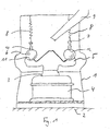
- a housing 1 a in Fig. 1 shown ball mill is arranged on a foundation 2.
- a shaft 3 is mounted, with a Mahlring 5 is connected.
- the Mahlring 5 forms a Mahlspur 11, rest on the grinding balls 6.
- a pressure ring 7 is supported via spring elements 8.
- Mahlbelag 10 is arranged with a pressure track 12. Via the pressure track 12, the pressure ring 7 rests on the grinding balls 6 and exerts a pressure on the grinding balls 6, so that the grinding balls 6 rest on the grinding track 11 with a pressure suitable for the grinding process.
- About a pipe 9 of the ball mill grinding material can be supplied.
- a motor 4 drives the shaft 3, so that the grinding ring 5 is set in rotation.
- the grinding balls 6 are set in motion by the rotating grinding ring 5, so that they roll along the grinding track 11. From the tube 9 emerging ground material falls approximately in the middle of the grinding ring 5 and from there into the Mahlspur 11. From the rolling along the Mahlspur 11 rolling balls 6, the millbase is crushed and passed into the lying outside of the grinding ring 5 annulus. Means may be provided by means of which the not yet sufficiently comminuted material to be ground is returned to the grinding process.
- a grinding ball 6 according to the invention comprises according to FIGS. 2 and 3 a central body 13 and a plurality of spherical caps 14.
- the diameter of the grinding ball 6 is about 120 cm.
- the in Fig. 2 Cube-shaped central body 13 is welded together from six flat steel plates 15.
- the spherical caps 14 are connected to the central body 13 connected, so that the spherical caps 14 form a total of a spherical surface.
- the spherical caps 14 are shaped so that they do not abut each other directly, but that in each case there is a small distance to the adjacent spherical cap 14. By this distance, which is in the surface of the grinding ball 6 as gap. 16, the grinding performance of the grinding balls 6 is not affected.
- Fig. 2 the grinding ball 6 is shown in new condition.
- the thickness of the spherical caps 14 is reduced.
- Has the thickness of the spherical caps 14 to the wear limit 17 is reduced, a maintenance of the ball mill is due.
- the worn spherical caps 14 can be detached from the central body 13 and replaced by new spherical caps 14.
- the central body 13 is spherical.
- the spherical caps 14 have a uniform thickness.
- spherical caps 14 can be connected to the central body 13.
- An adhesive bond has the advantage that the spherical caps 14 are connected over their entire area to the central body 13. The release of the spherical caps 14 from the central body 13 is facilitated, however, when the spherical caps 14 are connected via a screw connection with the central body 13.
- the spherical cap 14 has a through opening 22, which is combined with a blind bore 18.
- the blind bore 18 extends deeper into the spherical cap 14 as the wear limit 17.
- a screw 19 is passed and screwed into a concentric with the opening 18 thread 20 in the central body 13.
- the spherical cap 14 wears, but also wears the head of the screw 19.
- the bottom 21 of the blind bore 18 is beyond the wear limit 17, it is ensured that the wear of the screw 19 does not cause the spherical cap 14 from the central body 13 releases.
- an attack piece for example in the form of a hexagon, be welded to the head of the screw 19.
- At the attack piece can be attacked with a wrench or with a similar lever to screw the screw 19 from the central body 13 out.
- a disadvantage of this type of attachment is that a thread 20 in the central body 13 is required.
- the thread 20 is susceptible to damage. It may happen that the entire central body 13 can no longer be used just because the thread 20 is damaged.
- FIG. 5 a fastening device is shown in which no thread in the central body 13 is required.
- the through opening 22 is as Fig. 6 shows, elongated in cross-section.
- a T-shaped bolt 23 has a cross member 24 which is formed so that it can be passed through the opening 22.
- the T-shaped bolt 23 can be rotated by 90 °, so that the cross member 24, the wall of the central body 13 is behind.
- the bolt 23 or the threaded sleeve 25 protrude beyond the surface of the spherical cap 14, they are processed so that they are flush with the surface of the spherical cap 14.
- the fixation formed by the T-shaped bolt 23 and the threaded sleeve 25 can most easily be released again by heating the bolt 23 and the threaded sleeve 25 so that they melt.
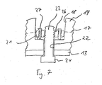
- FIG. 7 An alternative way to tension the T-shaped bolt 23 is in Fig. 7 shown.
- a screw 26 is screwed there only hand-tight on the T-shaped pin 23.
- the actual tension is generated by screws 27 which are screwed through the screw member 26 and which are supported with their end on the bottom 21 of the blind bore 18.
- This type of attachment has the advantage that the T-shaped bolt 23 can be placed under a large tension in the axial direction.
- the spherical cap 14 is particularly stable connected to the central body 13.
Landscapes
- Engineering & Computer Science (AREA)
- Food Science & Technology (AREA)
- Crushing And Grinding (AREA)
Claims (12)
- Boulet de broyage pour un broyeur à boulets annulaire comportant une pluralité de calottes sphériques pour former un moule sphérique, caractérisé en ce qu'il présente un corps central (13) avec lequel les calottes sphériques (14) sont reliées de telle sorte qu'elles reposent entièrement sur le corps central.
- Boulet de broyage selon la revendication 1, caractérisé en ce que les calottes sphériques (14) recouvrent entièrement la surface du corps central (13).
- Boulet de broyage selon la revendication 1, caractérisé en ce qu'une partie de 30%, de préférence 50% et encore de préférence 70% de la surface du corps central (13) est formée de surfaces planes.
- Boulet de broyage selon la revendication 2, caractérisé en ce que le corps central (13) est un polyèdre.
- Boulet de broyage selon l'une des revendications 1 à 4, caractérisé en ce que les calottes sphériques (14) ont, vu dans le sens radial du boulet, une épaisseur minimale de 50 mm, de préférence 100 mm et encore de préférence 150 mm.
- Boulet de broyage selon l'une des revendications 1 à 5, caractérisé en ce que le corps central (13) est un corps creux.
- Boulet de broyage selon l'une des revendications 1 à 6, caractérisé en ce que le corps central (13) est constitué par une construction soudée.
- Boulet de broyage selon l'une des revendications 1 à 7, caractérisé en ce que les calottes sphériques (14) sont réalisées par de pièces moulées et en ce que les partie de la surface des calottes sphériques (14) ne reposant pas sur le corps central (13) restent non usinées.
- Boulet de broyage selon l'une des revendications 1 à 8, caractérisé en ce que la calotte sphérique (14) présente un trou traversant (22) qui est associé à un trou borgne concentrique (18), le trou borgne (18) s'étendant au-delà de la limite d'usure (17) de la calotte sphérique (14) dans la calotte sphérique (14).
- Boulet de broyage selon la revendication 9, caractérisé en ce que le trou traversant (22) est a une section allongée.
- Boulet de broyage selon la revendication 9 ou 10, caractérisé en ce qu'une fixation (23, 26, 27) par laquelle la calotte sphérique (14) est fixée au corps central (13) comporte des vis (27) qui s'appuient par leurs extrémités sur le fond (21) du trou borgne (18).
- Broyeur à boulets annulaire avec une voie de broyage (11) et une pluralité de boulets de broyage (6), dans lequel les boulets de broyage (6) sont disposés pour un déplacement de broyage le long d'une voie de broyage (11) caractérisé en ce que les boulets de broyage (6) sont réalisés selon les revendications 1 à 10.
Priority Applications (3)
| Application Number | Priority Date | Filing Date | Title |
|---|---|---|---|
| AT07018011T ATE448020T1 (de) | 2007-09-13 | 2007-09-13 | Mahlkugel für eine kugelringmühle |
| EP07018011A EP2036611B1 (fr) | 2007-09-13 | 2007-09-13 | Bille de broyage pour un moulin à bague de roulement à billes |
| DE502007001991T DE502007001991D1 (de) | 2007-09-13 | 2007-09-13 | Mahlkugel für eine Kugelringmühle |
Applications Claiming Priority (1)
| Application Number | Priority Date | Filing Date | Title |
|---|---|---|---|
| EP07018011A EP2036611B1 (fr) | 2007-09-13 | 2007-09-13 | Bille de broyage pour un moulin à bague de roulement à billes |
Publications (2)
| Publication Number | Publication Date |
|---|---|
| EP2036611A1 EP2036611A1 (fr) | 2009-03-18 |
| EP2036611B1 true EP2036611B1 (fr) | 2009-11-11 |
Family
ID=39008485
Family Applications (1)
| Application Number | Title | Priority Date | Filing Date |
|---|---|---|---|
| EP07018011A Not-in-force EP2036611B1 (fr) | 2007-09-13 | 2007-09-13 | Bille de broyage pour un moulin à bague de roulement à billes |
Country Status (3)
| Country | Link |
|---|---|
| EP (1) | EP2036611B1 (fr) |
| AT (1) | ATE448020T1 (fr) |
| DE (1) | DE502007001991D1 (fr) |
Families Citing this family (1)
| Publication number | Priority date | Publication date | Assignee | Title |
|---|---|---|---|---|
| CN109622577B (zh) * | 2019-02-01 | 2023-06-16 | 南昌见诚科技有限公司 | 一种安全性能高的电子产品回收破碎设备 |
Family Cites Families (4)
| Publication number | Priority date | Publication date | Assignee | Title |
|---|---|---|---|---|
| DE1507628B1 (de) * | 1966-11-23 | 1969-11-20 | Knorr Bremse Gmbh | Hohlkugel fuer Mahlwerke |
| JPS60104419A (ja) * | 1983-11-12 | 1985-06-08 | Aisin Seiki Co Ltd | 開口覆材の自動開閉装置 |
| JPS62294451A (ja) * | 1986-06-12 | 1987-12-21 | 中央化工機株式会社 | 粉体処理用ボ−ル |
| DE9407444U1 (de) * | 1994-05-04 | 1995-09-07 | Claudius Peters Ag, 21614 Buxtehude | Mühle |
-
2007
- 2007-09-13 AT AT07018011T patent/ATE448020T1/de active
- 2007-09-13 EP EP07018011A patent/EP2036611B1/fr not_active Not-in-force
- 2007-09-13 DE DE502007001991T patent/DE502007001991D1/de active Active
Also Published As
| Publication number | Publication date |
|---|---|
| ATE448020T1 (de) | 2009-11-15 |
| EP2036611A1 (fr) | 2009-03-18 |
| DE502007001991D1 (de) | 2009-12-24 |
Similar Documents
| Publication | Publication Date | Title |
|---|---|---|
| EP1684907B1 (fr) | Cylindre de broyage pour le broyage par pression d'un materiau en grains | |
| EP1077087B1 (fr) | Rouleau broyeur et procédé de fabrication correspondente | |
| EP1991358A1 (fr) | Corps durs pour la protection autogene contre l'usure de surfaces de rouleaux | |
| DE1950372A1 (de) | Befestigungsanordnung mit Senkkopf und Senkloch | |
| EP2825316B1 (fr) | Rouleau de presse | |
| DE102010016286B4 (de) | Auskleidung für Trommelmühlen, insbesondere Kugelmühlen | |
| EP3057709A1 (fr) | Ensemble de réception d'une dent broyeuse sur un cylindre broyeur d'un broyeur | |
| EP2646181B1 (fr) | Système comprenant un disque de pression et un adaptateur pour le montage sur une presse d'extrusion | |
| EP2036611B1 (fr) | Bille de broyage pour un moulin à bague de roulement à billes | |
| DE102011085520B4 (de) | Hammer einer Schlägermühle | |
| EP2036612B1 (fr) | Moulin à bague de roulement à billes | |
| DE2856619C2 (de) | Verbesserter unterer Druckplattenverbund zum Einbau in hydraulisch betätigbare Gesteinszerkleinerer | |
| DE246636C (fr) | ||
| EP2181768A1 (fr) | Moulin à bague de roulement à billes | |
| DE202005010337U1 (de) | Messerträger für Zerkleinerungsvorrichtungen | |
| EP0273172B1 (fr) | Rouleau convoyeur pour l'alimentation d'éléments en bois, en matériaux similaires ou en matière plastique | |
| DE10054232B4 (de) | Werkzeug unter Verwendung von Keramik, insbesondere Fließpreßwerkzeug | |
| DE10018005A1 (de) | Verfahren und Vorrichtung zum Pulverisieren von spanartigem Material | |
| DE467523C (de) | Federkonuskupplung fuer Feinmuehlen | |
| WO2002040167A1 (fr) | Unite d'usure pour bord de paroi d'aube d'un broyeur centrifuge | |
| DE19719310C1 (de) | Schlagleiste | |
| DE202017107052U1 (de) | Mahlbecher und Mahlbecheranordnung zum Zerkleinern eines Mahlgutes und/oder zur Trennung eines Mahlgutes von wenigstens einem Mahlkörper | |
| DE102013107798A1 (de) | Walzenmühle | |
| EP1769163B1 (fr) | Ecrou destine a des vis et boulons soumis a de fortes contraintes | |
| EP0872280A2 (fr) | Revêtement résistant à lùsure pour cylindres de broyeurs à cylindres pour le broyage sous pression de matériau granulaire |
Legal Events
| Date | Code | Title | Description |
|---|---|---|---|
| PUAI | Public reference made under article 153(3) epc to a published international application that has entered the european phase |
Free format text: ORIGINAL CODE: 0009012 |
|
| 17P | Request for examination filed |
Effective date: 20081017 |
|
| AK | Designated contracting states |
Kind code of ref document: A1 Designated state(s): AT BE BG CH CY CZ DE DK EE ES FI FR GB GR HU IE IS IT LI LT LU LV MC MT NL PL PT RO SE SI SK TR |
|
| AX | Request for extension of the european patent |
Extension state: AL BA HR MK RS |
|
| GRAP | Despatch of communication of intention to grant a patent |
Free format text: ORIGINAL CODE: EPIDOSNIGR1 |
|
| GRAS | Grant fee paid |
Free format text: ORIGINAL CODE: EPIDOSNIGR3 |
|
| GRAA | (expected) grant |
Free format text: ORIGINAL CODE: 0009210 |
|
| AK | Designated contracting states |
Kind code of ref document: B1 Designated state(s): AT BE BG CH CY CZ DE DK EE ES FI FR GB GR HU IE IS IT LI LT LU LV MC MT NL PL PT RO SE SI SK TR |
|
| REG | Reference to a national code |
Ref country code: GB Ref legal event code: FG4D Free format text: NOT ENGLISH |
|
| REG | Reference to a national code |
Ref country code: CH Ref legal event code: EP |
|
| AKX | Designation fees paid |
Designated state(s): AT BE BG CH CY CZ DE DK EE ES FI FR GB GR HU IE IS IT LI LT LU LV MC MT NL PL PT RO SE SI SK TR |
|
| REG | Reference to a national code |
Ref country code: IE Ref legal event code: FG4D |
|
| REF | Corresponds to: |
Ref document number: 502007001991 Country of ref document: DE Date of ref document: 20091224 Kind code of ref document: P |
|
| NLV1 | Nl: lapsed or annulled due to failure to fulfill the requirements of art. 29p and 29m of the patents act | ||
| LTIE | Lt: invalidation of european patent or patent extension |
Effective date: 20091111 |
|
| PG25 | Lapsed in a contracting state [announced via postgrant information from national office to epo] |
Ref country code: SE Free format text: LAPSE BECAUSE OF FAILURE TO SUBMIT A TRANSLATION OF THE DESCRIPTION OR TO PAY THE FEE WITHIN THE PRESCRIBED TIME-LIMIT Effective date: 20091111 Ref country code: ES Free format text: LAPSE BECAUSE OF FAILURE TO SUBMIT A TRANSLATION OF THE DESCRIPTION OR TO PAY THE FEE WITHIN THE PRESCRIBED TIME-LIMIT Effective date: 20100222 Ref country code: PT Free format text: LAPSE BECAUSE OF FAILURE TO SUBMIT A TRANSLATION OF THE DESCRIPTION OR TO PAY THE FEE WITHIN THE PRESCRIBED TIME-LIMIT Effective date: 20100311 Ref country code: LT Free format text: LAPSE BECAUSE OF FAILURE TO SUBMIT A TRANSLATION OF THE DESCRIPTION OR TO PAY THE FEE WITHIN THE PRESCRIBED TIME-LIMIT Effective date: 20091111 Ref country code: FI Free format text: LAPSE BECAUSE OF FAILURE TO SUBMIT A TRANSLATION OF THE DESCRIPTION OR TO PAY THE FEE WITHIN THE PRESCRIBED TIME-LIMIT Effective date: 20091111 Ref country code: IS Free format text: LAPSE BECAUSE OF FAILURE TO SUBMIT A TRANSLATION OF THE DESCRIPTION OR TO PAY THE FEE WITHIN THE PRESCRIBED TIME-LIMIT Effective date: 20100311 |
|
| PG25 | Lapsed in a contracting state [announced via postgrant information from national office to epo] |
Ref country code: LV Free format text: LAPSE BECAUSE OF FAILURE TO SUBMIT A TRANSLATION OF THE DESCRIPTION OR TO PAY THE FEE WITHIN THE PRESCRIBED TIME-LIMIT Effective date: 20091111 Ref country code: SI Free format text: LAPSE BECAUSE OF FAILURE TO SUBMIT A TRANSLATION OF THE DESCRIPTION OR TO PAY THE FEE WITHIN THE PRESCRIBED TIME-LIMIT Effective date: 20091111 Ref country code: CY Free format text: LAPSE BECAUSE OF FAILURE TO SUBMIT A TRANSLATION OF THE DESCRIPTION OR TO PAY THE FEE WITHIN THE PRESCRIBED TIME-LIMIT Effective date: 20091111 Ref country code: PL Free format text: LAPSE BECAUSE OF FAILURE TO SUBMIT A TRANSLATION OF THE DESCRIPTION OR TO PAY THE FEE WITHIN THE PRESCRIBED TIME-LIMIT Effective date: 20091111 |
|
| REG | Reference to a national code |
Ref country code: IE Ref legal event code: FD4D |
|
| PG25 | Lapsed in a contracting state [announced via postgrant information from national office to epo] |
Ref country code: RO Free format text: LAPSE BECAUSE OF FAILURE TO SUBMIT A TRANSLATION OF THE DESCRIPTION OR TO PAY THE FEE WITHIN THE PRESCRIBED TIME-LIMIT Effective date: 20091111 Ref country code: IE Free format text: LAPSE BECAUSE OF FAILURE TO SUBMIT A TRANSLATION OF THE DESCRIPTION OR TO PAY THE FEE WITHIN THE PRESCRIBED TIME-LIMIT Effective date: 20091111 Ref country code: EE Free format text: LAPSE BECAUSE OF FAILURE TO SUBMIT A TRANSLATION OF THE DESCRIPTION OR TO PAY THE FEE WITHIN THE PRESCRIBED TIME-LIMIT Effective date: 20091111 Ref country code: BG Free format text: LAPSE BECAUSE OF FAILURE TO SUBMIT A TRANSLATION OF THE DESCRIPTION OR TO PAY THE FEE WITHIN THE PRESCRIBED TIME-LIMIT Effective date: 20100211 Ref country code: DK Free format text: LAPSE BECAUSE OF FAILURE TO SUBMIT A TRANSLATION OF THE DESCRIPTION OR TO PAY THE FEE WITHIN THE PRESCRIBED TIME-LIMIT Effective date: 20091111 |
|
| PG25 | Lapsed in a contracting state [announced via postgrant information from national office to epo] |
Ref country code: SK Free format text: LAPSE BECAUSE OF FAILURE TO SUBMIT A TRANSLATION OF THE DESCRIPTION OR TO PAY THE FEE WITHIN THE PRESCRIBED TIME-LIMIT Effective date: 20091111 Ref country code: CZ Free format text: LAPSE BECAUSE OF FAILURE TO SUBMIT A TRANSLATION OF THE DESCRIPTION OR TO PAY THE FEE WITHIN THE PRESCRIBED TIME-LIMIT Effective date: 20091111 |
|
| PLBE | No opposition filed within time limit |
Free format text: ORIGINAL CODE: 0009261 |
|
| STAA | Information on the status of an ep patent application or granted ep patent |
Free format text: STATUS: NO OPPOSITION FILED WITHIN TIME LIMIT |
|
| 26N | No opposition filed |
Effective date: 20100812 |
|
| PG25 | Lapsed in a contracting state [announced via postgrant information from national office to epo] |
Ref country code: GR Free format text: LAPSE BECAUSE OF FAILURE TO SUBMIT A TRANSLATION OF THE DESCRIPTION OR TO PAY THE FEE WITHIN THE PRESCRIBED TIME-LIMIT Effective date: 20100212 |
|
| PGFP | Annual fee paid to national office [announced via postgrant information from national office to epo] |
Ref country code: FR Payment date: 20100930 Year of fee payment: 4 |
|
| BERE | Be: lapsed |
Owner name: CLAUDIUS PETERS TECHNOLOGIES G.M.B.H. Effective date: 20100930 |
|
| PG25 | Lapsed in a contracting state [announced via postgrant information from national office to epo] |
Ref country code: IT Free format text: LAPSE BECAUSE OF FAILURE TO SUBMIT A TRANSLATION OF THE DESCRIPTION OR TO PAY THE FEE WITHIN THE PRESCRIBED TIME-LIMIT Effective date: 20091111 |
|
| PG25 | Lapsed in a contracting state [announced via postgrant information from national office to epo] |
Ref country code: MC Free format text: LAPSE BECAUSE OF NON-PAYMENT OF DUE FEES Effective date: 20100930 |
|
| REG | Reference to a national code |
Ref country code: DE Ref legal event code: R119 Ref document number: 502007001991 Country of ref document: DE Effective date: 20110401 |
|
| PG25 | Lapsed in a contracting state [announced via postgrant information from national office to epo] |
Ref country code: BE Free format text: LAPSE BECAUSE OF NON-PAYMENT OF DUE FEES Effective date: 20100930 Ref country code: DE Free format text: LAPSE BECAUSE OF NON-PAYMENT OF DUE FEES Effective date: 20110401 |
|
| PG25 | Lapsed in a contracting state [announced via postgrant information from national office to epo] |
Ref country code: MT Free format text: LAPSE BECAUSE OF FAILURE TO SUBMIT A TRANSLATION OF THE DESCRIPTION OR TO PAY THE FEE WITHIN THE PRESCRIBED TIME-LIMIT Effective date: 20091111 |
|
| REG | Reference to a national code |
Ref country code: CH Ref legal event code: PL |
|
| GBPC | Gb: european patent ceased through non-payment of renewal fee |
Effective date: 20110913 |
|
| REG | Reference to a national code |
Ref country code: FR Ref legal event code: ST Effective date: 20120531 |
|
| PG25 | Lapsed in a contracting state [announced via postgrant information from national office to epo] |
Ref country code: CH Free format text: LAPSE BECAUSE OF NON-PAYMENT OF DUE FEES Effective date: 20110930 Ref country code: LI Free format text: LAPSE BECAUSE OF NON-PAYMENT OF DUE FEES Effective date: 20110930 |
|
| PG25 | Lapsed in a contracting state [announced via postgrant information from national office to epo] |
Ref country code: FR Free format text: LAPSE BECAUSE OF NON-PAYMENT OF DUE FEES Effective date: 20110930 Ref country code: GB Free format text: LAPSE BECAUSE OF NON-PAYMENT OF DUE FEES Effective date: 20110913 |
|
| PG25 | Lapsed in a contracting state [announced via postgrant information from national office to epo] |
Ref country code: LU Free format text: LAPSE BECAUSE OF NON-PAYMENT OF DUE FEES Effective date: 20100913 Ref country code: NL Free format text: LAPSE BECAUSE OF FAILURE TO SUBMIT A TRANSLATION OF THE DESCRIPTION OR TO PAY THE FEE WITHIN THE PRESCRIBED TIME-LIMIT Effective date: 20091111 Ref country code: HU Free format text: LAPSE BECAUSE OF FAILURE TO SUBMIT A TRANSLATION OF THE DESCRIPTION OR TO PAY THE FEE WITHIN THE PRESCRIBED TIME-LIMIT Effective date: 20100512 |
|
| PG25 | Lapsed in a contracting state [announced via postgrant information from national office to epo] |
Ref country code: TR Free format text: LAPSE BECAUSE OF FAILURE TO SUBMIT A TRANSLATION OF THE DESCRIPTION OR TO PAY THE FEE WITHIN THE PRESCRIBED TIME-LIMIT Effective date: 20091111 |
|
| REG | Reference to a national code |
Ref country code: AT Ref legal event code: MM01 Ref document number: 448020 Country of ref document: AT Kind code of ref document: T Effective date: 20120913 |
|
| PG25 | Lapsed in a contracting state [announced via postgrant information from national office to epo] |
Ref country code: AT Free format text: LAPSE BECAUSE OF NON-PAYMENT OF DUE FEES Effective date: 20120913 |