EP2036615A2 - Electrofiltre pour une installation d'allumage - Google Patents
Electrofiltre pour une installation d'allumage Download PDFInfo
- Publication number
- EP2036615A2 EP2036615A2 EP08162942A EP08162942A EP2036615A2 EP 2036615 A2 EP2036615 A2 EP 2036615A2 EP 08162942 A EP08162942 A EP 08162942A EP 08162942 A EP08162942 A EP 08162942A EP 2036615 A2 EP2036615 A2 EP 2036615A2
- Authority
- EP
- European Patent Office
- Prior art keywords
- filter
- chimney
- electrostatic precipitator
- ionization chamber
- electrodes
- Prior art date
- Legal status (The legal status is an assumption and is not a legal conclusion. Google has not performed a legal analysis and makes no representation as to the accuracy of the status listed.)
- Withdrawn
Links
Images

Classifications
-
- B—PERFORMING OPERATIONS; TRANSPORTING
- B03—SEPARATION OF SOLID MATERIALS USING LIQUIDS OR USING PNEUMATIC TABLES OR JIGS; MAGNETIC OR ELECTROSTATIC SEPARATION OF SOLID MATERIALS FROM SOLID MATERIALS OR FLUIDS; SEPARATION BY HIGH-VOLTAGE ELECTRIC FIELDS
- B03C—MAGNETIC OR ELECTROSTATIC SEPARATION OF SOLID MATERIALS FROM SOLID MATERIALS OR FLUIDS; SEPARATION BY HIGH-VOLTAGE ELECTRIC FIELDS
- B03C3/00—Separating dispersed particles from gases or vapour, e.g. air, by electrostatic effect
- B03C3/34—Constructional details or accessories or operation thereof
- B03C3/40—Electrode constructions
- B03C3/41—Ionising-electrodes
-
- B—PERFORMING OPERATIONS; TRANSPORTING
- B03—SEPARATION OF SOLID MATERIALS USING LIQUIDS OR USING PNEUMATIC TABLES OR JIGS; MAGNETIC OR ELECTROSTATIC SEPARATION OF SOLID MATERIALS FROM SOLID MATERIALS OR FLUIDS; SEPARATION BY HIGH-VOLTAGE ELECTRIC FIELDS
- B03C—MAGNETIC OR ELECTROSTATIC SEPARATION OF SOLID MATERIALS FROM SOLID MATERIALS OR FLUIDS; SEPARATION BY HIGH-VOLTAGE ELECTRIC FIELDS
- B03C3/00—Separating dispersed particles from gases or vapour, e.g. air, by electrostatic effect
- B03C3/02—Plant or installations having external electricity supply
- B03C3/04—Plant or installations having external electricity supply dry type
- B03C3/08—Plant or installations having external electricity supply dry type characterised by presence of stationary flat electrodes arranged with their flat surfaces parallel to the gas stream
-
- B—PERFORMING OPERATIONS; TRANSPORTING
- B03—SEPARATION OF SOLID MATERIALS USING LIQUIDS OR USING PNEUMATIC TABLES OR JIGS; MAGNETIC OR ELECTROSTATIC SEPARATION OF SOLID MATERIALS FROM SOLID MATERIALS OR FLUIDS; SEPARATION BY HIGH-VOLTAGE ELECTRIC FIELDS
- B03C—MAGNETIC OR ELECTROSTATIC SEPARATION OF SOLID MATERIALS FROM SOLID MATERIALS OR FLUIDS; SEPARATION BY HIGH-VOLTAGE ELECTRIC FIELDS
- B03C3/00—Separating dispersed particles from gases or vapour, e.g. air, by electrostatic effect
- B03C3/34—Constructional details or accessories or operation thereof
- B03C3/86—Electrode-carrying means
-
- B—PERFORMING OPERATIONS; TRANSPORTING
- B03—SEPARATION OF SOLID MATERIALS USING LIQUIDS OR USING PNEUMATIC TABLES OR JIGS; MAGNETIC OR ELECTROSTATIC SEPARATION OF SOLID MATERIALS FROM SOLID MATERIALS OR FLUIDS; SEPARATION BY HIGH-VOLTAGE ELECTRIC FIELDS
- B03C—MAGNETIC OR ELECTROSTATIC SEPARATION OF SOLID MATERIALS FROM SOLID MATERIALS OR FLUIDS; SEPARATION BY HIGH-VOLTAGE ELECTRIC FIELDS
- B03C2201/00—Details of magnetic or electrostatic separation
- B03C2201/08—Ionising electrode being a rod
Definitions
- the invention relates to an electric filter for a firing system, in particular for a domestic firing system, with an ionization chamber with a filter electrode assembly in the flow path of the flue gas, wherein the filter electrode assembly is arranged in a substantially straight portion of the flow path of the flue gas, and a plurality aligned in the direction of flue gas flow and preferably formed as rods or plates spaced apart electrodes, which are arranged parallel to the flow axis of the flow path.
- an electric filter for a combustion plant which has a first and a second swirl chamber for the flue gas.
- a filter electrode assembly is provided with an insulator which is arranged in the purge air flow.
- the electrostatic precipitator further comprises a second vortex chamber which is connected to a tubular outlet of the first vortex chamber and formed so that the particles located in the flue gas are deposited in it.
- the cleaned flue gas can escape from the electrostatic precipitator.
- the filter electrode arrangement has horizontally extending, star-shaped arranged first electrodes and a vertically oriented, emanating from the intersection of the first electrode second electrode. At least part of the electrodes is arranged transversely to the flow.
- an electrostatic filter for a firing system which has a rod-shaped central and arranged in the direction of the flow axis of the flue gas filter electrode, an electrode holder, via which the filter electrode is held in an exhaust pipe of the furnace and supplied with voltage, and an insulator which surrounds the electrode holder.
- two baffle plates, which are arranged on the insulator and a scavenging air opening are provided in the electrostatic precipitator, wherein scavenging air can be guided in the direction of the plate via the scavenging air opening. The purge air is thereby guided so that a particle deposition of the housing is avoided and thus the efficiency of the filter is maintained for a long time.
- This electrostatic precipitator is suitable for installation in a flue gas flow path between the furnace and the chimney.
- the disadvantage is that by the only one central center electrode, the deposition rates, especially for use as a chimney cowl, too low.
- an electrostatic filter for a furnace known, which can be placed for example on a fireplace.
- the electrostatic precipitator consists of a frame, which is placed on the chimney, an insulator that protrudes from the frame inside in the middle of the frame and at the end of a weighted electrode hangs and protrudes into the chimney.
- the electrostatic precipitator is used to hold back the particles in the flue gas.
- a high voltage is applied to the electrode, with the result that the particles are electrostatically charged and reflected by the chimney and the frame.
- this may result in prolonged operation of the electrostatic precipitator, the particles that accumulate on the insulator form an electrically conductive bridge due to their electrical conductivity between the insulator and the frame and thereby degrade the effect of the insulator.
- the WO 1993/16807 A1 discloses an electrostatic filter having an ionization chamber and a filter electrode assembly in the flow path of the gas, wherein the filter electrode assembly is disposed in a substantially straight portion of the flow path of the gas.
- the filter electrode assembly has a plurality of electrodes formed as parallel plates, which are aligned in the direction of gas flow.
- the disadvantage is that the known electrostatic filter arrangement takes up a lot of space and causes a relatively high throttling of the flue gases. For subsequent installation in a chimney, the device is therefore less suitable.
- the object of the invention is to avoid the disadvantages mentioned and to effectively clean the flue gases of domestic fire furnaces in a space-saving manner, with particular attention to be directed to simple retrofitting in existing firing systems.
- the electrodes are connected to one another by a preferably annular conductor comprising the rods or plates.
- the electrodes are advantageously rotationally symmetrical with respect to the flow axis of the flue gas flow, in particular arranged rotationally symmetrical with respect to the center axis of the chimney.
- Electrodes are concentric with the annular conductor. It is particularly advantageous if the electrodes are arranged substantially in a star shape.
- the electrodes formed by plates intersect in the region of the flow axis and are connected to one another.
- the chimney cowl is releasably connected to the chimney, wherein preferably the chimney cowl is attachable to the chimney or hingedly connected thereto by a hinge.
- the ionization chamber is formed by a ceramic inner tube.
- the ceramic inner tube advantageously surrounds the filter electrode arrangement.
- a straight separation region is arranged downstream of and in alignment with the ionization chamber, wherein preferably the separation region is formed by a separator tube, preferably made of stainless steel, whose axis is aligned with the flow axis of the chimney, and when upstream of the ionization chamber, there is disposed a stainless steel insert tube whose axis is aligned with the axis of the ionization chamber and with the axis of the deposition region.
- a removable stainless steel inner tube can be inserted into the separator tube with an exact fit. If necessary, the inner tube can be removed and cleaned or replaced.
- the electrostatic filter has a mounting plate upstream of the ionization chamber.
- Turbulence and turbulence in the area of the filter electrode arrangement have an advantageous effect on the deposition rates.
- the ionization chamber is expanded discontinuously in the transition region to the insertion tube and to the separation region.
- an electrical insulator is arranged around the separation area and around the ionization chamber.
- the ionization chamber is formed by a T-shaped tube, wherein a high-voltage generator, which is conductively connected to the filter electrode arrangement and the deposition region, is subsequently arranged on the opening tube part of the T-tube.
- Fig. 1 shows a chimney 1 on the mouth 2 as a chimney cap 3 trained electrostatic filter 4 is arranged.
- the electrostatic filter 4 has an ionization chamber 6 formed by a ceramic inner tube 5, in which a filter electrode arrangement 7 is arranged. Furthermore, the electrostatic precipitator 4 has a push-in tube 8, which can be pushed into the mouth 2 of the chimney 1, as well as a separation region 10 which is connected downstream of the ionization chamber 6 and is surrounded by an electrical insulation 11.
- the ceramic inner tube 5 is formed as a T-shaped tube, wherein an installation space 12 connects to the transverse opening pipe part 5a for a shielded against the environment high voltage generator 13, the electronics is protected by a weather protection 15.
- the filter electrode assembly 7 and on the other hand the separator 9 of the deposition area 10 is electrically connected.
- a replaceable inner tube 9a may be inserted on the stainless steel, which may be removed as needed for cleaning or changing.
- the axis 8a of the insertion tube 8, the axis 6a of the ionization chamber 6 and the axis 10a of the deposition area 10 are aligned with each other.
- the ionization chamber 6 has a larger cross-section than the insertion tube 8 and the separation region 10, between the insertion tube 8 and the ionization chamber 6 on the one hand, and the ionization chamber 6 and the ionization chamber 6 Abscheide Scheme 10 on the other hand take place sudden cross-sectional transitions.
- the unsteady change of the flow cross-section causes turbulences to form in the inlet region 16 as well as in the outlet region 17, which with W in Fig. 1 are designated.
- the chimney cap 3 has a mounting plate 18 made of stainless steel, which is releasably secured to the edge of the chimney muzzle. Since the insertion tube 8 is only inserted into the chimney 1, the chimney cap 3 together with the filter electrode assembly 7 can be removed by pulling out the insertion tube 8 from the mouth 2 of the chimney 1 for cleaning.
- the chimney cap 3 may also have a hinge 19 in the region of the mounting plate 18, around which the chimney cap 3 can be tilted during cleaning.
- an annular or rock-shaped arrangement of the electrodes 7a, 7b in the form of rods or plates is advantageous.
- the Fig. 2 and Fig. 3 show an embodiment in which the electrodes 7a of the filter electrode assembly 7 are formed as a circularly arranged rods, which are arranged concentrically to the flow axis 1a of the chimney 1.
- the rods are comprised of an annular conductor 20, which is connected to the high voltage generator 13 via a rod-shaped conductor 21.
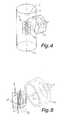
- FIG. 5 show a further embodiment in which the electrodes 7b are formed as arranged radially with respect to the flow axis 1a of the chimney 1 plates, wherein the plates are connected via a comprehensive annular conductor 20 and a rod-shaped conductor 21 to the high voltage generator 13.
- it is for a possible unhindered Flue gas outlet advantageous if the center axes of the inner tube 9, the ionization chamber 6 and the insertion tube 8 are aligned with the flow axis 1 a of the chimney 1.
Landscapes
- Electrostatic Separation (AREA)
Applications Claiming Priority (1)
| Application Number | Priority Date | Filing Date | Title |
|---|---|---|---|
| AT14392007A AT504902B1 (de) | 2007-09-13 | 2007-09-13 | Elektrofilter für eine feuerungsanlage |
Publications (2)
| Publication Number | Publication Date |
|---|---|
| EP2036615A2 true EP2036615A2 (fr) | 2009-03-18 |
| EP2036615A3 EP2036615A3 (fr) | 2010-02-17 |
Family
ID=39735859
Family Applications (1)
| Application Number | Title | Priority Date | Filing Date |
|---|---|---|---|
| EP08162942A Withdrawn EP2036615A3 (fr) | 2007-09-13 | 2008-08-26 | Electrofiltre pour une installation d'allumage |
Country Status (2)
| Country | Link |
|---|---|
| EP (1) | EP2036615A3 (fr) |
| AT (1) | AT504902B1 (fr) |
Cited By (5)
| Publication number | Priority date | Publication date | Assignee | Title |
|---|---|---|---|---|
| CN104566691A (zh) * | 2014-09-30 | 2015-04-29 | 广东美的制冷设备有限公司 | 绝缘卡扣组件及具有其的集尘组件 |
| CN104959231A (zh) * | 2015-06-30 | 2015-10-07 | 成都市新都区鑫悦空气净化设备厂 | 一种高压静电油烟净化装置 |
| KR20170077124A (ko) * | 2014-09-30 | 2017-07-05 | 지디 미디어 에어콘디셔닝 이큅먼트 씨오 엘티디 | 집진 어셈블리, 공기 정화 장치 및 에어컨 |
| KR20170077121A (ko) * | 2014-09-30 | 2017-07-05 | 지디 미디어 에어콘디셔닝 이큅먼트 씨오 엘티디 | 집진 어셈블리, 공기 정화 장치 및 에어컨 |
| IT202200015019A1 (it) * | 2022-07-18 | 2024-01-18 | Masco Eng Group S R L | Sistema di abbattimento del particolato presente nei fumi prodotti da ciminiere |
Families Citing this family (1)
| Publication number | Priority date | Publication date | Assignee | Title |
|---|---|---|---|---|
| CN104613563B (zh) * | 2014-09-30 | 2022-04-12 | 广东美的制冷设备有限公司 | 集尘组件、空气净化装置以及空调器 |
Citations (5)
| Publication number | Priority date | Publication date | Assignee | Title |
|---|---|---|---|---|
| WO1993016807A1 (fr) | 1992-02-20 | 1993-09-02 | Tl-Vent Ab | Filtre electrostatique a deux etages |
| WO2000033945A1 (fr) | 1998-12-04 | 2000-06-15 | Applied Plasma Physics As | Procede et dispositif de nettoyages d'effluents |
| WO2006015504A1 (fr) | 2004-08-11 | 2006-02-16 | Eidgenössische Materialprüfungs- und Forschungsanstalt Empa | Electrofiltre pour installation de combustion |
| WO2006015503A1 (fr) | 2004-08-11 | 2006-02-16 | Eidgenössische Materialprüfungs- und Forschungsanstalt Empa | Electrofiltre pour installation de combustion |
| DE202006016244U1 (de) * | 2006-10-24 | 2007-04-19 | Vitek, Christian, Dipl.-Ing. (FH) | Elektrostatische Reinigungsvorrichtung für die Rauchgase einer Feuerungsanlage |
Family Cites Families (7)
| Publication number | Priority date | Publication date | Assignee | Title |
|---|---|---|---|---|
| GB1239712A (fr) * | 1969-02-13 | 1971-07-21 | ||
| EP0044361A1 (fr) * | 1980-07-18 | 1982-01-27 | Santek Inc. | Précipitateur électrostatique comprenant une structure d'électrode de décharge |
| AT408846B (de) * | 1999-05-03 | 2002-03-25 | Forsthuber Paul | Röhrenelektrofilter |
| US6717792B2 (en) * | 2000-12-08 | 2004-04-06 | Illinois Tool Works Inc. | Emitter assembly |
| US6902604B2 (en) * | 2003-05-15 | 2005-06-07 | Fleetguard, Inc. | Electrostatic precipitator with internal power supply |
| EP1928608A4 (fr) * | 2005-09-29 | 2011-06-01 | Sarnoff Corp | Circuit ballast pour systemes a recueillir les particules electrostatiques |
| DE102006003028B4 (de) * | 2006-01-20 | 2008-02-07 | Schmatloch Nückel Technologietransfer | Elektrofilter mit Selbstreinigungseinrichtung für eine Feuerungsanlage und Verfahren zum Betreiben des Elektrofilters |
-
2007
- 2007-09-13 AT AT14392007A patent/AT504902B1/de not_active IP Right Cessation
-
2008
- 2008-08-26 EP EP08162942A patent/EP2036615A3/fr not_active Withdrawn
Patent Citations (5)
| Publication number | Priority date | Publication date | Assignee | Title |
|---|---|---|---|---|
| WO1993016807A1 (fr) | 1992-02-20 | 1993-09-02 | Tl-Vent Ab | Filtre electrostatique a deux etages |
| WO2000033945A1 (fr) | 1998-12-04 | 2000-06-15 | Applied Plasma Physics As | Procede et dispositif de nettoyages d'effluents |
| WO2006015504A1 (fr) | 2004-08-11 | 2006-02-16 | Eidgenössische Materialprüfungs- und Forschungsanstalt Empa | Electrofiltre pour installation de combustion |
| WO2006015503A1 (fr) | 2004-08-11 | 2006-02-16 | Eidgenössische Materialprüfungs- und Forschungsanstalt Empa | Electrofiltre pour installation de combustion |
| DE202006016244U1 (de) * | 2006-10-24 | 2007-04-19 | Vitek, Christian, Dipl.-Ing. (FH) | Elektrostatische Reinigungsvorrichtung für die Rauchgase einer Feuerungsanlage |
Cited By (10)
| Publication number | Priority date | Publication date | Assignee | Title |
|---|---|---|---|---|
| CN104566691A (zh) * | 2014-09-30 | 2015-04-29 | 广东美的制冷设备有限公司 | 绝缘卡扣组件及具有其的集尘组件 |
| KR20170077124A (ko) * | 2014-09-30 | 2017-07-05 | 지디 미디어 에어콘디셔닝 이큅먼트 씨오 엘티디 | 집진 어셈블리, 공기 정화 장치 및 에어컨 |
| KR20170077121A (ko) * | 2014-09-30 | 2017-07-05 | 지디 미디어 에어콘디셔닝 이큅먼트 씨오 엘티디 | 집진 어셈블리, 공기 정화 장치 및 에어컨 |
| JP2017535411A (ja) * | 2014-09-30 | 2017-11-30 | ジーディー マイディア エア−コンディショニング エクイプメント カンパニー リミテッド | 集塵ユニット、空気清浄化装置及び空気調和器 |
| EP3202500A4 (fr) * | 2014-09-30 | 2018-05-23 | GD Midea Air-Conditioning Equipment Co., Ltd. | Ensemble de collecte de poussière, dispositif de purification d'air et climatiseur |
| EP3202499A4 (fr) * | 2014-09-30 | 2018-05-23 | GD Midea Air-Conditioning Equipment Co., Ltd. | Ensemble dépoussiéreur, dispositif de purification d'air et climatiseur |
| US10272444B2 (en) | 2014-09-30 | 2019-04-30 | Gd Midea Air-Conditioning Equipment Co., Ltd. | Dust collection assembly, air purification device and air conditioner |
| CN104566691B (zh) * | 2014-09-30 | 2022-02-25 | 广东美的制冷设备有限公司 | 绝缘卡扣组件及具有其的集尘组件 |
| CN104959231A (zh) * | 2015-06-30 | 2015-10-07 | 成都市新都区鑫悦空气净化设备厂 | 一种高压静电油烟净化装置 |
| IT202200015019A1 (it) * | 2022-07-18 | 2024-01-18 | Masco Eng Group S R L | Sistema di abbattimento del particolato presente nei fumi prodotti da ciminiere |
Also Published As
| Publication number | Publication date |
|---|---|
| AT504902B1 (de) | 2008-09-15 |
| EP2036615A3 (fr) | 2010-02-17 |
| AT504902A4 (de) | 2008-09-15 |
Similar Documents
| Publication | Publication Date | Title |
|---|---|---|
| DE102004039118B3 (de) | Elektrofilter für eine Feuerungsanlage | |
| AT504902B1 (de) | Elektrofilter für eine feuerungsanlage | |
| DE102007010973B4 (de) | Elektrofilter für eine Kleinfeuerungsanlage | |
| DE3804779C2 (fr) | ||
| EP1930081B1 (fr) | Séparateur électrostatique optimisé | |
| EP2616646B1 (fr) | Dispositif pour traiter des gaz d'échappement contenant des particules de suie | |
| DE102004039124B4 (de) | Elektrofilter für eine Feuerungsanlage | |
| CH675895A5 (fr) | ||
| WO2022069586A1 (fr) | Séparateur électrostatique, section de tube et système produisant une matière particulaire | |
| AT506397B1 (de) | Abscheideeinrichtung für partikel | |
| EP0824376B1 (fr) | Separateur a cyclone muni d'une electrode d'emission | |
| CH702125B1 (de) | Elektrostatischer Feinstaubfilter. | |
| EP0715894B1 (fr) | Installation de filtrage électrostatique | |
| DE102009036957A1 (de) | Elektrostatischer Abscheider und Heizungssystem | |
| EP2266702B1 (fr) | Séparateur électrostatique destiné au nettoyage de gaz de fumée avec un champ de verrouillage électrique | |
| EP2621636B1 (fr) | Étage collecteur d'un séparateur électrostatique pour la purification de gaz de fumée formés par des procédés de combustion | |
| CH623240A5 (fr) | ||
| EP3025785B1 (fr) | Dispositif et procédé de nettoyage de gaz de fumée d'une installation métallurgique | |
| WO2023052137A1 (fr) | Dispositif de purification de gaz de fumée | |
| EP2820258B1 (fr) | Dispositif pour traiter un flux gazeux s'écoulant radialement vers l'extérieur d'une zone centrale | |
| DE102007028134B3 (de) | Elektrostatischer Abscheider und Heizungssystem | |
| EP4000738B1 (fr) | Filtre de nettoyage d'un flux gazeux | |
| CH621492A5 (en) | Gas ioniser for an electrostatic precipitator | |
| DE2809900C2 (de) | Elektroabscheider für die Abgase von Kohlenfeuerungen | |
| DE202005012579U1 (de) | Elektrofilter zum Abscheiden von Partikeln aus einem Gasstrom |
Legal Events
| Date | Code | Title | Description |
|---|---|---|---|
| PUAI | Public reference made under article 153(3) epc to a published international application that has entered the european phase |
Free format text: ORIGINAL CODE: 0009012 |
|
| AK | Designated contracting states |
Kind code of ref document: A2 Designated state(s): AT BE BG CH CY CZ DE DK EE ES FI FR GB GR HR HU IE IS IT LI LT LU LV MC MT NL NO PL PT RO SE SI SK TR |
|
| AX | Request for extension of the european patent |
Extension state: AL BA MK RS |
|
| PUAL | Search report despatched |
Free format text: ORIGINAL CODE: 0009013 |
|
| AK | Designated contracting states |
Kind code of ref document: A3 Designated state(s): AT BE BG CH CY CZ DE DK EE ES FI FR GB GR HR HU IE IS IT LI LT LU LV MC MT NL NO PL PT RO SE SI SK TR |
|
| AX | Request for extension of the european patent |
Extension state: AL BA MK RS |
|
| RIC1 | Information provided on ipc code assigned before grant |
Ipc: B03C 3/08 20060101ALI20100112BHEP Ipc: B03C 3/86 20060101ALI20100112BHEP Ipc: B03C 3/41 20060101AFI20081001BHEP |
|
| 17P | Request for examination filed |
Effective date: 20100806 |
|
| AKX | Designation fees paid |
Designated state(s): AT BE BG CH CY CZ DE DK EE ES FI FR GB GR HR HU IE IS IT LI LT LU LV MC MT NL NO PL PT RO SE SI SK TR |
|
| 17Q | First examination report despatched |
Effective date: 20120111 |
|
| RIN1 | Information on inventor provided before grant (corrected) |
Inventor name: ZELLER, OLIVER Inventor name: BUCHTA, PETER |
|
| RIN1 | Information on inventor provided before grant (corrected) |
Inventor name: DIE ANDERE ERFINDER HABEN AUF IHRE NENNUNG VERZICH Inventor name: ZELLER, OLIVER Inventor name: BUCHTA, PETER |
|
| RIN1 | Information on inventor provided before grant (corrected) |
Inventor name: ZELLER, OLIVER Inventor name: BUCHTA, PETER Inventor name: LEBINGER, PETER |
|
| STAA | Information on the status of an ep patent application or granted ep patent |
Free format text: STATUS: THE APPLICATION IS DEEMED TO BE WITHDRAWN |
|
| 18D | Application deemed to be withdrawn |
Effective date: 20150303 |