EP2036632B1 - Matrice à forger et procédé - Google Patents
Matrice à forger et procédé Download PDFInfo
- Publication number
- EP2036632B1 EP2036632B1 EP08164009.6A EP08164009A EP2036632B1 EP 2036632 B1 EP2036632 B1 EP 2036632B1 EP 08164009 A EP08164009 A EP 08164009A EP 2036632 B1 EP2036632 B1 EP 2036632B1
- Authority
- EP
- European Patent Office
- Prior art keywords
- backplate
- segments
- radial
- forging die
- forging
- Prior art date
- Legal status (The legal status is an assumption and is not a legal conclusion. Google has not performed a legal analysis and makes no representation as to the accuracy of the status listed.)
- Active
Links
Images
Classifications
-
- B—PERFORMING OPERATIONS; TRANSPORTING
- B21—MECHANICAL METAL-WORKING WITHOUT ESSENTIALLY REMOVING MATERIAL; PUNCHING METAL
- B21J—FORGING; HAMMERING; PRESSING METAL; RIVETING; FORGE FURNACES
- B21J13/00—Details of machines for forging, pressing, or hammering
- B21J13/02—Dies or mountings therefor
- B21J13/025—Dies with parts moving along auxiliary lateral directions
-
- B—PERFORMING OPERATIONS; TRANSPORTING
- B21—MECHANICAL METAL-WORKING WITHOUT ESSENTIALLY REMOVING MATERIAL; PUNCHING METAL
- B21J—FORGING; HAMMERING; PRESSING METAL; RIVETING; FORGE FURNACES
- B21J5/00—Methods for forging, hammering, or pressing; Special equipment or accessories therefor
Definitions
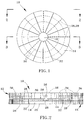
- the present invention generally relates to forging equipment and processes, including those used in the production of large forgings from metal powders. More particularly, this invention relates to a forging die equipped with radial segments that reduce the incidence of cracking during forging of powder metallurgy billets by promoting radial growth during forging.
- Rotor components for power generation turbines have typically been formed of iron and nickel-based alloys with low alloy content, i.e., three or four primary elements, which permit their melting and processing with relative ease and minimal chemical or microstructural segregation.
- wheels, spacers, and other rotor components of more advanced land-based gas turbine engines used in the power-generating industry such as the H and FB class gas turbines of the assignee of this invention, have been formed from high strength alloys such as gamma double-prime ( ⁇ ") precipitation-strengthened nickel-based superalloys, including Alloy 718 and Alloy 706.
- the billet 40 can then be forged with the die 10 of this invention according to known procedures, such as those currently utilized to produce disk forgings for large industrial turbines, though possibly modified to take advantage of the radial movement of the segments 14 during each forging stage, as well as any adjustments to the size of the die 10 made possible by the concentric bands 34 of the backplate 12.
- the forging operation is preferably performed at temperatures and under loading conditions that allow complete filling of the finish forging die cavity, avoid fracture, and produce or retain a uniform desired grain size within the material.
- forging is typically performed under superplastic forming conditions to enable filling of the forging die cavity through the accumulation of high geometric strains.
Landscapes
- Engineering & Computer Science (AREA)
- Mechanical Engineering (AREA)
- Forging (AREA)
- Turbine Rotor Nozzle Sealing (AREA)
- Powder Metallurgy (AREA)
Claims (12)
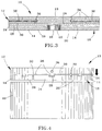
- Matrice à forger (10) comprenant :une pluralité de segments (14) aménagés selon un motif radial autour d'une région (16) sur une première surface (24) d'une plaque d'appui (12), chacun des segments (14) ayant une face arrière en regard de la plaque d'appui (12) et définissant une surface d'interface (18) opposée à la plaque d'appui (12), la surface d'interface (18) étant à même de s'engager sur une billette (40) au cours du forgeage de la billette par la matrice à forger (10) ; etdes moyens (26) pour coupler physiquement les segments (14) à la première surface (24) de la plaque d'appui (12) pour permettre un mouvement radial des segments (14) par rapport à la région (16) de la plaque d'appui ;caractérisé en ce que la plaque d'appui (12) comprend la région (16) et une pluralité d'éléments concentriques (34) qui entourent la région (16) et sont couplés de manière libérable l'un à l'autre, les éléments concentriques (34) définissant la première surface (24) de la plaque d'appui (12).
- Matrice à forger selon la revendication 1, dans laquelle les moyens de couplage (26) comprennent, pour chacun des segments (14), une première caractéristique de guidage radial (26) sur la première surface (24) de la plaque d'appui et une seconde caractéristique de guidage radial complémentaire (28) sur le côté d'appui du segment (14).
- Matrice à forger selon la revendication 2, dans laquelle chacune des premières caractéristiques de guidage radial (26) est une caractéristique de surface exhaussé sur la première surface (24) de la plaque d'appui (12) et chacune des secondes caractéristiques de guidage radial (28) est une rainure sur le côté d'appui du segment (14), les rainures (28) s'emboîtant sur les caractéristiques de surface exhaussées (26) pour permettre un mouvement radial des segments (14) sur la plaque d'appui (12) et empêcher le désaccouplement des segments (14) de la plaque d'appui (12) dans une direction normale à la première surface (24) de la plaque d'appui (12).
- Machine à forger selon l'une quelconque des revendications précédentes, dans laquelle la région autour de laquelle les segments (14) sont aménagés est située centralement sur la plaque d'appui (12).
- Machine à forger selon l'une quelconque des revendications précédentes, dans laquelle tous les segments (14) ont une taille et une forme approximativement égales.
- Machine à forger selon l'une quelconque des revendications précédentes, dans laquelle les segments (14) sont en forme de coin et augmentent en largeur dans la direction radiale en s'écartant de la région de la plaque d'appui (12).
- Machine à forger selon l'une quelconque des revendications précédentes, dans laquelle chacun des segments (14) a des bords radiaux disposés à l'opposé et les segments (14) sont aménagés sur la plaque d'appui (12) de sorte que les bords radiaux de chaque segment (14) soient adjacents aux bords radiaux de segments immédiatement adjacents (14).
- Matrice à forger selon la revendication 7, dans laquelle un intervalle radial (32) est présent entre les bords radiaux adjacents de segments immédiatement adjacents (14).
- Matrice à forger selon l'une quelconque des revendications précédentes, dans laquelle la région de la plaque d'appui (12) définit une surface (22) qui est approximativement de niveau avec des parties immédiatement adjacentes des surfaces d'interface (18) des segments (14).
- Procédé de forgeage comprenant :l'assemblage d'une matrice à forger (10) en aménageant une pluralité de segments (14) selon un motif radial autour d'une région sur une première surface (24) d'une plaque d'appui (12) et en couplant physiquement les segments (14) à la première surface (24) pour permettre un mouvement radial des segments (14) par rapport à la région de la plaque d'appui (12), chacun des segments (14) ayant une face arrière en regard de la plaque d'appui (12) et définissant une surface d'interface (18) à l'opposé de la plaque d'appui (12), la surface d'interface (18) étant à même de s'engager sur une billette (40) au cours du forgeage de la billette (40) par la matrice à forger (10) ; etle forgeage d'une billette (40) avec la matrice à forger (10) en s'engageant sur la billette (40) et en usinant celle-ci avec les surfaces d'interface (18) des segments (14), caractérisé en ce que l'étape d'assemblage comprend en outre l'assemblage de la plaque d'appui (12) par un aménagement concentrique d'une pluralité d'éléments entourant la région, les éléments concentriques définissant la première surface de la plaque d'appui.
- Procédé selon la revendication 10, dans lequel les segments (14) sont couplés à la plaque d'appui (12) afin de permettre un mouvement radial des segments (14) sur la plaque d'appui (12) et empêcher un désaccouplement des segments (14) de la plaque d'appui (12) dans une direction normale à la première surface (24) de la plaque d'appui (12).
- Procédé selon la revendication 10 ou la revendication 11, dans lequel la plaque d'appui (12) est assemblée par couplage des éléments concentriques l'un avec l'autre de manière libérable.
Applications Claiming Priority (1)
| Application Number | Priority Date | Filing Date | Title |
|---|---|---|---|
| US11/856,111 US7805971B2 (en) | 2007-09-17 | 2007-09-17 | Forging die and process |
Publications (3)
| Publication Number | Publication Date |
|---|---|
| EP2036632A2 EP2036632A2 (fr) | 2009-03-18 |
| EP2036632A3 EP2036632A3 (fr) | 2014-11-26 |
| EP2036632B1 true EP2036632B1 (fr) | 2016-06-01 |
Family
ID=40130540
Family Applications (1)
| Application Number | Title | Priority Date | Filing Date |
|---|---|---|---|
| EP08164009.6A Active EP2036632B1 (fr) | 2007-09-17 | 2008-09-10 | Matrice à forger et procédé |
Country Status (4)
| Country | Link |
|---|---|
| US (1) | US7805971B2 (fr) |
| EP (1) | EP2036632B1 (fr) |
| JP (1) | JP5378734B2 (fr) |
| CN (1) | CN101391278B (fr) |
Families Citing this family (17)
| Publication number | Priority date | Publication date | Assignee | Title |
|---|---|---|---|---|
| US8230899B2 (en) * | 2010-02-05 | 2012-07-31 | Ati Properties, Inc. | Systems and methods for forming and processing alloy ingots |
| US9267184B2 (en) | 2010-02-05 | 2016-02-23 | Ati Properties, Inc. | Systems and methods for processing alloy ingots |
| CN101862807B (zh) * | 2010-06-11 | 2012-05-23 | 西安交通大学 | 一种大型盘类件的旋转锻造方法及锻造装置 |
| US10207312B2 (en) | 2010-06-14 | 2019-02-19 | Ati Properties Llc | Lubrication processes for enhanced forgeability |
| US20120051919A1 (en) * | 2010-08-31 | 2012-03-01 | General Electric Company | Powder compact rotor forging preform and forged powder compact turbine rotor and methods of making the same |
| CN102019544B (zh) * | 2010-09-27 | 2012-06-20 | 江阴东大新材料研究院 | 特大型锻件铸焊锻复合成形方法 |
| US8789254B2 (en) | 2011-01-17 | 2014-07-29 | Ati Properties, Inc. | Modifying hot workability of metal alloys via surface coating |
| CN104203450B (zh) * | 2012-03-30 | 2016-05-04 | 日立金属株式会社 | 热锻用模具 |
| US9481932B2 (en) * | 2012-04-26 | 2016-11-01 | Cheung Woh Technologies Ltd. | Method and apparatus for progressively forging a hard disk drive base plate |
| US10245639B2 (en) * | 2012-07-31 | 2019-04-02 | United Technologies Corporation | Powder metallurgy method for making components |
| US9539636B2 (en) | 2013-03-15 | 2017-01-10 | Ati Properties Llc | Articles, systems, and methods for forging alloys |
| US9027374B2 (en) | 2013-03-15 | 2015-05-12 | Ati Properties, Inc. | Methods to improve hot workability of metal alloys |
| DE102014111724B4 (de) * | 2014-08-18 | 2016-03-03 | Kamax Holding Gmbh & Co. Kg | Matrizenmodulsatz für Presswerkzeuge zum Herstellen von Schrauben |
| CN105448308B (zh) | 2014-08-27 | 2019-04-09 | 祥和科技有限公司 | 用于形成具有延长高度的硬盘驱动器基板的方法和装置 |
| US11919065B2 (en) * | 2016-12-21 | 2024-03-05 | Proterial, Ltd. | Method for producing hot-forged material |
| PL443627A1 (pl) * | 2023-01-30 | 2024-08-05 | Schraner Polska Spółka Z Ograniczoną Odpowiedzialnością | Matryce do produkcji precyzyjnych odkuwek małogabarytowych i sposób ich wytwarzania, odkuwka otrzymana tym sposobem |
| CN119387486B (zh) * | 2024-11-12 | 2025-10-03 | 重庆大学 | 一种超大型复杂涡轮盘锻件精密化成形方法及模具 |
Family Cites Families (12)
| Publication number | Priority date | Publication date | Assignee | Title |
|---|---|---|---|---|
| US2754576A (en) * | 1952-01-30 | 1956-07-17 | Kropp Forge Company | Fabrication of forged brake band and the like |
| FR1298452A (fr) * | 1961-05-31 | 1962-07-13 | Commissariat Energie Atomique | Perfectionnements apportés aux procédés et appareils de forgeage à chaud, notamment pour la formation d'une gorge de sertissage |
| JPS5096635U (fr) * | 1974-01-08 | 1975-08-12 | ||
| CH621952A5 (fr) * | 1977-09-01 | 1981-03-13 | Bbc Brown Boveri & Cie | |
| JPS58187221A (ja) * | 1982-04-26 | 1983-11-01 | Daido Steel Co Ltd | 孔あけ装置 |
| JPH0613136B2 (ja) * | 1989-05-18 | 1994-02-23 | 工業技術院長 | セラミックス製恒温鍛造型 |
| JP2723343B2 (ja) * | 1990-06-26 | 1998-03-09 | 株式会社神戸製鋼所 | Ni基超合金製品の恒温鍛造方法 |
| US6484552B1 (en) * | 2000-12-16 | 2002-11-26 | Eaton Aeroquip, Inc. | Hinged die cage assembly |
| US6531002B1 (en) * | 2001-04-24 | 2003-03-11 | General Electric Company | Nickel-base superalloys and articles formed therefrom |
| US6688154B2 (en) * | 2001-07-19 | 2004-02-10 | Showa Denko Kabushiki Kaisha | Die for forging rotor, forge production system and forging method using the die, and rotor |
| DE10318060A1 (de) * | 2003-04-17 | 2004-11-18 | Eckold Gmbh & Co Kg | Matrize für einen Werkzeugsatz zum mechanischen Fügen |
| CN100361762C (zh) * | 2005-07-29 | 2008-01-16 | 中国科学院金属研究所 | 一种镁合金手机外壳的温热成形方法 |
-
2007
- 2007-09-17 US US11/856,111 patent/US7805971B2/en active Active
-
2008
- 2008-09-10 EP EP08164009.6A patent/EP2036632B1/fr active Active
- 2008-09-12 JP JP2008234141A patent/JP5378734B2/ja active Active
- 2008-09-17 CN CN200810168006.4A patent/CN101391278B/zh not_active Expired - Fee Related
Non-Patent Citations (1)
| Title |
|---|
| None * |
Also Published As
| Publication number | Publication date |
|---|---|
| CN101391278B (zh) | 2013-07-31 |
| US20090133462A1 (en) | 2009-05-28 |
| EP2036632A2 (fr) | 2009-03-18 |
| EP2036632A3 (fr) | 2014-11-26 |
| CN101391278A (zh) | 2009-03-25 |
| JP5378734B2 (ja) | 2013-12-25 |
| JP2009066661A (ja) | 2009-04-02 |
| US7805971B2 (en) | 2010-10-05 |
Similar Documents
| Publication | Publication Date | Title |
|---|---|---|
| EP2036632B1 (fr) | Matrice à forger et procédé | |
| JP5780728B2 (ja) | 多元合金ローターセクション、それを含む溶接されたタービンローター及びその製造方法 | |
| US6240765B1 (en) | Closed-die forging process and rotationally incremental forging press | |
| EP0171344B1 (fr) | Procédé pour la fabrication d'un rotor avec pales intégrées | |
| US5113583A (en) | Integrally bladed rotor fabrication | |
| US4536932A (en) | Method for eliminating low cycle fatigue cracking in integrally bladed disks | |
| CN105170853B (zh) | 超大型空心盘形锻件的整锻成形方法 | |
| EP2353750B1 (fr) | Procédé de soudage et forgeage pour produire un composant | |
| EP3682982A1 (fr) | Procédé de fabrication pour une pièce forgée annulaire de grandes dimensions | |
| EP2520395A2 (fr) | Composants et procédés de production de composants avec des régions ayant différentes structures de grain | |
| US20130156558A1 (en) | Annular gas turbine engine case and method of manufacturing | |
| JP2006017125A (ja) | 回転機械を製作するための方法及び装置 | |
| CN105050749A (zh) | 环轧用材料的制造方法 | |
| JP2011255409A (ja) | 環状成形体の製造方法 | |
| CA2603503C (fr) | Carter annulaire pour moteur a turbine a gaz et methode de fabrication connexe | |
| CA2602994C (fr) | Carter annulaire pour moteur a turbine a gaz et methode de fabrication connexe | |
| JP5795838B2 (ja) | リング状成形体の製造方法 | |
| JP2558858B2 (ja) | 中空部材の鍛造装置及びその方法 | |
| US3866303A (en) | Method of making cross-rolled powder metal discs | |
| EP0846505A2 (fr) | Procédé de forgeage en matrices fermées et presse à forger rotative | |
| CA2602981A1 (fr) | Carter annulaire pour moteur a turbine a gaz et methode de fabrication connexe | |
| CN113458308A (zh) | 一种实现超大型涡轮盘锻件的极限成形方法 | |
| JP6410135B2 (ja) | 熱間鍛造用金型 | |
| Wright et al. | Forging of blades for gas turbines | |
| US8177516B2 (en) | Shaped rotor wheel capable of carrying multiple blade stages |
Legal Events
| Date | Code | Title | Description |
|---|---|---|---|
| PUAI | Public reference made under article 153(3) epc to a published international application that has entered the european phase |
Free format text: ORIGINAL CODE: 0009012 |
|
| AK | Designated contracting states |
Kind code of ref document: A2 Designated state(s): AT BE BG CH CY CZ DE DK EE ES FI FR GB GR HR HU IE IS IT LI LT LU LV MC MT NL NO PL PT RO SE SI SK TR |
|
| AX | Request for extension of the european patent |
Extension state: AL BA MK RS |
|
| PUAL | Search report despatched |
Free format text: ORIGINAL CODE: 0009013 |
|
| AK | Designated contracting states |
Kind code of ref document: A3 Designated state(s): AT BE BG CH CY CZ DE DK EE ES FI FR GB GR HR HU IE IS IT LI LT LU LV MC MT NL NO PL PT RO SE SI SK TR |
|
| AX | Request for extension of the european patent |
Extension state: AL BA MK RS |
|
| RIC1 | Information provided on ipc code assigned before grant |
Ipc: B21J 13/02 20060101ALI20141017BHEP Ipc: B21J 5/00 20060101AFI20141017BHEP |
|
| 17P | Request for examination filed |
Effective date: 20150526 |
|
| RBV | Designated contracting states (corrected) |
Designated state(s): AT BE BG CH CY CZ DE DK EE ES FI FR GB GR HR HU IE IS IT LI LT LU LV MC MT NL NO PL PT RO SE SI SK TR |
|
| AKX | Designation fees paid |
Designated state(s): CH DE FR GB LI |
|
| AXX | Extension fees paid |
Extension state: MK Extension state: RS Extension state: AL Extension state: BA |
|
| GRAP | Despatch of communication of intention to grant a patent |
Free format text: ORIGINAL CODE: EPIDOSNIGR1 |
|
| INTG | Intention to grant announced |
Effective date: 20160225 |
|
| GRAS | Grant fee paid |
Free format text: ORIGINAL CODE: EPIDOSNIGR3 |
|
| GRAA | (expected) grant |
Free format text: ORIGINAL CODE: 0009210 |
|
| AK | Designated contracting states |
Kind code of ref document: B1 Designated state(s): CH DE FR GB LI |
|
| REG | Reference to a national code |
Ref country code: GB Ref legal event code: FG4D |
|
| REG | Reference to a national code |
Ref country code: CH Ref legal event code: EP |
|
| REG | Reference to a national code |
Ref country code: DE Ref legal event code: R096 Ref document number: 602008044505 Country of ref document: DE |
|
| REG | Reference to a national code |
Ref country code: FR Ref legal event code: PLFP Year of fee payment: 9 |
|
| REG | Reference to a national code |
Ref country code: DE Ref legal event code: R097 Ref document number: 602008044505 Country of ref document: DE |
|
| PLBE | No opposition filed within time limit |
Free format text: ORIGINAL CODE: 0009261 |
|
| STAA | Information on the status of an ep patent application or granted ep patent |
Free format text: STATUS: NO OPPOSITION FILED WITHIN TIME LIMIT |
|
| 26N | No opposition filed |
Effective date: 20170302 |
|
| REG | Reference to a national code |
Ref country code: FR Ref legal event code: PLFP Year of fee payment: 10 |
|
| REG | Reference to a national code |
Ref country code: FR Ref legal event code: PLFP Year of fee payment: 11 |
|
| PGFP | Annual fee paid to national office [announced via postgrant information from national office to epo] |
Ref country code: GB Payment date: 20210820 Year of fee payment: 14 Ref country code: CH Payment date: 20210818 Year of fee payment: 14 Ref country code: DE Payment date: 20210818 Year of fee payment: 14 |
|
| REG | Reference to a national code |
Ref country code: DE Ref legal event code: R119 Ref document number: 602008044505 Country of ref document: DE |
|
| REG | Reference to a national code |
Ref country code: CH Ref legal event code: PL |
|
| GBPC | Gb: european patent ceased through non-payment of renewal fee |
Effective date: 20220910 |
|
| PG25 | Lapsed in a contracting state [announced via postgrant information from national office to epo] |
Ref country code: LI Free format text: LAPSE BECAUSE OF NON-PAYMENT OF DUE FEES Effective date: 20220930 Ref country code: DE Free format text: LAPSE BECAUSE OF NON-PAYMENT OF DUE FEES Effective date: 20230401 Ref country code: CH Free format text: LAPSE BECAUSE OF NON-PAYMENT OF DUE FEES Effective date: 20220930 |
|
| PG25 | Lapsed in a contracting state [announced via postgrant information from national office to epo] |
Ref country code: GB Free format text: LAPSE BECAUSE OF NON-PAYMENT OF DUE FEES Effective date: 20220910 |
|
| PGFP | Annual fee paid to national office [announced via postgrant information from national office to epo] |
Ref country code: FR Payment date: 20250821 Year of fee payment: 18 |