EP2036633A1 - Punch and recessed screw formed thereby - Google Patents
Punch and recessed screw formed thereby Download PDFInfo
- Publication number
- EP2036633A1 EP2036633A1 EP07116448A EP07116448A EP2036633A1 EP 2036633 A1 EP2036633 A1 EP 2036633A1 EP 07116448 A EP07116448 A EP 07116448A EP 07116448 A EP07116448 A EP 07116448A EP 2036633 A1 EP2036633 A1 EP 2036633A1
- Authority
- EP
- European Patent Office
- Prior art keywords
- punch
- square
- square portion
- screw
- socket
- Prior art date
- Legal status (The legal status is an assumption and is not a legal conclusion. Google has not performed a legal analysis and makes no representation as to the accuracy of the status listed.)
- Withdrawn
Links
- 238000004080 punching Methods 0.000 abstract description 7
- 230000009977 dual effect Effects 0.000 description 6
- 230000001737 promoting effect Effects 0.000 description 2
- 230000015572 biosynthetic process Effects 0.000 description 1
- 230000007547 defect Effects 0.000 description 1
Images



Classifications
-
- B—PERFORMING OPERATIONS; TRANSPORTING
- B21—MECHANICAL METAL-WORKING WITHOUT ESSENTIALLY REMOVING MATERIAL; PUNCHING METAL
- B21K—MAKING FORGED OR PRESSED METAL PRODUCTS, e.g. HORSE-SHOES, RIVETS, BOLTS OR WHEELS
- B21K1/00—Making machine elements
- B21K1/44—Making machine elements bolts, studs, or the like
- B21K1/46—Making machine elements bolts, studs, or the like with heads
- B21K1/463—Making machine elements bolts, studs, or the like with heads with recessed heads
-
- F—MECHANICAL ENGINEERING; LIGHTING; HEATING; WEAPONS; BLASTING
- F16—ENGINEERING ELEMENTS AND UNITS; GENERAL MEASURES FOR PRODUCING AND MAINTAINING EFFECTIVE FUNCTIONING OF MACHINES OR INSTALLATIONS; THERMAL INSULATION IN GENERAL
- F16B—DEVICES FOR FASTENING OR SECURING CONSTRUCTIONAL ELEMENTS OR MACHINE PARTS TOGETHER, e.g. NAILS, BOLTS, CIRCLIPS, CLAMPS, CLIPS OR WEDGES; JOINTS OR JOINTING
- F16B23/00—Specially shaped nuts or heads of bolts or screws for rotations by a tool
- F16B23/0061—Specially shaped nuts or heads of bolts or screws for rotations by a tool with grooves, notches or splines on the external peripheral surface designed for tools engaging in radial direction
Definitions
- the present invention relates to a punch and a recessed screw according to the preamble to claim 1.
- the present invention concerns with a punch including dual tiers of square portions for punching the corresponding tiers of recesses in the screw head, which is conducive to receive a screwdriver presenting a square shape or a configuration as the same as the punch.
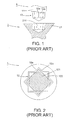
- a conventional punch 1 of the U. S. Patent No. 3972083 discloses a punch body 11 and a punch head 12 extended from the punch body 11 for punching a recess 211 in a screw head 21 of a screw 2; wherein, the punch head 12 presents in cross section eight symmetrically corners defined by any of two adjacent wall portions 12a and 12b, which intersect at a right angle as shown in Fig. 2 . Any series of four alternate corners defines a square 121 in solid line and cross hatched, and the remaining series of four alternate corners defines another square 122 in dotted line.
- the punch shank 12 While in punching, the punch shank 12 is set into the recess 211, which is formed by a single punch blow at room temperature and has a configuration corresponding to the punch 1 for the entrance of a square screwdriver.
- the recess 211 punched by the punch 1 receives the square screwdriver, there may be some defects. Due to the configuration of the punch head 12, a single tier of the recess 211 is accordingly formed, which may merely receive a simple square screwdriver, but may not be optimally seated by a square screwdriver with different dimensions. As a result, it may bring the inconvenience for the users while in operation.
- the objects of the present invention are to provide a punch for punching a socket in a screw head, where dual tiers of the recesses are formed in accordance with the configurations of the square portions of the punch, thus improving the problem of unfitted driving tool and increase the convenience while using.
- the punch for forming recessed screw related to the present invention comprises a punch body and a punch head; wherein, the punch body has a first square portion and a second square portion being in an included angle relation thereto; the height of the second square portion extended from the punch body exceeds that of the first square portion, and each of the series of square sides of the first square portion is greater than that of the second square portion, so as to form dual tiers of recesses in the socket of the screw head, which facilitates to decrease the problem of unfitted driving tool and increase the convenience in use.
- a punch 3 for forming recessed screw 4 of the preferred embodiment of the present invention comprises a punch body 31 and a punch head 32 longitudinally extended from the punch body 31; characterized in that the punch body 31 comprises a first square portion 321 and a second square portion 322 disposed on the first square portion 321; the first square portion 321 is inclined with respect to the second square portion 322 by an included angle " ⁇ ", which is in 45 degrees and is adopted in the preferred embodiment of the present invention.
- Both of the square portions 321 and 322 have heights "x" and "y” extended from the punch body 31 and have two series of square sides “a” and "b” defined around the peripheries thereof, respectively.
- the height " y " of the second square portion 322 exceeds the height "x" of the first square portion 321; moreover, each of the series of square sides “a” of the first square portion 321 is greater than each of the series of square sides "b” of the second square portion 322.
- the recessed screw 4 punched by the punch 3 comprises a screw head 41, a shank 42 longitudinally extended from the screw head 41, and a plurality of threads 43 built upon an outer circumference of the shank 42; wherein, a socket 411 is punched in the screw head 41 by the punch 3 for receiving a screwdriver; the socket 411 consists of a first recess 412 and a second recess 413; further, the first recess 412 and the second recess 413 separately have two series of square sides "c" and "d” defined around the peripheries thereof, which are in different widths.
- each of the series of square sides "c" of the first recess 412 equals to each of the series of square sides "a” of the first square portion 321
- each of the series of square sides "d” of the second recess 413 equals to each of the series of square sides "b" of the second square portion 322
- the punch 3 initially punches a socket 411 in the screw head 41 of the screw 4, and the first recess 412 and the second recess 413 are accordingly formed in the socket 411 in accordance to the configuration of the first square portion 321 and the second square portion 322.
- the first square portion 321 comprises the larger series of square sides "a” and the shorter height "x" than those of the second square portion 322 and is inclined with respect to the second square portion 322 by the included angle " ⁇ ”
- dual tiers of recesses 412 and 413 are accordingly formed in the socket 411 with different series of square sides "c" and "d”.
- a plurality of threads 43 is formed on the outer circumference of the shank 42, and further an integral recessed screw 4 is presented in Fig. 3
- the screwdrivers 5 and 6 with various configurations can fit with the socket 411. That is, the screwdrivers 5 and 6 as shown in sequence in Fig. 6 , Fig. 7 , and Fig. 8 alternatively provide with the shapes corresponding to the shape of the first recess 412, of the second recess 413, or of the configuration of the square portions 321 and 322, so as to accurately fit with the different dimensions of the socket 411 to drive the screw 4.
- the screwdriver 5 is initially arranged as a square shape in conformity of the shape of the first recess 412, which results in the screwdriver 5 to be facilely and accurately drive into the first recess 412 of the socket 411.
- the screwdriver 5 as illustrated in Fig. 7 presents a square shape in conformity of the shape of the second recess 413, thus improving the problem of the inadequate screwdriver 5 and increase the convenience while screwing.
- the screwdriver 6 comprises a uniform shape as the configurations of the first square portions 321 and the second square portion 322, and the screwdriver 6 thus entirely and accurately fits with the socket 411, which facilitates to transfer a force on the screw 4 and prevent the screwdriver 6 from being facilely out of the socket 411 while driving the screw 4.
- the present invention notably takes advantage of the square portions of the punch for punching a socket in the screw head, which results in forming dual tiers of the recess with different dimensions therein.
- the recessed screw receives a screwdriver presenting a square shape or a configuration as the same as the punch head, thereby reducing the problem of unfitted driving tool and increasing the convenience of the operation.
Landscapes
- Engineering & Computer Science (AREA)
- Mechanical Engineering (AREA)
- General Engineering & Computer Science (AREA)
- Punching Or Piercing (AREA)
Abstract
The present invention pertains to a punch (3) for forming recessed screw (4) comprising a punch body (31) and a punch head (32). Particularly, the punch head includes two square portions (321, 322) having different heights (x, y) and square sides (a, b) and intersecting at an included angle (θ), thereby punching the corresponding tiers of recesses (412, 413) in the socket (411) of the screw head (41). In this manner, the screw can be facilely driven by a screwdriver (5, 6) presenting a square configuration or a uniform shape as the punch, which facilitates to reduce the problem of unfitted driving tool and increase the convenience while in operation.
Description
- The present invention relates to a punch and a recessed screw according to the preamble to claim 1. The present invention concerns with a punch including dual tiers of square portions for punching the corresponding tiers of recesses in the screw head, which is conducive to receive a screwdriver presenting a square shape or a configuration as the same as the punch.
- Referring to
Fig. 1 and 2 , aconventional punch 1 of theU. S. Patent No. 3972083 discloses apunch body 11 and apunch head 12 extended from thepunch body 11 for punching arecess 211 in ascrew head 21 of ascrew 2; wherein, thepunch head 12 presents in cross section eight symmetrically corners defined by any of twoadjacent wall portions Fig. 2 . Any series of four alternate corners defines asquare 121 in solid line and cross hatched, and the remaining series of four alternate corners defines anothersquare 122 in dotted line. - While in punching, the
punch shank 12 is set into therecess 211, which is formed by a single punch blow at room temperature and has a configuration corresponding to thepunch 1 for the entrance of a square screwdriver. - From the above, although the
recess 211 punched by thepunch 1 receives the square screwdriver, there may be some defects. Due to the configuration of thepunch head 12, a single tier of therecess 211 is accordingly formed, which may merely receive a simple square screwdriver, but may not be optimally seated by a square screwdriver with different dimensions. As a result, it may bring the inconvenience for the users while in operation. - Therefore, the objects of the present invention are to provide a punch for punching a socket in a screw head, where dual tiers of the recesses are formed in accordance with the configurations of the square portions of the punch, thus improving the problem of unfitted driving tool and increase the convenience while using.
- The punch for forming recessed screw related to the present invention comprises a punch body and a punch head; wherein, the punch body has a first square portion and a second square portion being in an included angle relation thereto; the height of the second square portion extended from the punch body exceeds that of the first square portion, and each of the series of square sides of the first square portion is greater than that of the second square portion, so as to form dual tiers of recesses in the socket of the screw head, which facilitates to decrease the problem of unfitted driving tool and increase the convenience in use.
- The present invention will become more apparent from the following description when taken in conjunction with the accompanying drawings.
-
- Fig.
- 1 is a schematic view showing a conventional punch of
U. S. Patent No. 3972083 for forming a socket in a screw head; - Fig. 2
- is a schematic view showing the outline in underside plan of the conventional punch of
U.S. Patent No. 3972083 ; - Fig. 3
- is a perspective view showing a punch and a related recessed screw of the preferred embodiment of the present invention;
- Fig. 4
- is a top view showing the formation of the recessed screw punched by the punch of
Fig. 3 ; - Fig. 5
- is a schematic view showing a state of the punching of the preferred embodiment of the present invention that the punch of
Fig. 3 punches a socket in the screw head; - Fig. 6
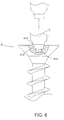
- and 7 are schematic views showing the screwdrivers respectively formed in conformity with the shape of the first square portion and the second square portion of the punch, thereby promoting the screwdriver to accurately fit with the socket of the screw head; and
- Fig. 8
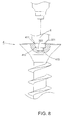
- is a schematic view showing a screwdriver formed in conformity with a configuration of the entire punch head of the punch, thereby promoting the screwdriver to accurately fit with the socket of the screw head.
- Referring to
Fig. 3 , apunch 3 for formingrecessed screw 4 of the preferred embodiment of the present invention comprises apunch body 31 and apunch head 32 longitudinally extended from thepunch body 31; characterized in that thepunch body 31 comprises a firstsquare portion 321 and asecond square portion 322 disposed on the firstsquare portion 321; the firstsquare portion 321 is inclined with respect to the secondsquare portion 322 by an included angle "θ", which is in 45 degrees and is adopted in the preferred embodiment of the present invention. Both of thesquare portions punch body 31 and have two series of square sides "a" and "b" defined around the peripheries thereof, respectively. The height "y" of the secondsquare portion 322 exceeds the height "x" of the firstsquare portion 321; moreover, each of the series of square sides "a" of the firstsquare portion 321 is greater than each of the series of square sides "b" of the secondsquare portion 322. - Further referring to
Fig. 3 and4 , therecessed screw 4 punched by thepunch 3 comprises ascrew head 41, ashank 42 longitudinally extended from thescrew head 41, and a plurality ofthreads 43 built upon an outer circumference of theshank 42; wherein, asocket 411 is punched in thescrew head 41 by thepunch 3 for receiving a screwdriver; thesocket 411 consists of afirst recess 412 and asecond recess 413; further, thefirst recess 412 and thesecond recess 413 separately have two series of square sides "c" and "d" defined around the peripheries thereof, which are in different widths. Since thepunch head 32 punches to thescrew 4, therecesses socket 411 are simultaneous formed in dual tiers corresponding to the configurations of thesquare portions first recess 412 equals to each of the series of square sides "a" of the firstsquare portion 321, and each of the series of square sides "d" of thesecond recess 413 equals to each of the series of square sides "b" of the secondsquare portion 322, - Still further, referring to
Fig. 3 to 5 , thepunch 3 initially punches asocket 411 in thescrew head 41 of thescrew 4, and thefirst recess 412 and thesecond recess 413 are accordingly formed in thesocket 411 in accordance to the configuration of the firstsquare portion 321 and the secondsquare portion 322. According to the configurations that the firstsquare portion 321 comprises the larger series of square sides "a" and the shorter height "x" than those of the secondsquare portion 322 and is inclined with respect to the secondsquare portion 322 by the included angle "θ", thus dual tiers ofrecesses socket 411 with different series of square sides "c" and "d". Subsequently, a plurality ofthreads 43 is formed on the outer circumference of theshank 42, and further an integral recessedscrew 4 is presented inFig. 3 - By means of the different dimensions of the
recess screwdrivers socket 411. That is, thescrewdrivers Fig. 6 ,Fig. 7 , andFig. 8 alternatively provide with the shapes corresponding to the shape of thefirst recess 412, of thesecond recess 413, or of the configuration of thesquare portions socket 411 to drive thescrew 4. - Starting with
Fig. 6 , thescrewdriver 5 is initially arranged as a square shape in conformity of the shape of thefirst recess 412, which results in thescrewdriver 5 to be facilely and accurately drive into thefirst recess 412 of thesocket 411. Similarly, thescrewdriver 5 as illustrated inFig. 7 presents a square shape in conformity of the shape of thesecond recess 413, thus improving the problem of theinadequate screwdriver 5 and increase the convenience while screwing. - Further referring to
Fig. 8 , thescrewdriver 6 comprises a uniform shape as the configurations of the firstsquare portions 321 and the secondsquare portion 322, and thescrewdriver 6 thus entirely and accurately fits with thesocket 411, which facilitates to transfer a force on thescrew 4 and prevent thescrewdriver 6 from being facilely out of thesocket 411 while driving thescrew 4. - To sum up, the present invention notably takes advantage of the square portions of the punch for punching a socket in the screw head, which results in forming dual tiers of the recess with different dimensions therein. Thus, the recessed screw receives a screwdriver presenting a square shape or a configuration as the same as the punch head, thereby reducing the problem of unfitted driving tool and increasing the convenience of the operation.
Claims (3)
- A punch (3) for forming recessed screw (4) comprising:a punch body (31); anda punch head (32) longitudinally extended from said punch body (31) ;wherein, said punch body (31) comprising a first square portion (321) and a second square portion (322) disposed on said first square portion (321), said first square portion (321) being inclined with respect to said second square portion (322) by an included angle (θ); said first and said second square portion(321, 322) having heights (x, y) extended from the punch body (31) and having two series of square sides (a, b) defined around peripheries thereof, respectively; said height (y) of said second square portion (322) exceeding said height (x) of said first square portion (321); each of said series of square sides (a) of said first square portion (321) being greater than each of said series of square sides (b) of said second square portion (322).
- A recessed screw (4) punched by said punch of Claim 1 comprising:a screw head (41);a shank (42) longitudinally extended from said screw head (41) ; anda plurality of threads (43) built on an outer circumference of said shank (42);wherein, a socket (411) being punched by said punch (3) of Claim 1 and defined in said screw head (41); said socket (411) consisting of a first recess (412) and a second recess (413), which are shaped corresponding to the configurations of said first square portion (321) and said second square portion (322).
- The punch (3) for forming recessed screw (4) as claimed in claim 1, wherein said included angle (θ) is in 45 degrees.
Priority Applications (1)
| Application Number | Priority Date | Filing Date | Title |
|---|---|---|---|
| EP07116448A EP2036633A1 (en) | 2007-09-14 | 2007-09-14 | Punch and recessed screw formed thereby |
Applications Claiming Priority (1)
| Application Number | Priority Date | Filing Date | Title |
|---|---|---|---|
| EP07116448A EP2036633A1 (en) | 2007-09-14 | 2007-09-14 | Punch and recessed screw formed thereby |
Publications (1)
| Publication Number | Publication Date |
|---|---|
| EP2036633A1 true EP2036633A1 (en) | 2009-03-18 |
Family
ID=38866435
Family Applications (1)
| Application Number | Title | Priority Date | Filing Date |
|---|---|---|---|
| EP07116448A Withdrawn EP2036633A1 (en) | 2007-09-14 | 2007-09-14 | Punch and recessed screw formed thereby |
Country Status (1)
| Country | Link |
|---|---|
| EP (1) | EP2036633A1 (en) |
Cited By (2)
| Publication number | Priority date | Publication date | Assignee | Title |
|---|---|---|---|---|
| US9987735B2 (en) | 2015-03-16 | 2018-06-05 | Techtronic Industries Co. Ltd. | Nail set |
| CN109079021A (en) * | 2017-06-13 | 2018-12-25 | 鸣达精工股份有限公司 | Die punch for manufacturing fastener |
Citations (6)
| Publication number | Priority date | Publication date | Assignee | Title |
|---|---|---|---|---|
| US3463209A (en) * | 1965-05-17 | 1969-08-26 | Romain Podolsky | Screw fasteners |
| US3888144A (en) * | 1974-02-08 | 1975-06-10 | Joseph D Parsons | Screw and driver |
| US3972083A (en) | 1971-10-31 | 1976-08-03 | P.L. Robertson Manufacturing Co. Ltd. | Punch for making recessed screw |
| DE29719063U1 (en) * | 1997-10-23 | 1998-12-24 | Seeger, Patrick, 74545 Michelfeld | Screw with double screw inner head |
| US20050158148A1 (en) * | 2001-09-17 | 2005-07-21 | Uni-Screw Limited, A United Kingdom Corporation | Screw head formation |
| US20060025225A1 (en) * | 2004-08-02 | 2006-02-02 | Keng-Shui Wu | Screw head slot shaper |
-
2007
- 2007-09-14 EP EP07116448A patent/EP2036633A1/en not_active Withdrawn
Patent Citations (6)
| Publication number | Priority date | Publication date | Assignee | Title |
|---|---|---|---|---|
| US3463209A (en) * | 1965-05-17 | 1969-08-26 | Romain Podolsky | Screw fasteners |
| US3972083A (en) | 1971-10-31 | 1976-08-03 | P.L. Robertson Manufacturing Co. Ltd. | Punch for making recessed screw |
| US3888144A (en) * | 1974-02-08 | 1975-06-10 | Joseph D Parsons | Screw and driver |
| DE29719063U1 (en) * | 1997-10-23 | 1998-12-24 | Seeger, Patrick, 74545 Michelfeld | Screw with double screw inner head |
| US20050158148A1 (en) * | 2001-09-17 | 2005-07-21 | Uni-Screw Limited, A United Kingdom Corporation | Screw head formation |
| US20060025225A1 (en) * | 2004-08-02 | 2006-02-02 | Keng-Shui Wu | Screw head slot shaper |
Cited By (2)
| Publication number | Priority date | Publication date | Assignee | Title |
|---|---|---|---|---|
| US9987735B2 (en) | 2015-03-16 | 2018-06-05 | Techtronic Industries Co. Ltd. | Nail set |
| CN109079021A (en) * | 2017-06-13 | 2018-12-25 | 鸣达精工股份有限公司 | Die punch for manufacturing fastener |
Similar Documents
| Publication | Publication Date | Title |
|---|---|---|
| US11161169B2 (en) | Molds and punches for making fasteners and tools | |
| US5277531A (en) | Device having socket with retention surfaces | |
| EP2734740B1 (en) | Screw head | |
| US9644660B2 (en) | Assembly improving, low mass, fastener head | |
| US7891274B2 (en) | High strength fastener system | |
| US20030059276A1 (en) | Screw socket opening for receiving various tool bits | |
| CA2392892A1 (en) | Wood screw | |
| US7883308B2 (en) | Slotted set screw | |
| US6729208B1 (en) | Tool for removing fasteners | |
| CN102554109A (en) | Method for manufacturing fastening screw and fastening screw | |
| US8757950B2 (en) | Structure of cross-shaped groove of screw for fit with driver bit | |
| US4235149A (en) | Self-thread creating fastener and method and apparatus for making the same | |
| EP2036633A1 (en) | Punch and recessed screw formed thereby | |
| JP2014156898A (en) | Screw with drive hole and header punch for manufacturing screw with drive hole | |
| US20090069103A1 (en) | Punch and related recessed screw | |
| CA2609883C (en) | Punch and related recessed screw | |
| EP3064787B1 (en) | Self-tapping screw and method of manufacturing the same | |
| US20070065253A1 (en) | Fasteners with multi-tiered recesses and drivers with multi-tiered driving tips | |
| US20090311069A1 (en) | Insert nut and insert t-nut | |
| US6406376B1 (en) | Compound screw drive recesses mold | |
| JP2008256124A (en) | Bit engaging hole screw, group of bit engaging hole screw and driver bit combination, and method for setting bit engaging hole shape and dimension | |
| US20220126356A1 (en) | Method for manufacturing a multi-functional fastener | |
| JP2009243689A (en) | Screw with bit engagement hole, combination of groups of screws with bit engagement holes and driver bits, and geometry setting method for bit engagement hole | |
| EP3150867B1 (en) | Recessed head screw | |
| JPH0648166Y2 (en) | nail |
Legal Events
| Date | Code | Title | Description |
|---|---|---|---|
| PUAI | Public reference made under article 153(3) epc to a published international application that has entered the european phase |
Free format text: ORIGINAL CODE: 0009012 |
|
| AK | Designated contracting states |
Kind code of ref document: A1 Designated state(s): AT BE BG CH CY CZ DE DK EE ES FI FR GB GR HU IE IS IT LI LT LU LV MC MT NL PL PT RO SE SI SK TR |
|
| AX | Request for extension of the european patent |
Extension state: AL BA HR MK RS |
|
| AKX | Designation fees paid | ||
| STAA | Information on the status of an ep patent application or granted ep patent |
Free format text: STATUS: THE APPLICATION IS DEEMED TO BE WITHDRAWN |
|
| 18D | Application deemed to be withdrawn |
Effective date: 20090919 |
|
| REG | Reference to a national code |
Ref country code: DE Ref legal event code: 8566 |