EP2036634A1 - Schleudergiessverfahren und Vorrichtung - Google Patents
Schleudergiessverfahren und Vorrichtung Download PDFInfo
- Publication number
- EP2036634A1 EP2036634A1 EP08252676A EP08252676A EP2036634A1 EP 2036634 A1 EP2036634 A1 EP 2036634A1 EP 08252676 A EP08252676 A EP 08252676A EP 08252676 A EP08252676 A EP 08252676A EP 2036634 A1 EP2036634 A1 EP 2036634A1
- Authority
- EP
- European Patent Office
- Prior art keywords
- alloy
- chamber
- mould
- aluminium
- impurity
- Prior art date
- Legal status (The legal status is an assumption and is not a legal conclusion. Google has not performed a legal analysis and makes no representation as to the accuracy of the status listed.)
- Granted
Links
- 238000000034 method Methods 0.000 title claims description 18
- 238000009750 centrifugal casting Methods 0.000 title abstract description 5
- 239000000956 alloy Substances 0.000 claims abstract description 64
- 229910045601 alloy Inorganic materials 0.000 claims abstract description 64
- 239000012535 impurity Substances 0.000 claims abstract description 21
- PNEYBMLMFCGWSK-UHFFFAOYSA-N Alumina Chemical group [O-2].[O-2].[O-2].[Al+3].[Al+3] PNEYBMLMFCGWSK-UHFFFAOYSA-N 0.000 claims description 20
- 229910052782 aluminium Inorganic materials 0.000 claims description 15
- 239000004411 aluminium Substances 0.000 claims description 14
- XAGFODPZIPBFFR-UHFFFAOYSA-N aluminium Chemical compound [Al] XAGFODPZIPBFFR-UHFFFAOYSA-N 0.000 claims description 14
- 239000010936 titanium Substances 0.000 claims description 7
- RTAQQCXQSZGOHL-UHFFFAOYSA-N Titanium Chemical compound [Ti] RTAQQCXQSZGOHL-UHFFFAOYSA-N 0.000 claims description 6
- 239000000470 constituent Substances 0.000 claims description 6
- 229910052719 titanium Inorganic materials 0.000 claims description 6
- 229910052720 vanadium Inorganic materials 0.000 claims description 6
- 229910052804 chromium Inorganic materials 0.000 claims description 5
- 239000011651 chromium Substances 0.000 claims description 5
- LEONUFNNVUYDNQ-UHFFFAOYSA-N vanadium atom Chemical compound [V] LEONUFNNVUYDNQ-UHFFFAOYSA-N 0.000 claims description 5
- VYZAMTAEIAYCRO-UHFFFAOYSA-N Chromium Chemical compound [Cr] VYZAMTAEIAYCRO-UHFFFAOYSA-N 0.000 claims description 4
- GWEVSGVZZGPLCZ-UHFFFAOYSA-N Titan oxide Chemical compound O=[Ti]=O GWEVSGVZZGPLCZ-UHFFFAOYSA-N 0.000 claims 2
- WGLPBDUCMAPZCE-UHFFFAOYSA-N Trioxochromium Chemical compound O=[Cr](=O)=O WGLPBDUCMAPZCE-UHFFFAOYSA-N 0.000 claims 2
- XHCLAFWTIXFWPH-UHFFFAOYSA-N [O-2].[O-2].[O-2].[O-2].[O-2].[V+5].[V+5] Chemical compound [O-2].[O-2].[O-2].[O-2].[O-2].[V+5].[V+5] XHCLAFWTIXFWPH-UHFFFAOYSA-N 0.000 claims 2
- 229910000423 chromium oxide Inorganic materials 0.000 claims 2
- OGIDPMRJRNCKJF-UHFFFAOYSA-N titanium oxide Inorganic materials [Ti]=O OGIDPMRJRNCKJF-UHFFFAOYSA-N 0.000 claims 2
- 229910001935 vanadium oxide Inorganic materials 0.000 claims 2
- 238000005266 casting Methods 0.000 description 4
- 239000010953 base metal Substances 0.000 description 3
- 229910052593 corundum Inorganic materials 0.000 description 2
- 238000010438 heat treatment Methods 0.000 description 2
- 230000008018 melting Effects 0.000 description 2
- 238000002844 melting Methods 0.000 description 2
- 239000000843 powder Substances 0.000 description 2
- 238000000926 separation method Methods 0.000 description 2
- 229910001845 yogo sapphire Inorganic materials 0.000 description 2
- 230000015572 biosynthetic process Effects 0.000 description 1
- 230000000903 blocking effect Effects 0.000 description 1
- 239000000919 ceramic Substances 0.000 description 1
- UOUJSJZBMCDAEU-UHFFFAOYSA-N chromium(3+);oxygen(2-) Chemical class [O-2].[O-2].[O-2].[Cr+3].[Cr+3] UOUJSJZBMCDAEU-UHFFFAOYSA-N 0.000 description 1
- 210000001787 dendrite Anatomy 0.000 description 1
- 238000010586 diagram Methods 0.000 description 1
- 238000002474 experimental method Methods 0.000 description 1
- 239000007788 liquid Substances 0.000 description 1
- 238000004519 manufacturing process Methods 0.000 description 1
- 239000000155 melt Substances 0.000 description 1
- 239000000203 mixture Substances 0.000 description 1
- 239000002245 particle Substances 0.000 description 1
- 238000003908 quality control method Methods 0.000 description 1
- 238000007712 rapid solidification Methods 0.000 description 1
Images
Classifications
-
- B—PERFORMING OPERATIONS; TRANSPORTING
- B22—CASTING; POWDER METALLURGY
- B22D—CASTING OF METALS; CASTING OF OTHER SUBSTANCES BY THE SAME PROCESSES OR DEVICES
- B22D13/00—Centrifugal casting; Casting by using centrifugal force
- B22D13/10—Accessories for centrifugal casting apparatus, e.g. moulds, linings therefor, means for feeding molten metal, cleansing moulds, removing castings
- B22D13/107—Means for feeding molten metal
Definitions
- This invention relates to methods and apparatus for centrifugal casting of components.
- a method of forming a cast component comprising the steps of: providing a chamber containing a molten alloy and an impurity; rotating the chamber about an axis to separate the alloy and the impurity by centrifuging; and supplying the alloy from the chamber to a mould rotating about the axis to centrifugally cast the alloy in the mould.
- the molten alloy comprises titanium, vanadium, chromium and aluminium.
- the molten alloy may be formed from the oxides of at least some of its constituent elements which react exothermically in the chamber.
- the impurity may be aluminium oxide.
- a conduit between the chamber and the mould may have a supply valve which is opened to allow molten alloy to be supplied to the mould.
- apparatus for forming a cast component comprising a chamber for holding an alloy and being rotatable about an axis, a rotatable mould rotatable about the axis, a conduit connecting the chamber with the mould, rotating means for rotating the chamber with a velocity sufficient to separate molten alloy from an impurity by centrifuging and for rotating the mould with sufficient velocity to centrifugally cast a component.
- the conduit may have a supply valve for allowing the supply of alloy from the chamber to the mould.
- the mould is annular.
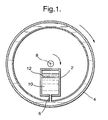
- Figure 1 depicts a centrifugal casting apparatus in accordance with a first embodiment of the invention.
- the apparatus comprises a chamber 2 and a mould 4 connected by a conduit 6.
- the chamber and mould are mounted together on a frame (not shown) which enables the two components to rotate about an axis 8.
- An alloy is added to the chamber which must be capable of withstanding the melting point of the alloy.
- the alloy may be provided as an ingot having the desired composition which is melted within the chamber. Alternatively the ingot is melted away from the chamber in a crucible or such like and added to the chamber 2 in its molten form. Additional heating elements (not shown) may be provide in or around the chamber 2 to maintain the alloy in its molten state. In the preferred embodiment, described in greater detail below, the alloy is formed during an exothermic reaction within the chamber between molten aluminium and oxides selected from titanium, vanadium and / chromium.
- the alloy may contain impurities which will affect the final characteristics of the cast component.
- the chamber 2 is rotated about the axis 8 to separate the alloy 10 from the impurity 12 centrifugally.
- a supply valve in the conduit is opened to supply the alloy to the mould 4 for the centrifugal casting process.
- the mould 4 lies further away from the axis than the chamber 2 which allows the alloy to be supplied using the generated centrifugal force.
- the alloy may be pumped from the chamber to the mould.
- the mould 4 like the chamber 2, rotates about the axis 8 and produces a sound, porous free casting with a fine grain size due to the relatively rapid solidification of the alloy and the centrifugal force exerted which breaks up dendrite formation whilst forming an accurate cast shape.
- the mould is preferably ceramic formed using a lost wax process.
- the mould is annular.
- an appropriate mould shape is required. It may be necessary to provide a counter-balance to ensure smooth rotation of the mould about the axis.
- the alloy comprises titanium, vanadium, chromium and aluminium.
- the preferred alloy has 25wt%V, 15%Cr, 2%Al with the balance being Ti plus any impurities.
- the preferred method of forming the alloy is to load the chamber 2 with titanium, vanadium and chromium oxides in powder, flake or particle form. Aluminium is added to the chamber in flake form and mixed with the other elements.
- aluminium oxides of the elements When the oxides of the elements combine with molten aluminium they react exothermically to give aluminium oxide Al 2 O 3 and liquid alloy.
- the aluminium oxide is an impurity and must be removed else the final characteristic of the alloy will be affected.
- the constituent oxides and aluminium flakes are placed in the chamber 2 as a charge.
- a mass, preferably disk shaped, and formed of the desired alloy is placed at the base of the chamber 2 to prevent the charge from entering the cast.
- the aluminium in the chamber is heated till it is melted.
- the exothermic reaction can be started by means of an electrical resistance heating wire at the point furthest from the disk.
- this technique means that the charge need not be heated en masse.
- the reaction propagates through the charge till all the powder or flakes have been converted to their base metals and alloyed. Sufficient aluminium flakes are provided so that once all the oxides have been reduced to their base metals a small proportion of the aluminium remains to be alloyed with the other components.
- Al 2 O 3 is less dense than the alloy and is squeezed to the inside of the chamber by the alloy moving outwards under the influence of the centrifugal force. The alloy may then be supplied to the mould. It typically takes less than 5 minutes for the reaction to propagate through the charge depending on the charge constituents, size of the charge and rotational speed.
- the heat of the alloy causes the disk to melt which allows the flow of molten alloy into the rotating cast component.
- the alloy continues to flow till the cast is full and it is therefore important that the volume of the cast is equal to or less than the volume of alloy formed in the chamber to stop impurities from entering the cast.
- the rotational speed and density difference between the alloy and the aluminium oxide should be sufficient to allow adequate separation before the disk melts. Routine trial and error experiments may be used to determine an acceptable rotational velocity for any given alloy and charge size to ensure adequate separation of the alloy from the impurity. By changing the properties of the disk, either physically or compositionally it is possible to change the time taken for it to melt and thereby control the supply of alloy to the cast in that way.
- the density difference between the aluminium oxide impurity at 2.5 g/cm ⁇ 3 and the alloy at around 5g/cm ⁇ 3 a revolution velocity of 200 rpm is sufficient to separate the alloy and impurity.
- the present invention offers significant advantages. Offering the ability to separate impurities from the alloy during the casting process enables high quality control and the use of alloy stock having higher levels of impurity.
- the technique enables the desired quantity of alloy to be manufactured at its point of use which overcomes the need to melt the alloy first during manufacture and again as it is used in the casting process with significant energy savings.
- the reliance on the alloy supply chain is reduced as the alloy can be made at its point of use using its constituent elements.
Landscapes
- Engineering & Computer Science (AREA)
- Mechanical Engineering (AREA)
- Manufacture And Refinement Of Metals (AREA)
Applications Claiming Priority (1)
| Application Number | Priority Date | Filing Date | Title |
|---|---|---|---|
| GBGB0717925.2A GB0717925D0 (en) | 2007-09-14 | 2007-09-14 | Centrifugal casting method and apparatus |
Publications (2)
| Publication Number | Publication Date |
|---|---|
| EP2036634A1 true EP2036634A1 (de) | 2009-03-18 |
| EP2036634B1 EP2036634B1 (de) | 2010-08-11 |
Family
ID=38658946
Family Applications (1)
| Application Number | Title | Priority Date | Filing Date |
|---|---|---|---|
| EP08252676A Not-in-force EP2036634B1 (de) | 2007-09-14 | 2008-08-12 | Schleudergiessverfahren und Vorrichtung |
Country Status (4)
| Country | Link |
|---|---|
| US (1) | US20090071622A1 (de) |
| EP (1) | EP2036634B1 (de) |
| DE (1) | DE602008002117D1 (de) |
| GB (1) | GB0717925D0 (de) |
Citations (4)
| Publication number | Priority date | Publication date | Assignee | Title |
|---|---|---|---|---|
| US3364978A (en) * | 1963-11-30 | 1968-01-23 | Sumitomo Metal Ind | Method of centrifugal casting of clean ingots |
| US4162039A (en) * | 1976-07-05 | 1979-07-24 | Aktiebolaget Skf | Feeding and mixing nozzle |
| JPH08262008A (ja) * | 1995-03-23 | 1996-10-11 | Nippon Steel Corp | 分析用サンプルの製造方法 |
| JP2000024008A (ja) * | 1998-07-15 | 2000-01-25 | Kyutai Dentceram Co Ltd | 歯科用遠心鋳造機 |
Family Cites Families (4)
| Publication number | Priority date | Publication date | Assignee | Title |
|---|---|---|---|---|
| US2899297A (en) * | 1959-08-11 | magel | ||
| US1942004A (en) * | 1930-07-29 | 1934-01-02 | Firm Th Goldschmidt A G | Process for improving aluminogenetic iron |
| US2514793A (en) * | 1949-07-19 | 1950-07-11 | Exomet | Foundry casting |
| US6935406B2 (en) * | 2003-02-06 | 2005-08-30 | Massachusetts Institute Of Technology | High pressure centrifugal casting of composites |
-
2007
- 2007-09-14 GB GBGB0717925.2A patent/GB0717925D0/en not_active Ceased
-
2008
- 2008-08-12 EP EP08252676A patent/EP2036634B1/de not_active Not-in-force
- 2008-08-12 DE DE602008002117T patent/DE602008002117D1/de active Active
- 2008-08-13 US US12/222,651 patent/US20090071622A1/en not_active Abandoned
Patent Citations (4)
| Publication number | Priority date | Publication date | Assignee | Title |
|---|---|---|---|---|
| US3364978A (en) * | 1963-11-30 | 1968-01-23 | Sumitomo Metal Ind | Method of centrifugal casting of clean ingots |
| US4162039A (en) * | 1976-07-05 | 1979-07-24 | Aktiebolaget Skf | Feeding and mixing nozzle |
| JPH08262008A (ja) * | 1995-03-23 | 1996-10-11 | Nippon Steel Corp | 分析用サンプルの製造方法 |
| JP2000024008A (ja) * | 1998-07-15 | 2000-01-25 | Kyutai Dentceram Co Ltd | 歯科用遠心鋳造機 |
Also Published As
| Publication number | Publication date |
|---|---|
| EP2036634B1 (de) | 2010-08-11 |
| GB0717925D0 (en) | 2007-10-24 |
| DE602008002117D1 (de) | 2010-09-23 |
| US20090071622A1 (en) | 2009-03-19 |
Similar Documents
| Publication | Publication Date | Title |
|---|---|---|
| US7870885B2 (en) | Method of and a device for producing a liquid-solid metal composition | |
| AU732289B2 (en) | Particulate field distributions in centrifugally cast metal matrix composites | |
| CN102869465A (zh) | 铸造长材产品 | |
| CN108728662A (zh) | 一种n06625镍基合金电渣重熔方法以及使用的渣系 | |
| CN112846126B (zh) | 多组元径向功能梯度材料设备的熔体流速调节系统及方法 | |
| CN118558975B (zh) | 一种低气孔的半固态镁合金的制备方法 | |
| JP2017512138A (ja) | 複合成分の形成 | |
| CN104561663B (zh) | 用于铸造涡轮叶轮的工艺 | |
| EP2036634B1 (de) | Schleudergiessverfahren und Vorrichtung | |
| CN101696479A (zh) | 一种铅钙合金的生产方法 | |
| JPH06142870A (ja) | 高機械的性能の部品を半流動体金属合金の射出によって製造するダイカスト方法 | |
| JP4970051B2 (ja) | 鋳造部品の製造方法 | |
| CN119304145A (zh) | 一种基于离心超重力凝固的合金材料高通量制备方法 | |
| US5253697A (en) | Manufacture of articles consisting of a composite material | |
| JP2012210655A (ja) | フィラメントの鋳造方法及び装置 | |
| CN120464898B (zh) | 一种以碳化钛作为Ti源和C源的Al-Ti-C-Ce中间合金及其制备方法和应用 | |
| CN103014390A (zh) | 一种Al3Ti颗粒增强2618铝合金复合材料的制备方法 | |
| JP2005179735A (ja) | Mg合金の製造方法およびこれに用いる製造装置 | |
| JP2003147459A (ja) | 銅合金鋳造部材および銅合金鋳造部材の製造方法 | |
| CN121057833A (zh) | 铸造过共晶铝合金盘式制动转子 | |
| CN120533064A (zh) | 一种U-Pu-Zr金属燃料凝固过程宏观均匀性控制的装置及方法 | |
| JPS59127962A (ja) | 中空複合鋳物の製造法 | |
| EP0043999B1 (de) | Verfahren zum Zentrifugalgiessen eines metallischen Gussstückes | |
| CN118204483A (zh) | 钛合金铸造方法及铸造设备 | |
| CN114687811A (zh) | 一种钛铝合金涡轮及其制备方法 |
Legal Events
| Date | Code | Title | Description |
|---|---|---|---|
| PUAI | Public reference made under article 153(3) epc to a published international application that has entered the european phase |
Free format text: ORIGINAL CODE: 0009012 |
|
| AK | Designated contracting states |
Kind code of ref document: A1 Designated state(s): AT BE BG CH CY CZ DE DK EE ES FI FR GB GR HR HU IE IS IT LI LT LU LV MC MT NL NO PL PT RO SE SI SK TR |
|
| AX | Request for extension of the european patent |
Extension state: AL BA MK RS |
|
| 17P | Request for examination filed |
Effective date: 20090507 |
|
| 17Q | First examination report despatched |
Effective date: 20090610 |
|
| AKX | Designation fees paid |
Designated state(s): DE FR GB |
|
| GRAP | Despatch of communication of intention to grant a patent |
Free format text: ORIGINAL CODE: EPIDOSNIGR1 |
|
| GRAC | Information related to communication of intention to grant a patent modified |
Free format text: ORIGINAL CODE: EPIDOSCIGR1 |
|
| GRAS | Grant fee paid |
Free format text: ORIGINAL CODE: EPIDOSNIGR3 |
|
| GRAA | (expected) grant |
Free format text: ORIGINAL CODE: 0009210 |
|
| AK | Designated contracting states |
Kind code of ref document: B1 Designated state(s): DE FR GB |
|
| REG | Reference to a national code |
Ref country code: GB Ref legal event code: FG4D |
|
| REF | Corresponds to: |
Ref document number: 602008002117 Country of ref document: DE Date of ref document: 20100923 Kind code of ref document: P |
|
| PLBE | No opposition filed within time limit |
Free format text: ORIGINAL CODE: 0009261 |
|
| STAA | Information on the status of an ep patent application or granted ep patent |
Free format text: STATUS: NO OPPOSITION FILED WITHIN TIME LIMIT |
|
| 26N | No opposition filed |
Effective date: 20110512 |
|
| REG | Reference to a national code |
Ref country code: DE Ref legal event code: R097 Ref document number: 602008002117 Country of ref document: DE Effective date: 20110512 |
|
| PGFP | Annual fee paid to national office [announced via postgrant information from national office to epo] |
Ref country code: DE Payment date: 20130828 Year of fee payment: 6 |
|
| PGFP | Annual fee paid to national office [announced via postgrant information from national office to epo] |
Ref country code: GB Payment date: 20130827 Year of fee payment: 6 Ref country code: FR Payment date: 20130819 Year of fee payment: 6 |
|
| REG | Reference to a national code |
Ref country code: DE Ref legal event code: R119 Ref document number: 602008002117 Country of ref document: DE |
|
| GBPC | Gb: european patent ceased through non-payment of renewal fee |
Effective date: 20140812 |
|
| REG | Reference to a national code |
Ref country code: DE Ref legal event code: R119 Ref document number: 602008002117 Country of ref document: DE Effective date: 20150303 |
|
| REG | Reference to a national code |
Ref country code: FR Ref legal event code: ST Effective date: 20150430 |
|
| PG25 | Lapsed in a contracting state [announced via postgrant information from national office to epo] |
Ref country code: GB Free format text: LAPSE BECAUSE OF NON-PAYMENT OF DUE FEES Effective date: 20140812 Ref country code: DE Free format text: LAPSE BECAUSE OF NON-PAYMENT OF DUE FEES Effective date: 20150303 |
|
| PG25 | Lapsed in a contracting state [announced via postgrant information from national office to epo] |
Ref country code: FR Free format text: LAPSE BECAUSE OF NON-PAYMENT OF DUE FEES Effective date: 20140901 |