EP2036636B1 - Tête raccordement d'outil pour un tour - Google Patents
Tête raccordement d'outil pour un tour Download PDFInfo
- Publication number
- EP2036636B1 EP2036636B1 EP20080016039 EP08016039A EP2036636B1 EP 2036636 B1 EP2036636 B1 EP 2036636B1 EP 20080016039 EP20080016039 EP 20080016039 EP 08016039 A EP08016039 A EP 08016039A EP 2036636 B1 EP2036636 B1 EP 2036636B1
- Authority
- EP
- European Patent Office
- Prior art keywords
- tool
- holding head
- axis
- head according
- quick
- Prior art date
- Legal status (The legal status is an assumption and is not a legal conclusion. Google has not performed a legal analysis and makes no representation as to the accuracy of the status listed.)
- Not-in-force
Links
- 238000005553 drilling Methods 0.000 claims description 21
- 238000003754 machining Methods 0.000 description 5
- 238000003801 milling Methods 0.000 description 3
- 230000008878 coupling Effects 0.000 description 1
- 238000010168 coupling process Methods 0.000 description 1
- 238000005859 coupling reaction Methods 0.000 description 1
Images


Classifications
-
- B—PERFORMING OPERATIONS; TRANSPORTING
- B23—MACHINE TOOLS; METAL-WORKING NOT OTHERWISE PROVIDED FOR
- B23B—TURNING; BORING
- B23B29/00—Holders for non-rotary cutting tools; Boring bars or boring heads; Accessories for tool holders
- B23B29/24—Tool holders for a plurality of cutting tools, e.g. turrets
- B23B29/32—Turrets adjustable by power drive, i.e. turret heads
- B23B29/323—Turrets with power operated angular positioning devices
-
- B—PERFORMING OPERATIONS; TRANSPORTING
- B23—MACHINE TOOLS; METAL-WORKING NOT OTHERWISE PROVIDED FOR
- B23B—TURNING; BORING
- B23B3/00—General-purpose turning-machines or devices, e.g. centre lathes with feed rod and lead screw; Sets of turning-machines
- B23B3/16—Turret lathes for turning individually-chucked workpieces
- B23B3/167—Turret lathes for turning individually-chucked workpieces lathe with two or more toolslides carrying turrets
- B23B3/168—Arrangements for performing other machining operations, e.g. milling, drilling
-
- B—PERFORMING OPERATIONS; TRANSPORTING
- B23—MACHINE TOOLS; METAL-WORKING NOT OTHERWISE PROVIDED FOR
- B23Q—DETAILS, COMPONENTS, OR ACCESSORIES FOR MACHINE TOOLS, e.g. ARRANGEMENTS FOR COPYING OR CONTROLLING; MACHINE TOOLS IN GENERAL CHARACTERISED BY THE CONSTRUCTION OF PARTICULAR DETAILS OR COMPONENTS; COMBINATIONS OR ASSOCIATIONS OF METAL-WORKING MACHINES, NOT DIRECTED TO A PARTICULAR RESULT
- B23Q1/00—Members which are comprised in the general build-up of a form of machine, particularly relatively large fixed members
- B23Q1/70—Stationary or movable members for carrying working-spindles for attachment of tools or work
-
- B—PERFORMING OPERATIONS; TRANSPORTING
- B23—MACHINE TOOLS; METAL-WORKING NOT OTHERWISE PROVIDED FOR
- B23Q—DETAILS, COMPONENTS, OR ACCESSORIES FOR MACHINE TOOLS, e.g. ARRANGEMENTS FOR COPYING OR CONTROLLING; MACHINE TOOLS IN GENERAL CHARACTERISED BY THE CONSTRUCTION OF PARTICULAR DETAILS OR COMPONENTS; COMBINATIONS OR ASSOCIATIONS OF METAL-WORKING MACHINES, NOT DIRECTED TO A PARTICULAR RESULT
- B23Q5/00—Driving or feeding mechanisms; Control arrangements therefor
- B23Q5/02—Driving main working members
- B23Q5/04—Driving main working members rotary shafts, e.g. working-spindles
- B23Q5/043—Accessories for spindle drives
- B23Q5/045—Angle drives
-
- B—PERFORMING OPERATIONS; TRANSPORTING
- B23—MACHINE TOOLS; METAL-WORKING NOT OTHERWISE PROVIDED FOR
- B23Q—DETAILS, COMPONENTS, OR ACCESSORIES FOR MACHINE TOOLS, e.g. ARRANGEMENTS FOR COPYING OR CONTROLLING; MACHINE TOOLS IN GENERAL CHARACTERISED BY THE CONSTRUCTION OF PARTICULAR DETAILS OR COMPONENTS; COMBINATIONS OR ASSOCIATIONS OF METAL-WORKING MACHINES, NOT DIRECTED TO A PARTICULAR RESULT
- B23Q5/00—Driving or feeding mechanisms; Control arrangements therefor
- B23Q5/02—Driving main working members
- B23Q5/04—Driving main working members rotary shafts, e.g. working-spindles
- B23Q5/20—Adjusting or stopping working-spindles in a predetermined position
Definitions
- the above invention relates to a tool receiving head for a lathe, in particular for a multi-spindle lathe.
- the known tool holder heads are slidably mounted with the aid of dovetail guides.
- tool receiving heads which receive rotating tools, e.g. Drilling or milling tools.
- Out DE-A-3702424 is a tool turret for a machine tool, in particular a lathe, known.
- a drive motor is provided with a first axis of rotation which acts on a second shaft, whose axis is arranged in a second plane and acts via a gear on a third drive shaft for driving a tool which is rotatable about an angular drive about a fourth axis.
- the object of the invention is achieved with a tool receiving head for a lathe according to claim 1.
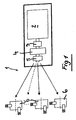
- the tool holder head 1 on a controllable motor 2 has a connector 3, a quick connector 4 and a hydraulic brake 5.
- the tool receiving head 1 is equipped with a variety of tools.
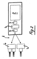
- FIG. 2 Another embodiment of the tool receiving head is in FIG. 2 also shown here, a motor 2, a connector 3, a quick connector 4 and a hydraulic brake 5 are provided which drive in this case tool groups.
- the hydraulic brake 5 When the fixed tools are in the working position, the hydraulic brake 5 is actuated in order to lock the tools in a specific working position. If, however, a number of rotating tools is provided, the brake 5 is released.
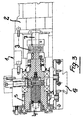
- FIG. 3 can be taken in detail in detail the drive motor 2, the drive shaft 7, a coupling piece 3 and the quick connector 4, a tool (not shown in FIG FIG. 3 ) is set in rotary motion.
- the quick connector is known in the art.
- the tool holder head 1 can be locked in any desired position.
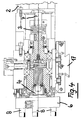
- FIG. 4 can be taken from the drive motor 2 with the associated drive shaft 7; the drive motor 2 drives via a connector 3 to the quick connector 4, which according to FIG. 4 a receptacle 6, which is equipped with numerous stationary tools 8 for performing shooting.
- the tool receiving head 1 is allowed to receive a disk-like tool holder, on which numerous fixed workpieces are arranged for performing radial and frontal machining operations.
- the motor 2 is controlled such that a precision machining of the workpiece is possible, further there is a tool change, whereby the desired machining tool is moved to the processing position.
- the presence of a hydraulic brake 5 allows locking of the turret in a secure and rigid position.
- the motor is operated to give the tool the necessary torque.
- the hydraulic brake 5 is unlocked.
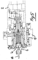
- FIG. 5 can always be the engine 2 with the associated drive shaft 7, the connector 3 and the quick connector 4 are removed.
- the receptacle (6) has a bearing, which has a drilling tool 18 which lies in axis to the motor 2.
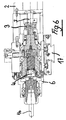
- FIG. 6 the receptacle 6 is shown and equipped with a tool 16 with a larger diameter to perform drilling or milling operations with larger chip removal.
- the tool holder head 1 has a slide 17 in dovetail guide on its underside, thereby allowing a displaceable mounting in the body of the machine tool.
- FIG. 7 shows in section part of the tool holder head, which is suitable for the implementation of a 90 ° deflected bore.
- the tool marked 18 is used to perform in the workpiece P holes in the axis.
- a plate 30 is provided, which serves to tension the drilling tool 18.
- the plate 30 is pivotable and lockable by providing oblong holes 31 arranged along a circular arc line.
- a suitable key on a gear 32 Before use of the drilling tool 18 is acted upon with the aid of a suitable key on a gear 32, thereby making it possible to the teeth 33 of the plate 30th act and thus make a positional arrangement of the drilling tool 18 relative to the workpiece.
- FIG. 9 shows that thanks to an operation on the devices 32, 33 of the plate 30 a pivoting movement about the axis Z has been carried out, whereby the drilling tool 18 was no longer pivoted in axis with the workpiece, but slightly to the left in the drawing, whereby the position of to be performed hole outside the axis of the tool piece P comes to rest.
- the pivoting movement of the plate 31 can take place both to the left and to the right about the axis Z.
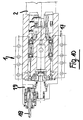
- FIG. 10 shows in section the tool holder with the drilling tool 18, which is received by the device 19 and is offset radially relative to the longitudinal axis of the device.
Landscapes
- Engineering & Computer Science (AREA)
- Mechanical Engineering (AREA)
- Gripping On Spindles (AREA)
- Cutting Tools, Boring Holders, And Turrets (AREA)
- Drilling And Boring (AREA)
Claims (7)
- Tête de réception d'outil (1) pour un tour, montée de manière déplaçable en utilisant un guide en queue d'aronde (17),
caractérisée en ce que
la tête de réception (1) présente un moteur commandable (2) dont l'arbre d'entraînement (7) agit par le biais d'une pièce de liaison (3) sur un raccord rapide (4) auquel est associé un frein hydraulique (5), et le raccord rapide (4) présente un logement (6) pour un outil rotatif ou un support sur palier pour recevoir un outil disposé fixement (8),
le moteur (2), l'arbre d'entraînement (7), la pièce de liaison (3), le raccord rapide (4) ainsi que le frein hydraulique étant disposés en rang le long d'un axe longitudinal commun. - Tête de réception d'outil selon la revendication 1, caractérisée en ce que le raccord rapide (4) présente un logement (6) qui peut être garni d'un outil de perçage (18, 16).
- Tête de réception d'outil selon la revendication 1, caractérisée en ce que le logement (6) est muni d'un outil de perçage (18) qui est disposé de manière décalée de 90° par rapport à l'axe (X) de la tête de réception (1).
- Tête de réception d'outil selon la revendication 1, caractérisée en ce que le dispositif (19) pour recevoir l'outil de perçage (18) est équipé pour effectuer des perçages décalés radialement par rapport à la pièce ainsi que pour réaliser des perçages en coïncidence avec l'axe de la pièce ainsi que pour réaliser des perçages à l'extérieur de l'axe ainsi que pour réaliser des perçages radialement par rapport à la pièce (P).
- Tête de réception d'outil selon la revendication 1, caractérisée en ce que l'outil de perçage (18) est reçu par le biais de moyens ajustables dans sa position par une plaque pouvant pivoter autour de l'axe (Z).
- Tête de réception d'outil selon la revendication 1, caractérisée en ce que la plaque (30) est reçue par un composant qui présente, dans la direction périphérique, une denture qui est en liaison avec une roue d'entraînement, qui est munie d'un évidement pour l'insertion d'une clé d'ajustement.
- Tête de réception d'outil selon la revendication 6, caractérisée en ce que la plaque (30) présente des trous oblongs (31) afin de serrer l'outil (18) dans la position sélectionnée, en utilisant des vis.
Applications Claiming Priority (1)
| Application Number | Priority Date | Filing Date | Title |
|---|---|---|---|
| ITMI20071770 ITMI20071770A1 (it) | 2007-09-14 | 2007-09-14 | Torretta portautensili per una macchina di tornitura |
Publications (2)
| Publication Number | Publication Date |
|---|---|
| EP2036636A1 EP2036636A1 (fr) | 2009-03-18 |
| EP2036636B1 true EP2036636B1 (fr) | 2012-06-20 |
Family
ID=40030281
Family Applications (1)
| Application Number | Title | Priority Date | Filing Date |
|---|---|---|---|
| EP20080016039 Not-in-force EP2036636B1 (fr) | 2007-09-14 | 2008-09-11 | Tête raccordement d'outil pour un tour |
Country Status (2)
| Country | Link |
|---|---|
| EP (1) | EP2036636B1 (fr) |
| IT (1) | ITMI20071770A1 (fr) |
Family Cites Families (4)
| Publication number | Priority date | Publication date | Assignee | Title |
|---|---|---|---|---|
| DE3702424A1 (de) | 1987-01-28 | 1988-08-11 | Boley Gmbh & Co Werkzeugmaschi | Werkzeugrevolver fuer werkzeugmaschinen, insbesondere drehmaschinen |
| DE8712581U1 (de) * | 1987-09-17 | 1989-01-12 | Pittler GmbH, 6070 Langen | Verriegelbare Werkzeugaufnahme |
| DE3930154A1 (de) * | 1989-09-09 | 1991-03-21 | Gildemeister Max Mueller Gmbh | Werkzeugspannkopf |
| JP3254648B2 (ja) * | 1992-06-18 | 2002-02-12 | ブラザー工業株式会社 | 工作機械の自動工具交換装置 |
-
2007
- 2007-09-14 IT ITMI20071770 patent/ITMI20071770A1/it unknown
-
2008
- 2008-09-11 EP EP20080016039 patent/EP2036636B1/fr not_active Not-in-force
Also Published As
| Publication number | Publication date |
|---|---|
| EP2036636A1 (fr) | 2009-03-18 |
| ITMI20071770A1 (it) | 2009-03-15 |
Similar Documents
| Publication | Publication Date | Title |
|---|---|---|
| EP1224048B1 (fr) | Porte-outil | |
| EP0054838B1 (fr) | Tête à surfacer et à aléser ainsi que machine-outil pour serrer cet outil | |
| DE102018126260B4 (de) | Maschine und Verfahren zum Schleifen dünnwandiger Werkstücke | |
| DE3010934C2 (fr) | ||
| DE3913139C2 (fr) | ||
| DE102011082501A1 (de) | Werkstück-Positioniereinrichtung für eine Werkzeugmaschine und Werkzeugmaschine mit einer derartigen Werkstück-Positioniereinrichtung | |
| DE9306460U1 (de) | Drehautomat | |
| EP1884303B1 (fr) | Procédé destiné à centrer des pièces à usiner tout comme dispositif destiné à la réalisation d'un tel procédé | |
| DE69012585T2 (de) | Drehautomat mit unbeweglichem spindelstock und aufbearbeitungsspindel. | |
| DE3725014C2 (fr) | ||
| EP3081324A1 (fr) | Tour à poupée mobile comprenant deux axes d'usinage à commande numérique et procédé destiné à usiner des pièces sur un tour a poupée mobile comprenant deux axes d'usinage à commande numérique | |
| DE3106800C2 (de) | Spindelstock eines Bearbeitungszentrums | |
| DE2130649C3 (fr) | ||
| EP1797994A1 (fr) | Dispositif ébarbeur | |
| EP0755315B1 (fr) | Tour multibroche | |
| DE3528437C2 (fr) | ||
| EP2036636B1 (fr) | Tête raccordement d'outil pour un tour | |
| AT505069B1 (de) | Werkzeugrevolver | |
| DE102018007186B4 (de) | Spannbackensystem | |
| DE19710447C2 (de) | Vorrichtung zur Werkstückzuführung in einen Einspannbereich einer Werkzeugmaschine | |
| EP4263133B1 (fr) | Flasque récepteur destiné à un corps d'outil | |
| DE4419610C2 (de) | CNC-Drehmaschine für schwere Zerspanung | |
| WO2012130444A1 (fr) | Dispositif d'alignement de guide pour magasin de chargement de barres et procédé correspondant | |
| DE102006048495A1 (de) | Bearbeitungssystem zur spanenden Fertigbearbeitung von Pleuelaugen | |
| DE3518287C2 (fr) |
Legal Events
| Date | Code | Title | Description |
|---|---|---|---|
| PUAI | Public reference made under article 153(3) epc to a published international application that has entered the european phase |
Free format text: ORIGINAL CODE: 0009012 |
|
| AK | Designated contracting states |
Kind code of ref document: A1 Designated state(s): AT BE BG CH CY CZ DE DK EE ES FI FR GB GR HR HU IE IS IT LI LT LU LV MC MT NL NO PL PT RO SE SI SK TR |
|
| AX | Request for extension of the european patent |
Extension state: AL BA MK RS |
|
| 17P | Request for examination filed |
Effective date: 20090911 |
|
| 17Q | First examination report despatched |
Effective date: 20091012 |
|
| AKX | Designation fees paid |
Designated state(s): AT BE BG CH CY CZ DE DK EE ES FI FR GB GR HR HU IE IS IT LI LT LU LV MC MT NL NO PL PT RO SE SI SK TR |
|
| GRAP | Despatch of communication of intention to grant a patent |
Free format text: ORIGINAL CODE: EPIDOSNIGR1 |
|
| GRAS | Grant fee paid |
Free format text: ORIGINAL CODE: EPIDOSNIGR3 |
|
| GRAA | (expected) grant |
Free format text: ORIGINAL CODE: 0009210 |
|
| AK | Designated contracting states |
Kind code of ref document: B1 Designated state(s): AT BE BG CH CY CZ DE DK EE ES FI FR GB GR HR HU IE IS IT LI LT LU LV MC MT NL NO PL PT RO SE SI SK TR |
|
| REG | Reference to a national code |
Ref country code: GB Ref legal event code: FG4D Free format text: NOT ENGLISH |
|
| REG | Reference to a national code |
Ref country code: CH Ref legal event code: EP |
|
| REG | Reference to a national code |
Ref country code: AT Ref legal event code: REF Ref document number: 562732 Country of ref document: AT Kind code of ref document: T Effective date: 20120715 |
|
| REG | Reference to a national code |
Ref country code: IE Ref legal event code: FG4D Free format text: LANGUAGE OF EP DOCUMENT: GERMAN |
|
| REG | Reference to a national code |
Ref country code: DE Ref legal event code: R096 Ref document number: 502008007450 Country of ref document: DE Effective date: 20120816 |
|
| REG | Reference to a national code |
Ref country code: CH Ref legal event code: NV Representative=s name: FREI PATENTANWALTSBUERO |
|
| PG25 | Lapsed in a contracting state [announced via postgrant information from national office to epo] |
Ref country code: LT Free format text: LAPSE BECAUSE OF FAILURE TO SUBMIT A TRANSLATION OF THE DESCRIPTION OR TO PAY THE FEE WITHIN THE PRESCRIBED TIME-LIMIT Effective date: 20120620 Ref country code: NO Free format text: LAPSE BECAUSE OF FAILURE TO SUBMIT A TRANSLATION OF THE DESCRIPTION OR TO PAY THE FEE WITHIN THE PRESCRIBED TIME-LIMIT Effective date: 20120920 Ref country code: FI Free format text: LAPSE BECAUSE OF FAILURE TO SUBMIT A TRANSLATION OF THE DESCRIPTION OR TO PAY THE FEE WITHIN THE PRESCRIBED TIME-LIMIT Effective date: 20120620 Ref country code: SE Free format text: LAPSE BECAUSE OF FAILURE TO SUBMIT A TRANSLATION OF THE DESCRIPTION OR TO PAY THE FEE WITHIN THE PRESCRIBED TIME-LIMIT Effective date: 20120620 |
|
| REG | Reference to a national code |
Ref country code: NL Ref legal event code: VDEP Effective date: 20120620 |
|
| REG | Reference to a national code |
Ref country code: LT Ref legal event code: MG4D Effective date: 20120620 |
|
| PG25 | Lapsed in a contracting state [announced via postgrant information from national office to epo] |
Ref country code: GR Free format text: LAPSE BECAUSE OF FAILURE TO SUBMIT A TRANSLATION OF THE DESCRIPTION OR TO PAY THE FEE WITHIN THE PRESCRIBED TIME-LIMIT Effective date: 20120921 Ref country code: SI Free format text: LAPSE BECAUSE OF FAILURE TO SUBMIT A TRANSLATION OF THE DESCRIPTION OR TO PAY THE FEE WITHIN THE PRESCRIBED TIME-LIMIT Effective date: 20120620 Ref country code: LV Free format text: LAPSE BECAUSE OF FAILURE TO SUBMIT A TRANSLATION OF THE DESCRIPTION OR TO PAY THE FEE WITHIN THE PRESCRIBED TIME-LIMIT Effective date: 20120620 Ref country code: HR Free format text: LAPSE BECAUSE OF FAILURE TO SUBMIT A TRANSLATION OF THE DESCRIPTION OR TO PAY THE FEE WITHIN THE PRESCRIBED TIME-LIMIT Effective date: 20120620 |
|
| PG25 | Lapsed in a contracting state [announced via postgrant information from national office to epo] |
Ref country code: SK Free format text: LAPSE BECAUSE OF FAILURE TO SUBMIT A TRANSLATION OF THE DESCRIPTION OR TO PAY THE FEE WITHIN THE PRESCRIBED TIME-LIMIT Effective date: 20120620 Ref country code: EE Free format text: LAPSE BECAUSE OF FAILURE TO SUBMIT A TRANSLATION OF THE DESCRIPTION OR TO PAY THE FEE WITHIN THE PRESCRIBED TIME-LIMIT Effective date: 20120620 Ref country code: IS Free format text: LAPSE BECAUSE OF FAILURE TO SUBMIT A TRANSLATION OF THE DESCRIPTION OR TO PAY THE FEE WITHIN THE PRESCRIBED TIME-LIMIT Effective date: 20121020 Ref country code: RO Free format text: LAPSE BECAUSE OF FAILURE TO SUBMIT A TRANSLATION OF THE DESCRIPTION OR TO PAY THE FEE WITHIN THE PRESCRIBED TIME-LIMIT Effective date: 20120620 Ref country code: CY Free format text: LAPSE BECAUSE OF FAILURE TO SUBMIT A TRANSLATION OF THE DESCRIPTION OR TO PAY THE FEE WITHIN THE PRESCRIBED TIME-LIMIT Effective date: 20120620 Ref country code: CZ Free format text: LAPSE BECAUSE OF FAILURE TO SUBMIT A TRANSLATION OF THE DESCRIPTION OR TO PAY THE FEE WITHIN THE PRESCRIBED TIME-LIMIT Effective date: 20120620 |
|
| PG25 | Lapsed in a contracting state [announced via postgrant information from national office to epo] |
Ref country code: PT Free format text: LAPSE BECAUSE OF FAILURE TO SUBMIT A TRANSLATION OF THE DESCRIPTION OR TO PAY THE FEE WITHIN THE PRESCRIBED TIME-LIMIT Effective date: 20121022 Ref country code: PL Free format text: LAPSE BECAUSE OF FAILURE TO SUBMIT A TRANSLATION OF THE DESCRIPTION OR TO PAY THE FEE WITHIN THE PRESCRIBED TIME-LIMIT Effective date: 20120620 |
|
| PG25 | Lapsed in a contracting state [announced via postgrant information from national office to epo] |
Ref country code: NL Free format text: LAPSE BECAUSE OF FAILURE TO SUBMIT A TRANSLATION OF THE DESCRIPTION OR TO PAY THE FEE WITHIN THE PRESCRIBED TIME-LIMIT Effective date: 20120620 |
|
| BERE | Be: lapsed |
Owner name: GILDEMEISTER ITALIANA S.P.A. Effective date: 20120930 |
|
| PLBE | No opposition filed within time limit |
Free format text: ORIGINAL CODE: 0009261 |
|
| STAA | Information on the status of an ep patent application or granted ep patent |
Free format text: STATUS: NO OPPOSITION FILED WITHIN TIME LIMIT |
|
| PG25 | Lapsed in a contracting state [announced via postgrant information from national office to epo] |
Ref country code: MC Free format text: LAPSE BECAUSE OF NON-PAYMENT OF DUE FEES Effective date: 20120930 Ref country code: DK Free format text: LAPSE BECAUSE OF FAILURE TO SUBMIT A TRANSLATION OF THE DESCRIPTION OR TO PAY THE FEE WITHIN THE PRESCRIBED TIME-LIMIT Effective date: 20120620 |
|
| 26N | No opposition filed |
Effective date: 20130321 |
|
| GBPC | Gb: european patent ceased through non-payment of renewal fee |
Effective date: 20120920 |
|
| REG | Reference to a national code |
Ref country code: IE Ref legal event code: MM4A |
|
| REG | Reference to a national code |
Ref country code: DE Ref legal event code: R097 Ref document number: 502008007450 Country of ref document: DE Effective date: 20130321 |
|
| PG25 | Lapsed in a contracting state [announced via postgrant information from national office to epo] |
Ref country code: BE Free format text: LAPSE BECAUSE OF NON-PAYMENT OF DUE FEES Effective date: 20120930 Ref country code: GB Free format text: LAPSE BECAUSE OF NON-PAYMENT OF DUE FEES Effective date: 20120920 Ref country code: IE Free format text: LAPSE BECAUSE OF NON-PAYMENT OF DUE FEES Effective date: 20120911 Ref country code: BG Free format text: LAPSE BECAUSE OF FAILURE TO SUBMIT A TRANSLATION OF THE DESCRIPTION OR TO PAY THE FEE WITHIN THE PRESCRIBED TIME-LIMIT Effective date: 20120920 |
|
| PG25 | Lapsed in a contracting state [announced via postgrant information from national office to epo] |
Ref country code: ES Free format text: LAPSE BECAUSE OF FAILURE TO SUBMIT A TRANSLATION OF THE DESCRIPTION OR TO PAY THE FEE WITHIN THE PRESCRIBED TIME-LIMIT Effective date: 20121001 |
|
| PG25 | Lapsed in a contracting state [announced via postgrant information from national office to epo] |
Ref country code: MT Free format text: LAPSE BECAUSE OF FAILURE TO SUBMIT A TRANSLATION OF THE DESCRIPTION OR TO PAY THE FEE WITHIN THE PRESCRIBED TIME-LIMIT Effective date: 20120620 |
|
| PG25 | Lapsed in a contracting state [announced via postgrant information from national office to epo] |
Ref country code: TR Free format text: LAPSE BECAUSE OF FAILURE TO SUBMIT A TRANSLATION OF THE DESCRIPTION OR TO PAY THE FEE WITHIN THE PRESCRIBED TIME-LIMIT Effective date: 20120620 |
|
| PG25 | Lapsed in a contracting state [announced via postgrant information from national office to epo] |
Ref country code: LU Free format text: LAPSE BECAUSE OF NON-PAYMENT OF DUE FEES Effective date: 20120911 |
|
| PG25 | Lapsed in a contracting state [announced via postgrant information from national office to epo] |
Ref country code: HU Free format text: LAPSE BECAUSE OF FAILURE TO SUBMIT A TRANSLATION OF THE DESCRIPTION OR TO PAY THE FEE WITHIN THE PRESCRIBED TIME-LIMIT Effective date: 20080911 |
|
| REG | Reference to a national code |
Ref country code: AT Ref legal event code: MM01 Ref document number: 562732 Country of ref document: AT Kind code of ref document: T Effective date: 20130911 |
|
| PG25 | Lapsed in a contracting state [announced via postgrant information from national office to epo] |
Ref country code: AT Free format text: LAPSE BECAUSE OF NON-PAYMENT OF DUE FEES Effective date: 20130911 |
|
| REG | Reference to a national code |
Ref country code: FR Ref legal event code: PLFP Year of fee payment: 9 |
|
| REG | Reference to a national code |
Ref country code: FR Ref legal event code: PLFP Year of fee payment: 10 |
|
| REG | Reference to a national code |
Ref country code: FR Ref legal event code: PLFP Year of fee payment: 11 |
|
| REG | Reference to a national code |
Ref country code: CH Ref legal event code: PFA Owner name: GILDEMEISTER ITALIANA S.P.A., IT Free format text: FORMER OWNER: GILDEMEISTER ITALIANA S.P.A., IT |
|
| PGFP | Annual fee paid to national office [announced via postgrant information from national office to epo] |
Ref country code: FR Payment date: 20190925 Year of fee payment: 12 |
|
| PGFP | Annual fee paid to national office [announced via postgrant information from national office to epo] |
Ref country code: CH Payment date: 20190925 Year of fee payment: 12 Ref country code: DE Payment date: 20191002 Year of fee payment: 12 |
|
| PGFP | Annual fee paid to national office [announced via postgrant information from national office to epo] |
Ref country code: IT Payment date: 20190930 Year of fee payment: 12 |
|
| REG | Reference to a national code |
Ref country code: DE Ref legal event code: R119 Ref document number: 502008007450 Country of ref document: DE |
|
| REG | Reference to a national code |
Ref country code: CH Ref legal event code: PL |
|
| PG25 | Lapsed in a contracting state [announced via postgrant information from national office to epo] |
Ref country code: FR Free format text: LAPSE BECAUSE OF NON-PAYMENT OF DUE FEES Effective date: 20200930 Ref country code: DE Free format text: LAPSE BECAUSE OF NON-PAYMENT OF DUE FEES Effective date: 20210401 |
|
| PG25 | Lapsed in a contracting state [announced via postgrant information from national office to epo] |
Ref country code: CH Free format text: LAPSE BECAUSE OF NON-PAYMENT OF DUE FEES Effective date: 20200930 Ref country code: LI Free format text: LAPSE BECAUSE OF NON-PAYMENT OF DUE FEES Effective date: 20200930 |
|
| PG25 | Lapsed in a contracting state [announced via postgrant information from national office to epo] |
Ref country code: IT Free format text: LAPSE BECAUSE OF NON-PAYMENT OF DUE FEES Effective date: 20200911 |