EP2036645A2 - Agencement de chariot pour une machine-outil - Google Patents
Agencement de chariot pour une machine-outil Download PDFInfo
- Publication number
- EP2036645A2 EP2036645A2 EP08016008A EP08016008A EP2036645A2 EP 2036645 A2 EP2036645 A2 EP 2036645A2 EP 08016008 A EP08016008 A EP 08016008A EP 08016008 A EP08016008 A EP 08016008A EP 2036645 A2 EP2036645 A2 EP 2036645A2
- Authority
- EP
- European Patent Office
- Prior art keywords
- carriage
- movement
- axis
- adjusting movement
- workpiece
- Prior art date
- Legal status (The legal status is an assumption and is not a legal conclusion. Google has not performed a legal analysis and makes no representation as to the accuracy of the status listed.)
- Withdrawn
Links
Images
Classifications
-
- B—PERFORMING OPERATIONS; TRANSPORTING
- B23—MACHINE TOOLS; METAL-WORKING NOT OTHERWISE PROVIDED FOR
- B23Q—DETAILS, COMPONENTS, OR ACCESSORIES FOR MACHINE TOOLS, e.g. ARRANGEMENTS FOR COPYING OR CONTROLLING; MACHINE TOOLS IN GENERAL CHARACTERISED BY THE CONSTRUCTION OF PARTICULAR DETAILS OR COMPONENTS; COMBINATIONS OR ASSOCIATIONS OF METAL-WORKING MACHINES, NOT DIRECTED TO A PARTICULAR RESULT
- B23Q17/00—Arrangements for observing, indicating or measuring on machine tools
- B23Q17/22—Arrangements for observing, indicating or measuring on machine tools for indicating or measuring existing or desired position of tool or work
-
- B—PERFORMING OPERATIONS; TRANSPORTING
- B23—MACHINE TOOLS; METAL-WORKING NOT OTHERWISE PROVIDED FOR
- B23Q—DETAILS, COMPONENTS, OR ACCESSORIES FOR MACHINE TOOLS, e.g. ARRANGEMENTS FOR COPYING OR CONTROLLING; MACHINE TOOLS IN GENERAL CHARACTERISED BY THE CONSTRUCTION OF PARTICULAR DETAILS OR COMPONENTS; COMBINATIONS OR ASSOCIATIONS OF METAL-WORKING MACHINES, NOT DIRECTED TO A PARTICULAR RESULT
- B23Q5/00—Driving or feeding mechanisms; Control arrangements therefor
- B23Q5/22—Feeding members carrying tools or work
- B23Q5/34—Feeding other members supporting tools or work, e.g. saddles, tool-slides, through mechanical transmission
- B23Q5/341—Feeding other members supporting tools or work, e.g. saddles, tool-slides, through mechanical transmission cam-operated
Definitions
- the invention relates to a carriage arrangement for a machine tool having a first carriage which can be adjusted along a first axis of movement, by the adjusting movement of which a workpiece supported on the first carriage is adjustable between a first position and a second position and with a second carriage which is adjustable along a second axis of movement , By the adjustment of which a sensor supported on the second carriage can be adjusted between a measuring position approximated to the first position of the workpiece and a rest position withdrawn from the measuring position.
- Such carriage arrangements are used in particular in machine tools, which are used for fine machining of gear blanks.
- an indexing ie a detection of their rotational position by the probe required, so that suitable for fine machining relative position between the workpiece and a machining tool, such as a honing wheel, can be adjusted.
- usually forming the workpiece gear blank is clamped on a rotatably driven work spindle, which is supported on the first carriage.
- the first carriage supporting the workpiece is brought into its first position and the sensor forming the indexing sensor is brought very close to the workpiece by adjusting the second carriage supporting the sensor to its measuring position.
- the second carriage must be retracted to its rest position withdrawn from the measuring position so that the workpiece on the first carriage can be transferred to its second position for fine machining without collision between the sensor and the workpiece during this adjustment movement which comes the workpiece clamping jig or the workpiece carrying the first carriage.
- these adjustment movements are realized by an electric, pneumatic or hydraulic drive.
- the instantaneous position of the second carriage supporting the sensor is interrogated by position sensors.
- the adjustment movement of the workpiece carrying the first carriage from its first position in which the indexing has been performed, and its second position, from which the workpiece is brought into engagement with the machining tool, is only started when the second carriage monitoring Position sensors release an enable signal.
- the retraction of the probe from its measuring position and the ancestor of the workpiece in its second position take place in succession.
- the invention has the object of providing a slide assembly of the type mentioned in such a way that these non-productive times are shortened.
- this object is achieved in that a driven by the adjustment of the first carriage actuator is provided by the adjusting movement of the second carriage from the first position to the second position due to the adjusting movement of the second carriage from the measuring position to the rest position and due Adjusting movement of the first carriage from the second position to the first position, the adjusting movement of the second carriage from the rest position to the measuring position can be driven.
- the process of adjustment of the probe between its measuring position and its rest position and the process of adjustment of the workpiece between its first and its second position are parallelized.
- the inventively provided actuator causes a mechanically positively guided coupling of the adjustment movements of the two carriages. Characterized the retraction movement of the sensor supporting the second carriage is forcibly controlled by the advancing movement of the workpiece carrying the first carriage such that with the advancing movement of the first carriage, the second carriage is forcibly withdrawn from the collision area.
- the invention is particularly applicable to the case that the first movement axis and the second movement axis are linear and mutually orthogonal.
- the linear adjustment movement of the first carriage is converted by the actuating device into an orthogonal, lateral adjustment movement of the second carriage.
- the workpiece is mounted on a supported on the first slide, rotatably driven work spindle whose spindle axis extends parallel to the first axis of movement.
- the sensor carrying the second carriage then deviates laterally at a feed movement of the workpiece orthogonal to the spindle axis.
- the actuating device has a cam track fixed to the first carriage and a lever arrangement having a first lever arm, a second lever arm and a pivot axis stationary with respect to the two carriages, the first lever arm as a result of the adjusting movement of the first carriage from the curved path is pivoted and their second lever arm thereby drives the adjustment movement of the second carriage.
- the first lever arm experiences a corresponding pivoting, which is converted by the second lever arm into a corresponding drive movement for the second slide.
- the curved path may have two track sections which are parallel to the first movement axis but at different distances therefrom and which are interconnected by a ramp-shaped track section.
- the two track sections parallel to the first movement axis determine the two end positions of the pivoting of the first lever arm, while the action of the ramped track section causes the pivoting between these two end positions.
- the mediation of the action of the cam track on the first lever arm is advantageously carried out in that the first lever arm has a rotatably mounted thereon and rolling on the curved path roller.
- the cam track may for example be designed such that it forcibly leads the roller between two mutually uniform control cams.
- a particularly simple alternative is that the roller is held in engagement with the cam track by a spring which generates a torsional moment acting about the pivot axis.
- the spatial orientation of the pivot axis of the lever assembly can be largely freely selected depending on the structural requirements of the machine tool and is subject only to the restriction that from the pivotal movement of the second lever arm along the second axis of motion effective movement component must be derivable.
- a useful embodiment in this context is that the pivot axis is arranged orthogonal to the first and second axes of movement.
- the pivot axis is arranged parallel to the first axis of movement.
- first and the second lever arm are spaced apart in the direction of the pivot axis.
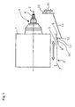
- a rotatably driven about a spindle axis 2 work spindle 3 is arranged, one axial end of a jig 4 for a workpiece, for example in the form of a gear blank or a toothed shaft blank having.
- the first carriage 1 is adjustable along a linear first movement axis between a first position and a second position. The adjusting movement along the first axis of movement parallel to the spindle axis 2 is indicated by a double arrow 5.
- Attached to the first carriage 1 is a schematically indicated cam track 6, which has a first track section 7 parallel to the first movement axis, an adjoining ramp-shaped track section 8 inclined to the first movement axis and an adjoining second track section 9 parallel to the first movement axis ,
- the second track section 9 has a smaller distance to the spindle axis 2 than the first track section 7.
- a schematically indicated second carriage 10 which serves to support a measuring sensor (not shown), is adjustable along a linear second movement axis orthogonal to the first movement axis between a measuring position and a rest position withdrawn from the measuring position.
- the adjustment movement of the second carriage 10 along the second movement axis is indicated by a double arrow 11.
- a lever arrangement which can be pivoted about a pivot axis 12 which is orthogonal to the first and the second movement axis, has a first lever arm 13 and a second lever arm 14.
- the first lever arm 13 extends from the relative to the first carriage 1 and the second carriage 10 stationary pivot axis 12 in the direction of the cam track 6 and is provided at its cam track 6 facing end with a rotatably mounted roller 15, whose axis of rotation parallel to the pivot axis 12 extends.
- the roller 15 is held by a suitable means, for example, a lever assembly with respect to the pivot axis 12 in the clockwise direction with a torsional force stressing spring (not shown), on the cam track 6 in abutment.
- the second lever arm 14 extends from the pivot axis 12 to the second carriage 10 and is hinged thereto so that it follows a pivoting of the second lever arm 14 by a longitudinal direction of the double arrow 11 directed adjusting movement.
- Fig. 1 is the first carriage 1 in its first position, wherein on the jig 4 a machined gear blank (not shown) is clamped.
- the indexing sensor constituting the sensor (not shown) supported on the second carriage 10 is in its measuring position approximating the workpiece, in which the indexing operation is carried out.
- the first carriage 1 is moved by its movement drive (not shown) along the first axis of movement in the direction of the in relation to Fig. 1 shown first position further right second position adjusted.
- the previously applied to the second path section 9 of the cam track 6 roller 15 runs on the in Fig. 1 to the right moving ramp-shaped track section 8.
- first lever arm 13 is pivoted about the pivot axis 12 in the clockwise direction and the second carriage 10 is retracted by the ratio of the lever assembly corresponding adjustment movement of the second lever arm 14 relative to the spindle axis 2 until it passes through the roller 15 through the ramp-shaped path section 8 by the system of the roller 15 has reached certain resting position on the adjoining first path section 7.
- the second carriage 10 with the probe so far away from the spindle axis 2 that a collision is excluded with it as a result of the adjustment movement 5 of the first carriage 1 to the right moving parts.
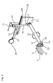
- FIG. 2 illustrated second embodiment also has the in Fig. 1 on the basis of the reference numerals 1 to 11 explained embodiment. However, in Fig. 2 only the adjusting movement 5 of the first carriage 1 following curved path 6 shown.
- the illustration of the second carriage 10 is in Fig. 2 across from Fig. 1 through the presentation its stationary guideway 16, through which it is performed according to its adjusting movement 11 along the second axis of movement, supplemented.
- the holder 17 of the probe on the second carriage 10 and the workpiece 24 indicated.
- the difference from in Fig. 1 illustrated embodiment consists essentially in that the pivot axis 12 'is arranged parallel to the first axis of movement.
- the pivoting movement taking place about the pivot axis 12 'is illustrated by a double arrow 18.
- the pivotal axis 12 'forming rod-shaped part is rotatably mounted at its to the cam track 6 facing axial end 19 in a stationary bearing 20 and at its opposite axial end in a guide track 16 supporting stationary bearing plate 21.
- the first lever arm 13 'extending radially with respect to the pivot axis 12' is arranged, at the free end of which the roller 15 'engaging with the cam track 6 is rotatably mounted.
- the second lever arm 14 ' extends from the axial end 19 opposite axial end of the pivot axis 12' forming rod-shaped part from radially to a mounted on the second carriage 10 part 22, in which an orthogonal to the second axis of movement guide slot is formed.
- This guide slot a fixed to the second lever arm 14 'guide pin is guided.
- the guide slot accommodates the movement component of the pivoting movement of the second lever arm 14 'that is orthogonal to the second movement path, while the component of this pivoting movement parallel to the second movement axis causes a corresponding adjustment movement of the second carriage 10.
- Fig. 1 is also the about the pivot axis 12 'centered torsion spring 23 recognizable, one end of which is supported on the second lever arm 14' and the other end to the stationary bearing plate 21 so that it exerts a torque by which the roller 15 'on the curved path 6 is held in investment.
Landscapes
- Engineering & Computer Science (AREA)
- Mechanical Engineering (AREA)
- Machine Tool Units (AREA)
- A Measuring Device Byusing Mechanical Method (AREA)
- Transmission Devices (AREA)
- Turning (AREA)
Applications Claiming Priority (1)
| Application Number | Priority Date | Filing Date | Title |
|---|---|---|---|
| DE202007012868U DE202007012868U1 (de) | 2007-09-14 | 2007-09-14 | Schlittenanordnung für eine Werkzeugmaschine |
Publications (2)
| Publication Number | Publication Date |
|---|---|
| EP2036645A2 true EP2036645A2 (fr) | 2009-03-18 |
| EP2036645A3 EP2036645A3 (fr) | 2012-05-02 |
Family
ID=38806448
Family Applications (1)
| Application Number | Title | Priority Date | Filing Date |
|---|---|---|---|
| EP08016008A Withdrawn EP2036645A3 (fr) | 2007-09-14 | 2008-09-11 | Agencement de chariot pour une machine-outil |
Country Status (5)
| Country | Link |
|---|---|
| US (1) | US7712227B2 (fr) |
| EP (1) | EP2036645A3 (fr) |
| JP (1) | JP2009066752A (fr) |
| CN (1) | CN101386134B (fr) |
| DE (1) | DE202007012868U1 (fr) |
Families Citing this family (8)
| Publication number | Priority date | Publication date | Assignee | Title |
|---|---|---|---|---|
| US20090174162A1 (en) * | 2007-12-21 | 2009-07-09 | Gass Stephen F | Mobile base for a table saw |
| US8246059B2 (en) * | 2008-02-29 | 2012-08-21 | Sd3, Llc | Mobile base for a table saw |
| EP2483032B1 (fr) * | 2009-10-01 | 2015-09-23 | The Gleason Works | Mécanisme de sonde pour machine-outil |
| TWI399502B (zh) * | 2010-10-07 | 2013-06-21 | Rexon Ind Corp Ltd | 用於加工機具之基座總成 |
| KR101401264B1 (ko) * | 2012-06-27 | 2014-06-02 | 한국생산기술연구원 | 탈착 가능한 프로브 장착 지그 |
| CN106054807B (zh) * | 2016-06-24 | 2017-11-10 | 广汉快速铁路设备有限公司 | 不落轮车床轮对防滑监控系统及其监控方法 |
| CN107097102B (zh) * | 2017-05-03 | 2023-08-01 | 佛山职业技术学院 | 一种传感器夹具 |
| CN110281037B (zh) * | 2019-06-28 | 2021-09-03 | 航天神舟飞行器有限公司 | 一种适用于飞机蒙皮制孔的测量加工执行头 |
Family Cites Families (16)
| Publication number | Priority date | Publication date | Assignee | Title |
|---|---|---|---|---|
| JPS5721224A (en) * | 1980-07-16 | 1982-02-03 | Toyota Motor Corp | Indexing and positioning device of geat tooth chamfering machine |
| DE3638141A1 (de) * | 1986-11-08 | 1988-05-11 | Cima | Abwaelzfraesmaschine mit kontrollvorrichtung der zaehne des sich in bearbeitung befindlichen teils |
| CH672182A5 (fr) * | 1987-06-29 | 1989-10-31 | Meseltron Sa | |
| DE3934056A1 (de) * | 1989-10-12 | 1991-05-08 | Zeiss Carl Fa | Tastkopf fuer koordinatenmessgeraete |
| US5297055A (en) * | 1990-04-20 | 1994-03-22 | The Gleason Works | Multi-functional measurement system |
| DE4204632A1 (de) * | 1990-08-28 | 1993-08-19 | Leitz Messtechnik | Zentriereinrichtung fuer einen mechanischen tastkopf |
| US5273717A (en) * | 1992-09-30 | 1993-12-28 | Eastman Kodak Company | Self-calibrating analyzer aspirator |
| IT1263452B (it) * | 1993-07-01 | 1996-08-05 | Marposs Spa | Comparatore a tampone. |
| JP3874872B2 (ja) * | 1996-05-27 | 2007-01-31 | ヤマザキマザック株式会社 | 主軸頭3軸移動型cnc旋盤 |
| DE19809690A1 (de) * | 1998-03-06 | 1999-09-09 | Zeiss Carl Fa | Koordinatenmeßgerät mit Benutzerführung |
| GB0201845D0 (en) * | 2002-01-26 | 2002-03-13 | Renishaw Plc | Analogue probe |
| GB0215152D0 (en) * | 2002-07-01 | 2002-08-07 | Renishaw Plc | Probe or stylus orientation |
| DE20218352U1 (de) * | 2002-11-26 | 2003-01-23 | Reishauer Ag, Wallisellen | Einzentriervorrichtung zum Ausrichten von vorverzahnten Werkstücken auf Verzahnungsfeinbearbeitungsmaschinen |
| DE60308632T2 (de) * | 2003-01-29 | 2007-08-23 | Tesa Sa | Taststift mit einstellbarer Orientierung |
| GB2417090A (en) * | 2003-04-28 | 2006-02-15 | Stephen James Crampton | CMM arm with exoskeleton |
| JP4759104B2 (ja) * | 2005-08-26 | 2011-08-31 | 株式会社ユネクス | センサ保持装置 |
-
2007
- 2007-09-14 DE DE202007012868U patent/DE202007012868U1/de not_active Expired - Lifetime
-
2008
- 2008-09-08 US US12/231,927 patent/US7712227B2/en not_active Expired - Fee Related
- 2008-09-11 EP EP08016008A patent/EP2036645A3/fr not_active Withdrawn
- 2008-09-12 CN CN2008101609011A patent/CN101386134B/zh not_active Expired - Fee Related
- 2008-09-12 JP JP2008234135A patent/JP2009066752A/ja active Pending
Also Published As
| Publication number | Publication date |
|---|---|
| US20090072117A1 (en) | 2009-03-19 |
| US7712227B2 (en) | 2010-05-11 |
| JP2009066752A (ja) | 2009-04-02 |
| EP2036645A3 (fr) | 2012-05-02 |
| CN101386134B (zh) | 2012-01-11 |
| CN101386134A (zh) | 2009-03-18 |
| DE202007012868U1 (de) | 2007-12-06 |
Similar Documents
| Publication | Publication Date | Title |
|---|---|---|
| EP2036645A2 (fr) | Agencement de chariot pour une machine-outil | |
| DE3322944C2 (de) | Matrizenauswerfer-Vorrichtung für Mehrstufen-Umformmaschinen | |
| DE69708834T2 (de) | Formgesenk von dünnen Blech | |
| DE2353833C3 (de) | Steuereinrichtung für den Schleifschlitten einer Schleifmaschine | |
| DE3017613C2 (fr) | ||
| DE1233696B (de) | Vorrichtung zur selbsttaetigen Zu- und Abfoerderung von Werkstuecken an Werkzeugmaschinen, insbesondere von Kolben an einer Drehbank | |
| DE19722308C1 (de) | Festwalzmaschine für Kurbelwellen | |
| EP1884303B1 (fr) | Procédé destiné à centrer des pièces à usiner tout comme dispositif destiné à la réalisation d'un tel procédé | |
| DE3016047A1 (de) | Umschaltbare biegemaschine | |
| DE2530813A1 (de) | Bearbeitungsvorrichtung fuer kolben | |
| DE4419656C2 (de) | Einrichtung zur Durchmesser- und/oder Rundheitsmessung beim exzentrischen Rundschleifen | |
| EP2218545B1 (fr) | Dispositif et procédé de traitement précis d'une surface de pièce usinée à rotation symétrique | |
| DE1800871B2 (de) | Hon- oder Schleifvorrichtung zur gleicteeitigen Bearbeitung eines eine Mittelbohrung, zwei Stirnflächen und einen charakteristischen Kreis (z.B. Teilkreis oder Mantelfläche) aufweisenden Werkstücks, wie eines Zahnrades oder eines Lagerlaufringes | |
| EP1428612B1 (fr) | Dispositif et procédé de positionnement angulaire de pièces excentriques telles que des villebrequins, par l'intermédiaire de mâchoires montées sur une lunette de centrage | |
| DE2245994A1 (de) | Mehrspindel-drehautomat | |
| DE69416919T2 (de) | Trennmaschine zum automatischen Trennen und Drehen von Rohren | |
| DE69309593T2 (de) | Blattfederspannvorrichtung | |
| DE69000735T2 (de) | Mechanismus mit geringer traegheit zum wiedereinstellen eines werkstueckes in einem pilgerwalzwerk. | |
| DE102022108639B3 (de) | Anschlagsvorrichtung für eine Drehmaschine | |
| EP1413369A1 (fr) | Dispositif et procédé de cintrage d'éléments sous forme de barres | |
| DE1502492B1 (de) | Kopierschleifmaschine | |
| DE10063154A1 (de) | Schmiedepresse mit Stellvorrichtung auf Matrizenseite | |
| DE1577371C3 (de) | Schleifmaschine zum Herstellen einer Anzahl von in Umfangsrichtung verlaufenden Vorsprüngen eines zylindrischen Werkstücks | |
| DE19613169C2 (de) | Vorrichtung zum maschinellen Geradrichten von rotationssymmetrischen Werkstücken | |
| DD268589A3 (de) | Greifer mit schwimmend gelagertem greiferkopf fuer industrieroboter |
Legal Events
| Date | Code | Title | Description |
|---|---|---|---|
| PUAI | Public reference made under article 153(3) epc to a published international application that has entered the european phase |
Free format text: ORIGINAL CODE: 0009012 |
|
| AK | Designated contracting states |
Kind code of ref document: A2 Designated state(s): AT BE BG CH CY CZ DE DK EE ES FI FR GB GR HR HU IE IS IT LI LT LU LV MC MT NL NO PL PT RO SE SI SK TR |
|
| AX | Request for extension of the european patent |
Extension state: AL BA MK RS |
|
| PUAL | Search report despatched |
Free format text: ORIGINAL CODE: 0009013 |
|
| AK | Designated contracting states |
Kind code of ref document: A3 Designated state(s): AT BE BG CH CY CZ DE DK EE ES FI FR GB GR HR HU IE IS IT LI LT LU LV MC MT NL NO PL PT RO SE SI SK TR |
|
| AX | Request for extension of the european patent |
Extension state: AL BA MK RS |
|
| RIC1 | Information provided on ipc code assigned before grant |
Ipc: B23F 19/05 20060101ALI20120326BHEP Ipc: B23F 23/12 20060101ALI20120326BHEP Ipc: B23F 23/08 20060101AFI20120326BHEP |
|
| AKY | No designation fees paid | ||
| REG | Reference to a national code |
Ref country code: DE Ref legal event code: R108 |
|
| REG | Reference to a national code |
Ref country code: DE Ref legal event code: R108 Effective date: 20130109 |
|
| STAA | Information on the status of an ep patent application or granted ep patent |
Free format text: STATUS: THE APPLICATION IS DEEMED TO BE WITHDRAWN |
|
| 18D | Application deemed to be withdrawn |
Effective date: 20121103 |