EP2036710A2 - Rotor für eine Rundlauf-Tablettenpresse - Google Patents
Rotor für eine Rundlauf-Tablettenpresse Download PDFInfo
- Publication number
- EP2036710A2 EP2036710A2 EP08015921A EP08015921A EP2036710A2 EP 2036710 A2 EP2036710 A2 EP 2036710A2 EP 08015921 A EP08015921 A EP 08015921A EP 08015921 A EP08015921 A EP 08015921A EP 2036710 A2 EP2036710 A2 EP 2036710A2
- Authority
- EP
- European Patent Office
- Prior art keywords
- guide
- punch
- sealing ring
- rotor according
- bores
- Prior art date
- Legal status (The legal status is an assumption and is not a legal conclusion. Google has not performed a legal analysis and makes no representation as to the accuracy of the status listed.)
- Granted
Links
- 238000007789 sealing Methods 0.000 claims abstract description 42
- 230000000295 complement effect Effects 0.000 claims abstract description 11
- 229910010293 ceramic material Inorganic materials 0.000 claims description 2
- 239000002184 metal Substances 0.000 claims 1
- 239000000463 material Substances 0.000 description 3
- 239000000919 ceramic Substances 0.000 description 1
- 230000000694 effects Effects 0.000 description 1
- 210000003746 feather Anatomy 0.000 description 1
- 239000000314 lubricant Substances 0.000 description 1
- 238000005461 lubrication Methods 0.000 description 1
- 239000008188 pellet Substances 0.000 description 1
- 239000012254 powdered material Substances 0.000 description 1
- 230000007704 transition Effects 0.000 description 1
Images


Classifications
-
- B—PERFORMING OPERATIONS; TRANSPORTING
- B30—PRESSES
- B30B—PRESSES IN GENERAL
- B30B11/00—Presses specially adapted for forming shaped articles from material in particulate or plastic state, e.g. briquetting presses, tabletting presses
- B30B11/02—Presses specially adapted for forming shaped articles from material in particulate or plastic state, e.g. briquetting presses, tabletting presses using a ram exerting pressure on the material in a moulding space
- B30B11/08—Presses specially adapted for forming shaped articles from material in particulate or plastic state, e.g. briquetting presses, tabletting presses using a ram exerting pressure on the material in a moulding space co-operating with moulds carried by a turntable
-
- B—PERFORMING OPERATIONS; TRANSPORTING
- B30—PRESSES
- B30B—PRESSES IN GENERAL
- B30B15/00—Details of, or accessories for, presses; Auxiliary measures in connection with pressing
- B30B15/0082—Dust eliminating means; Mould or press ram cleaning means
-
- B—PERFORMING OPERATIONS; TRANSPORTING
- B30—PRESSES
- B30B—PRESSES IN GENERAL
- B30B15/00—Details of, or accessories for, presses; Auxiliary measures in connection with pressing
- B30B15/04—Frames; Guides
- B30B15/041—Guides
Definitions
- the invention relates to a rotor for a rotary tablet press according to the preamble of claim 1.
- the typical rotor for a rotary press is composed of a die plate and a lower and an upper punch guide for lower and upper punch, which cooperate with holes in the die plate.
- the rotor is driven by a suitable drive motor about a vertical axis, and the powdery material filled into the die bores by a filling device is compressed by the punches.
- the pressing is done in the so-called printing stations, in each of which at least one upper and one lower pressure roller are arranged, which act on the punch heads.
- the punches are guided by suitable punch curves, including ejection of the pellets by the curves controlling the lower punches.
- Such rotors are about out US 5,004,413 .
- the lower and upper punches usually consist of a shaft, a cooperating with the pressure rollers head and a tool section, which dips into the die holes.
- the mostly cylindrical shaft is guided in corresponding bores of the punch guides. So that the stamps are in the holes do not rotate, it is also known to provide a key which cooperates with a Pespringututut to prevent rotation of the punches.
- the invention has for its object to provide a rotor for a rotary tablet press, in which a simple sealed guide of the ram is made possible.
- the shanks of the ram are provided in cross section with a non-circular profile, and the cross section of the guide holes is complementary.
- the cross section may be a rectangle, a triangle or a somehow rounded polygon.
- the ram shank has smooth surfaces over the circumference, which are easy to seal.
- the guide holes are formed by guide bushes which are arranged in receiving bores of the punch guides.
- the receiving bores can be cylindrical, for example, while the inner cross section of the guide bushes is complementary to the cross section of the ram.
- the inner profile of guide bushes can be produced with high accuracy, without a significant notch effect on the stamp shaft must be feared. Feather springs and associated screws can be omitted.
- the guide bushes are made of ceramic. This eliminates any lubrication of the stamp shank. So-called black spots and stamp eaters also do not occur.
- At least one sealing ring is provided, which is arranged at the upper and / or lower end of the guide bores and has an inner circumference complementary to the shaft profile.
- a sealing ring can simultaneously act as a scraper.
- the sealing ring has a non-circular outer contour and is arranged in a complementary recess of the punch guide. As a result, a rotation of the sealing ring is prevented.
- the sealing ring can sit on the die plate facing the end of the guide holes in a recess of the punch guide.
- the sealing ring on the outer circumference has a radial annular rib which is received positively by a complementary groove in the recess.
- the annular rib may be arranged on a radially yielding portion of the sealing ring.
- a sealing ring is arranged in each case at both ends of the guide bores.
- the guide bushes extend slightly beyond the guide bore at the end facing away from the die plate.
- an embodiment of the invention provides that the sealing ring has a cup-shaped portion which is slipped over the guide bushing.
- the sealing ring has two cone-shaped sealing lips which are spaced apart in the axial direction and extend divergently to the axis of the sealing ring.
- a further embodiment of the invention provides that the punch heads each have a flattening on the sides facing the adjacent punch heads. Due to the non-circular contour of the rotational position of the ram is fixed. If the heads of the ram on opposite sides provided with flats, it can be ensured with respect to the orientation by the cross section of the punch shaft that the flats point respectively in the direction of rotation of the rotor and the adjacent punch head. This makes it possible, the punch heads very close together. The number of can be arranged on a pitch circle ram can therefore be increased.
- a rotor 10 of which in Fig. 1 only a section is shown, has an upper punch guide 12 and a lower punch guide 14 and a die plate 16 between the upper and lower punch guide 12, 14.
- all parts are a one-piece unit. It is understood that it can also be multi-part.
- the die plate may consist of individual segments.
- the upper punch guide 12 has receiving bores 18, and the lower punch guide 14 has receiving bores 20.
- the punch guides 12, 14 lead in pairs upper punch 22 and lower punch 24, which cooperate with die holes 26 of the die plate 16 to compress powdered material in the die holes 26.
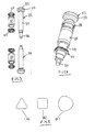
- FIG. 3 Upper and lower punches 22, 24 and guide bushings 28, 30 are shown.
- the press punches 22, 24 have a head 32, a shank 34 and a tool section 36. Only the tool portion 36 cooperates with the die bore 26 (hereinafter only the upper punch 22 is treated, the lower punch 24 is to be considered in the same way).
- the head 32 is substantially standardized in its top. It cooperates with pressure rollers, not shown, which press the upper punch 22 into the die bore 26 against the pressing material.
- the shaft 34 is of non-circular cross-section.
- Fig. 5 Cross-sectional shapes are shown by way of example.
- Fig. 5a shows a triangular
- Fig. 5c a cross section composed of three sections of a circle, the transitions being rounded.
- the guide bushings 28, 30, which may consist of ceramic material and are glued into the receiving bores 18 and 20 respectively, have a cross-section of the shafts 34 complementary cross-section.
- the described cross sections therefore determine the rotational position of the punches 22, 24 in the punch guide 12 and 14, respectively.
- Each punch 22, 24 or each guide bush 28 and 30 is associated with an upper sealing ring 38 and a lower sealing ring 40. In 6 and 7 the sealing ring 40 is shown more clearly.
- the sealing ring has an inner contour that is approximately contoured Fig. 5c equivalent.
- the outer contour is square with rounded corners.
- the sealing ring 40 also has an annular rib 42, which is integrally formed on a radially yielding portion 44 of the sealing ring.
- the annular rib 42 may, as shown more clearly in FIG Fig. 8 is shown, in a groove 46 of the receiving bore 18, which is cylindrical, are used.
- the non-circular shape of the sealing ring 40 on the outer circumference which corresponds to a corresponding shape of the receiving groove 46, prevents rotation of the seal 40 in the recess in which it is seated at the end of the receiving bore 18 in the stamp guide 12.
- a further seal 52 is pot-shaped on the side facing the guide bushing 28 and engages over the guide bushing 28, which protrudes beyond the upper end of the receiving bore 18 by a certain amount. Since also the outer circumference of the guide bush 28 is out of round, prevents the profile, the seal 52 can rotate.
- Fig. 4 the guide bush 28 and the sealing rings 38, 40 are arranged on the punch 22. However, the sealing rings 38, 40 are shown in an exploded position to better recognize their contour.
- the punches 22, 24 have opposite flats 56 on the heads 32.
- the flattenings are as if from Fig. 1 results, in each case to the adjacent ram out. The punches can therefore be brought together very close.
Landscapes
- Engineering & Computer Science (AREA)
- Mechanical Engineering (AREA)
- Press-Shaping Or Shaping Using Conveyers (AREA)
- Medical Preparation Storing Or Oral Administration Devices (AREA)
- Processing And Handling Of Plastics And Other Materials For Molding In General (AREA)
- Medicinal Preparation (AREA)
Abstract
Description
- Die Erfindung bezieht sich auf einen Rotor für eine Rundlauf-Tablettenpresse nach dem Oberbegriff des Anspruchs 1.
- Der typische Rotor für eine Rundlaufpresse setzt sich zusammen aus einer Matrizenscheibe und einer unteren und einer oberen Stempelführung für Unter- und Oberstempel, welche mit Bohrungen in der Matrizenscheibe zusammenwirken. Der Rotor wird von einem geeigneten Antriebsmotor um eine vertikale Achse angetrieben, und das von einer Fülleinrichtung in die Matrizenbohrungen eingefüllte pulverförmige Material wird von den Stempeln zusammengepreßt. Das Verpressen geschieht in den sogenannten Druckstationen, in denen jeweils mindestens eine obere und eine untere Druckrolle angeordnet sind, die auf die Stempelköpfe einwirken. In den übrigen Drehphasen werden die Stempel von geeigneten Stempelkurven geführt, u.a. zum Ausstoßen der Presslinge durch die die Unterstempel steuernden Kurven. Derartige Rotoren sind etwa aus
US 5 004 413 ,DE 101 59 114 A1 oderDE 10 2004 040 163 B3 bekannt geworden. - Die Unter- und Oberstempel bestehen üblicherweise aus einem Schaft, einem mit den Druckrollen zusammenwirkenden Kopf und einem Werkzeugabschnitt, der in die Matrizenbohrungen eintaucht. Der zumeist zylindrische Schaft wird in entsprechenden Bohrungen der Stempelführungen geführt. Damit die Stempel sich in den Bohrungen nicht drehen, ist auch bekannt, eine Paßfeder vorzusehen, die mit einer Peßfedernut zusammenwirkt, um eine Drehung der Stempel zu verhindern.
- Um die Führungseigenschaft nicht zu beeinträchtigen, ist auch bekannt, Dichtungen vorzusehen, welche verhindern, daß Preßmaterial zwischen Führungsbohrung und Stempelschaft gelangt und Schmiermittel austritt. Die Abdichtung im Bereich einer Paßfedernut ist nicht möglich. Somit darf der Stempelschaft nicht im Bereich der Paßfedernut durch eine Dichtung bewegt werden.
- Der Erfindung liegt die Aufgabe zugrunde, einen Rotor für eine Rundlauf-Tablettenpresse zu schaffen, bei dem eine einfache abgedichtete Führung der Preßstempel ermöglicht ist.
- Diese Aufgabe wird durch die Merkmale des Patentanspruchs 1 gelöst.
- Bei der Erfindung sind die Schäfte der Preßstempel im Querschnitt mit einem unrunden Profil versehen, und der Querschnitt der Führungsbohrungen ist komplementär. So kann z.B. der Querschnitt ein Rechteck, ein Dreieck oder ein irgendwie abgerundetes Polygon sein. Mithin weist der Preßstempelschaft über den Umfang glatte Flächen auf, die leicht abzudichten sind.
- Nach einer Ausgestaltung der Erfindung ist vorgesehen, daß die Führungsbohrungen von Führungsbuchsen gebildet sind, die in Aufnahmebohrungen der Stempelführungen angeordnet sind. Die Aufnahmebohrungen können z.B. zylindrisch sein, während der Innenquerschnitt der Führungsbuchsen komplementär zum Querschnitt der Preßstempel ist. Das Innenprofil von Führungsbuchsen läßt sich mit hoher Genauigkeit herstellen, ohne daß eine nennenswerte Kerbwirkung am Stempelschaft befürchtet werden muß. Paßfedern und zugehörige Schrauben können entfallen. Vorzugsweise sind die Führungsbuchsen aus Keramik. Dadurch entfällt jegliche Schmierung des Stempelschaftes. Sogenannte Black-Spots und Stempelfresser treten ebenfalls nicht auf.
- Nach einer weiteren Ausgestaltung der Erfindung ist mindestens ein Dichtring vorgesehen, der am oberen und/oder unteren Ende der Führungsbohrungen angeordnet ist und einen zum Schaftprofil komplementären Innenumfang aufweist. Ein derartiger Dichtring kann gleichzeitig als Abstreifer fungieren.
- Nach einer weiteren Ausgestaltung der Erfindung weist der Dichtring eine unrunde Außenkontur auf und ist in einer komplementären Ausnehmung der Stempelführung angeordnet. Dadurch wird eine Verdrehung des Dichtrings verhindert.
- Der Dichtring kann an dem der Matrizenscheibe zugewandten Ende der Führungsbohrungen in einer Ausnehmung der Stempelführung sitzen. Hierzu kann nach einer weiteren Ausgestaltung der Erfindung vorgesehen sein, daß der Dichtring am Außenumfang eine radiale Ringrippe aufweist, die von einer komplementären Nut in der Ausnehmung formschlüssig aufgenommen ist. Die Ringrippe kann an einem radial nachgebenden Abschnitt des Dichtrings angeordnet sein. Vorzugsweise ist an beiden Enden der Führungsbohrungen jeweils ein Dichtring angeordnet.
- Nach einer weiteren Ausgestaltung der Erfindung erstrecken sich die Führungsbuchsen an dem der Matrizenscheibe abgewandten Ende etwas über die Führungsbohrung hinaus. Für diesen Fall sieht eine Ausgestaltung der Erfindung vor, daß der Dichtring einen topfförmigen Abschnitt hat, der über die Führungsbuchse gestülpt ist.
- Vorzugsweise hat der Dichtring zwei in Achsrichtung beabstandete kegelringförmige Dichtlippen, die divergierend sich zur Achse des Dichtrings hin erstrecken.
- Schließlich sieht eine weitere Ausgestaltung der Erfindung vor, daß die Stempelköpfe auf den den benachbarten Stempelköpfen zugewandten Seiten jeweils eine Abflachung aufweisen. Durch die unrunde Kontur liegt die Drehlage der Preßstempel fest. Werden die Köpfe der Preßstempel auf einander gegenüberliegenden Seiten mit Abflachungen versehen, kann in bezug auf die Orientierung durch den Querschnitt des Stempelschaftes dafür gesorgt werden, daß die Abflachungen jeweils in Drehrichtung des Rotors weisen bzw. zum benachbarten Stempelkopf hin. Dadurch ist es möglich, die Stempelköpfe sehr nahe zusammenzubringen. Die Anzahl der auf einem Teilkreis anordbaren Preßstempel kann daher erhöht werden.
- Die Erfindung wird nachfolgend anhand von Ausführungsbeispielen näher erläutert.
- Fig. 1
- zeigt einen Abschnitt eines Rotors einer Tablettenpresse mit Merkmalen der Erfindung in perspektivischer Ansicht.
- Fig. 2
- zeigt einen Schnitt durch die Anordnung nach
Fig. 1 entlang der Linie 2-2. - Fig. 3
- zeigt perspektivisch auseinandergezogen einen unteren und einen oberen Stempel mit Führungsbuchse und Dichtringen.
- Fig. 4
- zeigt perspektivisch den Zusammenbau des Oberstempels mit Buchse und Dichtringen nach
Fig. 3 . - Fig. 5a-c
- zeigt verschiedene Querschnitte für Stempelschäfte.
- Fig. 6
- zeigt die Draufsicht auf einen Dichtring gemäß
Fig. 3 . - Fig. 7
- zeigt einen Schnitt durch den Dichtring nach
Fig. 6 entlang der Linie 7-7. - Fig. 8
- zeigt vergrößert teilweise den Oberstempel nach
Fig. 1 mit Führungsbuchse und Dichtringen. - Ein Rotor 10, von dem in
Fig. 1 lediglich ein Ausschnitt gezeigt ist, weist eine obere Stempelführung 12 und eine untere Stempelführung 14 auf sowie eine Matrizenscheibe 16 zwischen oberer und unterer Stempelführung 12, 14. Im gezeigten Fall sind alle Teile eine einteilige Einheit. Es versteht sich, daß sie auch mehrteilig sein kann. Insbesondere kann die Matrizenscheibe aus einzelnen Segmenten bestehen. - Die obere Stempelführung 12 weist Aufnahmebohrungen 18 auf, und die untere Stempelführung 14 weist Aufnahmebohrungen 20 auf. Die Stempelführungen 12, 14 führen paarweise Oberstempel 22 und Unterstempel 24, welche mit Matrizenbohrungen 26 der Matrizenscheibe 16 zusammenwirken, um pulverförmiges Material in den Matrizenbohrungen 26 zu verpressen.
- Wie insbesondere in
Fig. 2 zu erkennen, nehmen die Aufnahmebohrungen 18, 20 Führungsbuchsen 28, 30 auf. InFig. 3 sind Ober- und Unterstempel 22, 24 und Führungsbuchsen 28, 30 dargestellt. Die Preßstempel 22, 24 weisen einen Kopf 32, einen Schaft 34 und einen Werkzeugabschnitt 36 auf. Nur der Werkzeugabschnitt 36 wirkt mit der Matrizenbohrung 26 zusammen (nachfolgend wird nur der Oberstempel 22 behandelt, wobei der Unterstempel 24 in gleicher Weise zu betrachten ist). Der Kopf 32 ist in seiner Oberseite im wesentlichen standardisiert. Er wirkt mit nicht gezeigten Druckrollen zusammen, welche den Oberstempel 22 in die Matrizenbohrung 26 hinein gegen das Preßmaterial pressen. Der Schaft 34 ist von unrundem Querschnitt. InFig. 5 sind Querschnittsformen beispielhaft dargestellt.Fig. 5a zeigt einen dreieckigen,Fig. 5b einen quadratischen undFig. 5c einen aus drei Kreisabschnitten zusammengesetzten Querschnitt, wobei die Übergänge gerundet sind. Die Führungsbuchsen 28, 30, die aus keramischem Material bestehen können und in die Aufnahmebohrungen 18 bzw. 20 eingeklebt sind, haben einen zum Querschnitt der Schäfte 34 komplementären Querschnitt. Die beschriebenen Querschnitte legen daher die Drehlage der Stempel 22, 24 in der Stempelführung 12 bzw. 14 fest. Jedem Stempel 22, 24 bzw. jeder Führungsbuchse 28 bzw. 30 ist ein oberer Dichtring 38 und ein unterer Dichtring 40 zugeordnet. InFig. 6 und 7 ist der Dichtring 40 deutlicher dargestellt. Der Dichtring hat eine Innenkontur, die etwa der Kontur nachFig. 5c entspricht. Die Außenkontur ist quadratisch mit abgerundeten Ecken. Der Dichtring 40 weist außerdem eine Ringrippe 42 auf, welche an einem radial nachgebenden Abschnitt 44 des Dichtrings angeformt ist. Die Ringrippe 42 kann, wie dies deutlicher inFig. 8 dargestellt ist, in eine Nut 46 der Aufnahmebohrung 18, die zylindrisch ist, eingesetzt werden. - Wie ferner in
Fig. 7 zu erkennen, weist der Dichtring 40 an der Innenseite zwei konische Dichtlippen 48, 50 auf, die sich divergierend schräg in Richtung Achse des Dichtrings 40 erstrecken und mit dem Schaft 34 in Eingriff sind, wie dies inFig. 8 dargestellt ist. - Die unrunde Form des Dichtrings 40 am Außenumfang, der eine entsprechende Form der Aufnahmenut 46 entspricht, verhindert eine Verdrehung der Dichtung 40 in der Ausnehmung, in der sie am Ende der Aufnahmebohrung 18 in der Stempelfiihrung 12 einsitzt.
- Eine weitere Dichtung 52 ist auf der der Führungsbuchse 28 zugekehrten Seite topfartig und übergreift die Führungsbuchse 28, die um ein gewisses Maß über das obere Ende der Aufnahmebohrung 18 hinaussteht. Da auch der Außenumfang der Führungsbuchse 28 unrund ist, verhindert das Profil, das sich die Dichtung 52 verdrehen kann.
- In
Fig. 4 sind die Führungsbuchse 28 und die Dichtringe 38, 40 auf dem Stempel 22 angeordnet. Die Dichtringe 38, 40 sind jedoch in einer auseinandergezogenen Position gezeigt, um ihre Kontur besser erkennen zu können. - Wie schließlich aus einigen Figuren deutlich wird, weisen die Stempel 22, 24 an den Köpfen 32 gegenüberliegende Abflachungen 56 auf. Die Abflachungen liegen, wie sich aus
Fig. 1 ergibt, jeweils zum benachbarten Preßstempel hin. Die Preßstempel können daher sehr nahe zusammengebracht werden.
Claims (12)
- Rotor für eine Rundlauf-Tablettenpresse, der eine obere und eine untere Stempelführung für Ober- und Unterstempel aufweist, die mit Bohrungen einer zwischen Ober- und Unterstempelfiihrung angeordneten Matrizenscheibe zusammenwirken, wobei die Stempel Schäfte aufweisen, die mittels einer Dichtungsanordnung abgedichtet in Führungsbohrungen der Stempelführungen axial bewegbar sind und wobei zwischen den Schäften und den Führungsbohrungen Mittel wirken, die eine Drehung der Preßstempel in den Führungsbohrungen verhindern, dadurch gekennzeichnet, daß die Schäfte (34) im Querschnitt ein unrundes Profil aufweisen und der Querschnitt der Führungsbohrungen komplementär ist.
- Rotor nach Anspruch 1, dadurch gekennzeichnet, daß die Führungsbohrungen von Führungsbuchsen (28, 30) gebildet sind, die in Aufnahmebohrungen (18, 20) der Stempelführungen (12, 14) angeordnet sind.
- Rotor nach Anspruch 2, dadurch gekennzeichnet, daß die Führungsbuchsen (28, 30) aus keramischem Material oder Hartmetall geformt sind.
- Rotor nach einem der Ansprüche 1 bis 3, dadurch gekennzeichnet, daß die Dichtungsanordnung mindestens einen Dichtring aufweist, der am oberen und/oder unteren Ende der Führungsbohrungen angeordnet ist und einen zum Schaftprofil komplementären Innenumfang aufweist.
- Rotor nach Anspruch 4, dadurch gekennzeichnet, daß der Dichtring (40) eine unrunde Außenkontur aufweist und in einer komplementären Ausnehmung (54) der Stempelführung sitzt.
- Rotor nach Anspruch 5, dadurch gekennzeichnet, daß der Dichtring an dem der Matrizenscheibe zugewandten Ende der Führungsbohrungen in einer Ausnehmung der Stempelführung angeordnet ist.
- Rotor nach Anspruch 6, dadurch gekennzeichnet, daß der Dichtring (40) am Außenumfang eine Ringrippe (42) aufweist, die von einer komplementären Nut (46) in der Ausnehmung (54) formschlüssig aufgenommen ist.
- Rotor nach Anspruch 7, dadurch gekennzeichnet, daß die Ringrippe (42) an einem radial nachgebenden Abschnitt (44) des Dichtrings (40) angeordnet ist.
- Rotor nach einem der Ansprüche 4 bis 8, dadurch gekennzeichnet, daß jeweils ein Dichtring (38, 40) an beiden Enden der Führungsbohrungen angeordnet ist.
- Rotor nach Anspruch 2 und einem der Ansprüche 4 bis 9, dadurch gekennzeichnet, daß der Dichtring (38) einen topfförmigen Abschnitt hat, der an dem der Matrizenscheibe (16) abgewandten Ende über die Führungsbuchse (28, 30) gestülpt ist, die etwas über die Stempelführung (12, 14) hinaussteht.
- Rotor nach einem der Ansprüche 4 bis 10, dadurch gekennzeichnet, daß der Dichtring (40) zwei in Achsrichtung beabstandete kegelringförmige Dichtlippen (48, 50) aufweist, die divergierend sich zur Achse des Dichtrings (40) erstrecken.
- Rotor nach einem der Ansprüche 1 bis 11, dadurch gekennzeichnet, daß die Stempelköpfe (32) auf der den benachbarten Stempelköpfen zugewandten Seite jeweils eine Abflachung (56) aufweisen.
Applications Claiming Priority (1)
| Application Number | Priority Date | Filing Date | Title |
|---|---|---|---|
| DE102007043584A DE102007043584B4 (de) | 2007-09-13 | 2007-09-13 | Rotor für eine Rundlauf-Tablettenpresse |
Publications (3)
| Publication Number | Publication Date |
|---|---|
| EP2036710A2 true EP2036710A2 (de) | 2009-03-18 |
| EP2036710A3 EP2036710A3 (de) | 2011-03-09 |
| EP2036710B1 EP2036710B1 (de) | 2016-07-20 |
Family
ID=39885146
Family Applications (1)
| Application Number | Title | Priority Date | Filing Date |
|---|---|---|---|
| EP08015921.3A Active EP2036710B1 (de) | 2007-09-13 | 2008-09-10 | Rotor für eine Rundlauf-Tablettenpresse |
Country Status (3)
| Country | Link |
|---|---|
| US (1) | US7641465B2 (de) |
| EP (1) | EP2036710B1 (de) |
| DE (1) | DE102007043584B4 (de) |
Families Citing this family (5)
| Publication number | Priority date | Publication date | Assignee | Title |
|---|---|---|---|---|
| US7850884B2 (en) * | 2009-04-01 | 2010-12-14 | The Gillette Company | Method of compacting material |
| US7959837B2 (en) * | 2009-04-01 | 2011-06-14 | The Gillette Company | Method of compacting material |
| DE102011101288B4 (de) * | 2011-05-10 | 2013-11-14 | Fette Compacting Gmbh | Verfahren zum Betrieb einer Anlage zur Herstellung von Tabletten sowie entsprechende Anlage |
| DE102011101289B4 (de) * | 2011-05-10 | 2013-11-14 | Fette Compacting Gmbh | Stempelanordnung für eine Presse und Presse sowie Rundläuferpresse |
| USD836142S1 (en) * | 2015-06-30 | 2018-12-18 | Iro Co., Ltd. | Punch of tableting machine |
Citations (3)
| Publication number | Priority date | Publication date | Assignee | Title |
|---|---|---|---|---|
| US5004413A (en) | 1988-12-03 | 1991-04-02 | Manesty Machines Limited | Tablet making machines |
| DE10159114A1 (de) | 2001-12-01 | 2003-06-18 | Fette Wilhelm Gmbh | Rotor für eine Tablettenpresse |
| DE102004040163B3 (de) | 2004-08-19 | 2006-05-04 | Fette Gmbh | Rundläufertablettenpresse |
Family Cites Families (13)
| Publication number | Priority date | Publication date | Assignee | Title |
|---|---|---|---|---|
| US2068619A (en) * | 1935-09-13 | 1937-01-19 | Stokes Machine Co | Tablet-making machine |
| US2875797A (en) * | 1954-06-02 | 1959-03-03 | Changewood Corp | Hydraulic molding press |
| US3318265A (en) * | 1964-03-16 | 1967-05-09 | Abbott Lab | Tablet punch assembly |
| DE1934382U (de) * | 1965-12-13 | 1966-03-10 | Festo Maschf Stoll G | Kolbenstange mit fuehrung fuer einen in einem pneumatischen oder hydraulischen druckmittel gefuellten arbeitszylinder hin und her gehenden kolben. |
| DE2424655C3 (de) * | 1974-05-21 | 1979-06-28 | Kilian & Co Gmbh, 5000 Koeln | Rundlauf tablettenpresse |
| US4298563A (en) * | 1978-10-19 | 1981-11-03 | Ptx-Pentronix, Inc. | Apparatus and method for compacting prismatic or pyramidal articles from powder material |
| WO2000056534A1 (de) * | 1999-03-18 | 2000-09-28 | Korsch Pressen Ag | Rundlaufpresse mit auswechselbaren einsatzstempeln |
| DE19963263C2 (de) * | 1999-03-18 | 2002-05-16 | Korsch Pressen Ag | Rundlaufpresse mit auswechselbaren Einsatzstempeln |
| DE20010641U1 (de) * | 2000-06-15 | 2000-08-31 | Wilhelm Fette Gmbh, 21493 Schwarzenbek | Stempel für Rundlaufpresse |
| DE10064640C2 (de) * | 2000-12-22 | 2003-01-09 | Henkel Kgaa | Tablettenpreßstempel-Anordnung |
| DE20205508U1 (de) * | 2002-04-09 | 2002-07-04 | KILIAN GmbH & Co. KG, 50735 Köln | Rundlauf-Tablettenpresse mit Stempeldichtungselement und Stempeldichtungselement |
| DE20304981U1 (de) * | 2003-03-26 | 2004-08-05 | Kilian Gmbh & Co. Kg | Tablettenpresse und Ölfang- und/oder Dichtelement zur Verwendung an Tablettenpressen |
| JP2006212702A (ja) * | 2005-01-05 | 2006-08-17 | Kikusui Seisakusho Ltd | 粉末圧縮成形機 |
-
2007
- 2007-09-13 DE DE102007043584A patent/DE102007043584B4/de not_active Expired - Fee Related
-
2008
- 2008-09-10 EP EP08015921.3A patent/EP2036710B1/de active Active
- 2008-09-11 US US12/208,933 patent/US7641465B2/en active Active
Patent Citations (3)
| Publication number | Priority date | Publication date | Assignee | Title |
|---|---|---|---|---|
| US5004413A (en) | 1988-12-03 | 1991-04-02 | Manesty Machines Limited | Tablet making machines |
| DE10159114A1 (de) | 2001-12-01 | 2003-06-18 | Fette Wilhelm Gmbh | Rotor für eine Tablettenpresse |
| DE102004040163B3 (de) | 2004-08-19 | 2006-05-04 | Fette Gmbh | Rundläufertablettenpresse |
Also Published As
| Publication number | Publication date |
|---|---|
| US7641465B2 (en) | 2010-01-05 |
| US20090074901A1 (en) | 2009-03-19 |
| EP2036710B1 (de) | 2016-07-20 |
| DE102007043584B4 (de) | 2010-04-15 |
| EP2036710A3 (de) | 2011-03-09 |
| DE102007043584A1 (de) | 2009-03-19 |
Similar Documents
| Publication | Publication Date | Title |
|---|---|---|
| EP1755858B1 (de) | Schliesseinheit mit doppelkurbelantrieb | |
| EP1843891B1 (de) | Matrizenscheibe für rundlauf -tablettenpresse und rundlauf -tablettenpresse | |
| EP3785853B1 (de) | Schraubstock | |
| EP2036710B1 (de) | Rotor für eine Rundlauf-Tablettenpresse | |
| EP2082867B1 (de) | Tablettenpresse | |
| EP1316411B1 (de) | Rotor für eine Tablettenpresse | |
| EP2065175B1 (de) | Rundlaufpresse | |
| DE10260110B4 (de) | Vorrichtung zum Stanzen | |
| EP0540964A1 (de) | Messerhalter für Längsschnittstationen an Papierverarbeitungsmaschinen | |
| DE4430897A1 (de) | Rundschaltvorrichtung | |
| DE102007043582B3 (de) | Rotor für eine Rundlauf-Tablettenpresse | |
| EP0436792A2 (de) | Presse zur Herstellung masshaltiger Presslinge aus pulverförmigem Material | |
| EP2241441B1 (de) | Vorrichtung zum Bearbeiten einer Materialbahn zwischen zwei gegenläufig antreibbaren Arbeitswalzen | |
| EP1165308B1 (de) | Rundlaufpresse mit auswechselbaren einsatzstempeln | |
| DE19963263C2 (de) | Rundlaufpresse mit auswechselbaren Einsatzstempeln | |
| DE3029767C2 (de) | Pressenkopf für Teigwarenpresse | |
| EP1321180A2 (de) | Innenmischer | |
| DE2450973A1 (de) | Vorrichtung zur vollautomatischen hubverstellung bei doppelstaenderpressen mit zweipunktantrieb in sogenannter querwellenausfuehrung | |
| DE10232772B3 (de) | Druckverteilungsring für eine Längsteilanlage | |
| DE102009016781B3 (de) | Stempel für eine Rundläuferpresse und Vorrichtung zum Montieren und Demontieren von Stempeleinsätzen für Stempel in einer Rundläuferpresse | |
| DE2211891C3 (de) | Nibbelmaschine, insbesondere Handnibbelmaschine | |
| EP1423261B1 (de) | Unterstempel für eine tablettiermaschine | |
| DE3034009C2 (de) | Vorrichtung zur Verstellung des Stößelhubes bei Doppelständerpressen mit zwei nebeneinander liegenden Exzenterwellen | |
| DE102005051116B4 (de) | Halteranordnung für Schneideeinrichtungen | |
| DE10225588A1 (de) | Ultraschallschweißanlage |
Legal Events
| Date | Code | Title | Description |
|---|---|---|---|
| PUAI | Public reference made under article 153(3) epc to a published international application that has entered the european phase |
Free format text: ORIGINAL CODE: 0009012 |
|
| AK | Designated contracting states |
Kind code of ref document: A2 Designated state(s): AT BE BG CH CY CZ DE DK EE ES FI FR GB GR HR HU IE IS IT LI LT LU LV MC MT NL NO PL PT RO SE SI SK TR |
|
| AX | Request for extension of the european patent |
Extension state: AL BA MK RS |
|
| PUAL | Search report despatched |
Free format text: ORIGINAL CODE: 0009013 |
|
| AK | Designated contracting states |
Kind code of ref document: A3 Designated state(s): AT BE BG CH CY CZ DE DK EE ES FI FR GB GR HR HU IE IS IT LI LT LU LV MC MT NL NO PL PT RO SE SI SK TR |
|
| AX | Request for extension of the european patent |
Extension state: AL BA MK RS |
|
| 17P | Request for examination filed |
Effective date: 20110305 |
|
| AKX | Designation fees paid |
Designated state(s): BE CH DE FR GB IT LI |
|
| 17Q | First examination report despatched |
Effective date: 20130923 |
|
| GRAP | Despatch of communication of intention to grant a patent |
Free format text: ORIGINAL CODE: EPIDOSNIGR1 |
|
| INTG | Intention to grant announced |
Effective date: 20150714 |
|
| GRAP | Despatch of communication of intention to grant a patent |
Free format text: ORIGINAL CODE: EPIDOSNIGR1 |
|
| INTG | Intention to grant announced |
Effective date: 20160324 |
|
| GRAS | Grant fee paid |
Free format text: ORIGINAL CODE: EPIDOSNIGR3 |
|
| GRAA | (expected) grant |
Free format text: ORIGINAL CODE: 0009210 |
|
| AK | Designated contracting states |
Kind code of ref document: B1 Designated state(s): BE CH DE FR GB IT LI |
|
| REG | Reference to a national code |
Ref country code: GB Ref legal event code: FG4D Free format text: NOT ENGLISH |
|
| REG | Reference to a national code |
Ref country code: CH Ref legal event code: EP |
|
| REG | Reference to a national code |
Ref country code: DE Ref legal event code: R096 Ref document number: 502008014410 Country of ref document: DE |
|
| REG | Reference to a national code |
Ref country code: FR Ref legal event code: PLFP Year of fee payment: 9 |
|
| REG | Reference to a national code |
Ref country code: CH Ref legal event code: NV Representative=s name: ISLER AND PEDRAZZINI AG, CH |
|
| REG | Reference to a national code |
Ref country code: DE Ref legal event code: R097 Ref document number: 502008014410 Country of ref document: DE |
|
| PLBE | No opposition filed within time limit |
Free format text: ORIGINAL CODE: 0009261 |
|
| STAA | Information on the status of an ep patent application or granted ep patent |
Free format text: STATUS: NO OPPOSITION FILED WITHIN TIME LIMIT |
|
| 26N | No opposition filed |
Effective date: 20170421 |
|
| REG | Reference to a national code |
Ref country code: FR Ref legal event code: PLFP Year of fee payment: 10 |
|
| REG | Reference to a national code |
Ref country code: FR Ref legal event code: PLFP Year of fee payment: 11 |
|
| P01 | Opt-out of the competence of the unified patent court (upc) registered |
Effective date: 20230530 |
|
| PGFP | Annual fee paid to national office [announced via postgrant information from national office to epo] |
Ref country code: GB Payment date: 20240923 Year of fee payment: 17 |
|
| PGFP | Annual fee paid to national office [announced via postgrant information from national office to epo] |
Ref country code: BE Payment date: 20240920 Year of fee payment: 17 |
|
| PGFP | Annual fee paid to national office [announced via postgrant information from national office to epo] |
Ref country code: FR Payment date: 20240925 Year of fee payment: 17 |
|
| PGFP | Annual fee paid to national office [announced via postgrant information from national office to epo] |
Ref country code: DE Payment date: 20241107 Year of fee payment: 17 |
|
| PGFP | Annual fee paid to national office [announced via postgrant information from national office to epo] |
Ref country code: IT Payment date: 20240930 Year of fee payment: 17 |
|
| PGFP | Annual fee paid to national office [announced via postgrant information from national office to epo] |
Ref country code: CH Payment date: 20241001 Year of fee payment: 17 |