EP2036739A1 - Dokumentensortierungsvorrichtung mit Multipositionsdraht-Teilerelement - Google Patents
Dokumentensortierungsvorrichtung mit Multipositionsdraht-Teilerelement Download PDFInfo
- Publication number
- EP2036739A1 EP2036739A1 EP08015162A EP08015162A EP2036739A1 EP 2036739 A1 EP2036739 A1 EP 2036739A1 EP 08015162 A EP08015162 A EP 08015162A EP 08015162 A EP08015162 A EP 08015162A EP 2036739 A1 EP2036739 A1 EP 2036739A1
- Authority
- EP
- European Patent Office
- Prior art keywords
- side rail
- members
- wire divider
- rail members
- sorting apparatus
- Prior art date
- Legal status (The legal status is an assumption and is not a legal conclusion. Google has not performed a legal analysis and makes no representation as to the accuracy of the status listed.)
- Withdrawn
Links
- 210000003462 vein Anatomy 0.000 abstract description 7
- 239000002184 metal Substances 0.000 description 7
- 239000000463 material Substances 0.000 description 4
- 238000003780 insertion Methods 0.000 description 3
- 230000037431 insertion Effects 0.000 description 3
- 239000011094 fiberboard Substances 0.000 description 2
- 238000002347 injection Methods 0.000 description 2
- 239000007924 injection Substances 0.000 description 2
- 239000002991 molded plastic Substances 0.000 description 2
- 239000000123 paper Substances 0.000 description 2
- 239000002985 plastic film Substances 0.000 description 2
- 239000011347 resin Substances 0.000 description 2
- 229920005989 resin Polymers 0.000 description 2
- 230000000717 retained effect Effects 0.000 description 2
- 239000005060 rubber Substances 0.000 description 2
- 230000003068 static effect Effects 0.000 description 2
- 239000002023 wood Substances 0.000 description 2
- 239000000853 adhesive Substances 0.000 description 1
- 230000001070 adhesive effect Effects 0.000 description 1
- 238000005452 bending Methods 0.000 description 1
- 230000000295 complement effect Effects 0.000 description 1
- 238000002788 crimping Methods 0.000 description 1
- 238000004519 manufacturing process Methods 0.000 description 1
- 238000012986 modification Methods 0.000 description 1
- 230000004048 modification Effects 0.000 description 1
- 238000005192 partition Methods 0.000 description 1
- 238000006748 scratching Methods 0.000 description 1
- 230000002393 scratching effect Effects 0.000 description 1
- 238000003860 storage Methods 0.000 description 1
- 238000003466 welding Methods 0.000 description 1
Images


Classifications
-
- B—PERFORMING OPERATIONS; TRANSPORTING
- B42—BOOKBINDING; ALBUMS; FILES; SPECIAL PRINTED MATTER
- B42F—SHEETS TEMPORARILY ATTACHED TOGETHER; FILING APPLIANCES; FILE CARDS; INDEXING
- B42F17/00—Card-filing arrangements, e.g. card indexes or catalogues or filing cabinets
- B42F17/02—Card-filing arrangements, e.g. card indexes or catalogues or filing cabinets in which the cards are stored substantially at right angles to the bottom of their containers
- B42F17/08—Construction of the containers, e.g. trays or drawers
- B42F17/12—Dividing means
Definitions
- This disclosure relates generally to document organizational devices and, more particularly, to a desktop sorting device for file folders, envelopes, letters, photographs, and other documents having a plurality of regions for supporting and retaining documents, wherein the regions are separated from one another by divider members and the divider members are movable among a plurality of positions to facilitate access a desired one of the regions to view documents, add documents to, or retrieve documents from the desired region of the sorting device.
- Document file organizers are typically static in use and are designed to hold papers and file folders within a vertical, horizontal or angled linear pattern of dividers or sorting veins.
- the dividers are typically parallel to one another to keep the folders in an organized line and to prevent the folders from opening or to prevent paper documents from fanning or falling over.
- Such static document dividers prevent users from viewing the contents of stored documents or files without first removing the contents from between the dividers.
- Existing document sorting organizers having pivoting sorting veins offer the ability to view documents stored between the sorting veins in desired segments of the organizers.
- the sorting veins of such existing organizers are difficult or impossible for the consumer to remove, as may be desired for storage of, e.g., thick files.
- the sorting veins of these existing organizers are not securable in a vertical orientation.
- a document sorting apparatus of the present disclosure has a plurality of discrete regions for supporting and retaining documents.
- the regions are separated from one another by movable wire divider members, which serve both to support documents in a particular region and to segregate or partition off documents in adjacent regions from one another.
- Each of the wire divider members is preferably securable in a plurality of positions to facilitate access to a desired one of the regions to view documents, add documents to, or retrieve documents from the desired region of the sorting device.
- Each of the wire divider members preferably forms an inverted U-shape (which could be a block-U or inverted rounded-U shape), with inverted block-question mark-shaped portions at their lower ends that point inwardly toward one another.
- Two spaced-apart parallel rail members define the sides of a base of the document sorting apparatus.
- Each of the side rail members has a plurality of apertures spaced in a linear fashion along the length of the rail member.
- Each of the apertures in one of the rail members is aligned with a corresponding aperture in the other rail member.
- a horizontal end segment at the bottom of the inverted question mark-shaped portion is pivotably received in one of apertures.
- Each of the side rail members preferably includes a laterally-extending projection above each of the apertures.
- Each of the laterally-extending projections includes a vertically-extending concave depression, i.e. a vertically-oriented dip bounded by a pair of ridges or bumps.
- the ridges of the laterally-extending projections project away from an outer surface of the rail members a sufficient distance to interfere with, but not completely prevent, movement of the wire divider members from one position to another.
- the vertically-extending concave depression of the laterally-extending projection accepts a segment of the block-question mark-shaped portion of the wire divider member that extends orthogonal to the horizontal end segment.
- the ridges bounding the concave depression serve to secure the wire divider member in a vertical orientation.
- each of the side rail members includes an elongate upper lip along a top edge of the side rail member, extending substantially the length of the side rail member, and in a direction toward the opposing side rail member.
- the elongate upper lips along the top edge of the side rail members serve as stops or rests for a second horizontal segment of each of the inverted question mark-shaped portions of the wire divider members, the second horizontal segment extending parallel to the horizontal end segment, supporting the wire divider member in either a rearwardly-inclined position or a forwardly-inclined position.
- Each of the wire divider members are preferably removable from the base of the document sorting apparatus by the user.
- the ability to remove individual wire divider members provides convenient customizability, so as to increase the space between two adjacent wire divider members and accommodate relatively thick documents, files or the like.
- the wire divider members may be permanently secured to the base of the document sorting apparatus.
- the wire divider members have sufficient elasticity or flexing characteristics to enable them to be stretched for purposes of insertion of the horizontal end segments into the corresponding apertures in the side rails, then relax or recoil to a position wherein the horizontal end segments are retained in engagement with the side rails.
- the side rail members may be separated from one another by one or more flexible elements that allow the side rail members to be compressed toward one another so as to accept the horizontal end segments of inflexible wire divider members in the apertures of the side rails.
- Various materials may be used in the manufacture of the base of the document sorting apparatus, including but not limited to bent sheet metal, injection molded plastic, wood or fiber board, fabricated plastic sheet stock, formed metal mesh with metal trim, cold-cast resin, rubber or a combination of materials.
- FIG. 1 is a perspective view of a document sorting apparatus of the present disclosure
- FIG. 2 is a side plan view of the document sorting apparatus shown in FIG. 1 ;
- FIG. 3 is a front plan view of the document sorting apparatus shown in FIG. 1 ;
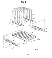
- FIG. 4 is a perspective view of the document sorting apparatus of FIG. 1 , having an alternate floor member;
- FIG. 5 is a top view of the document sorting apparatus shown in FIG. 4 ;
- FIG. 6 is a bottom view of the document sorting apparatus shown in FIG. 4 ;
- FIG. 7 is a left side plan view of the document sorting apparatus shown in FIG. 1 , with all of the wire divider members shown in a rearwardly-inclined orientation;
- FIG. 8 is a right side plan view of the document sorting apparatus shown in FIG. 1 , with all of the wire divider members shown in a rearwardly-inclined orientation;
- FIG. 9 is an exploded view of a document sorting apparatus of the present disclosure.
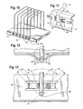
- FIG. 10 is a perspective view of a document sorting apparatus of the present disclosure having lateral projections on side rail members thereof;
- FIG. 11 is an enlarged perspective view of the area of FIG. 10 designated by “ Fig. 11/13 ";
- FIG. 12 is a cross-sectional view taken along lines 12-12 of FIG. 11 , with the wire divider member shown in phantom lines in forwardly-inclined and rearwardly-inclined orientations;
- FIG. 13 is an enlarged side plan view of the area of FIG. 10 designated by " Fig. 11/13 ";
- FIG. 14 is a perspective view of an underside of a base of the sorting apparatus of FIG. 1 ;
- FIG. 15 is a perspective view of a side rail member of the sorting apparatus of FIG. 1 ;
- FIG. 16 is an end view of the side rail member of FIG. 15 ;
- FIG. 17 is a perspective view of a second embodiment of a document sorting apparatus of the present disclosure.
- FIG. 18 is a perspective view of a third embodiment of a document sorting apparatus of the present disclosure, the document sorting apparatus of this embodiment being inclined;
- FIG. 19 is an enlarged side plan view of a portion of an inclined document sorting apparatus of the type shown in FIG. 18 , including a lateral projection of a side rail of the document sorting apparatus;
- FIG. 20 is a cross-sectional view taken along lines 20-20 of FIG. 19 .
- a document sorting apparatus 20 of the present disclosure has a pair of parallel, spaced-apart side rail members 22, 24.
- Each of the side rail member 22, 24 has a plurality of apertures 25 therein, distributed in a linear fashion along the length of the side rail member 22, 24, and each aligned with a corresponding aperture 25 in the opposite side rail member 24, 22.
- the side rail members 22, 24 are spaced from one another by a floor member 26, with the side rail members 22, 24 and the floor member 26 defining a base 28 of the document sorting apparatus 20.
- the side rail members 22, 24 may be formed integrally with the floor member 26.
- the side rail members 22, 24 may be formed as separate structural components from the floor member 26 that have complementary details to facilitate securing these components to one another.
- the floor member 26 may be provided with a downwardly-directed front rib 30 along a front end thereof, and a downwardly-directed rear rib 32 along a rear end of the floor member 26.
- Each of the side rail members 22, 24 may have an elongate upper lip 34 along a top edge of thereof, extending in a direction toward the opposing side rail member 24, 22.
- the elongate upper lips 34 extend over the top of the floor member 26.
- Each of the elongate upper lips 34 may extend continuously along substantially the entire length of the side rail member 22, 24, or over only segments thereof.
- An elongate lower lip 36 extends along a bottom edge of each of the side rail members 22, 24.
- the elongate lower lip 36 of each side rail member 24 may be wider, i.e. extend more toward the opposite side rail member, than the elongate upper lip 32.
- the elongate lower lip 36 may have a width of about 0.75 inch, and the elongate upper lip 34 may have a length of about 0.43 inch.
- the elongate lower lips 36 extend at least at a front end 38 and at a rear end 40 of each of the side rail members 22, 24, but may extend the entire length of the side rail members 22, 24.
- the elongate lower lips 36 are vertically spaced from the elongate upper lips 34 a distance corresponding to a height of the front rib 30 and rear rib 32 of the floor member 26 such that the side rail members 22, 24 may receive the floor member 26 therebetween.
- the spacing of the elongate lower lips 36 and the elongate upper lips 34 may be slightly less than the height of the front rib 30 and rear rib 32 of the floor member 26, so as to provide an interference fit between the side rail members 22, 24 and the floor member 26.
- the side rail members 22, 24 and the floor member 26 may be secured to one another by crimping, spot-welding or by adhesive.
- the floor member 26 may be formed of a variety of materials, including by way of example only, bent sheet metal, injection molded plastic, wood or fiber board, fabricated plastic sheet stock (transparent, translucent, or opaque), formed metal mesh with metal trim, cold-cast resin, rubber or a combination of materials.
- the floor member 26 may include a plurality of horizontal depressions 42, as best shown in FIG. 14 , which is a perspective view taken from an underside of the floor member 26.
- a plurality of sorting veins are received in the apertures 25 of the side rail members 22, 24.
- Each wire divider member 44 preferably forms an inverted U-shape (which could be a block-U or inverted rounded-U shape), with inverted block-question mark-shaped portions 46 at their lower ends 48 that point inwardly toward one another.
- the wire divider members 44 may have shapes other than an inverted U-shape.
- Each of the inverted question mark-shaped portions 46 includes, a lower end thereof, a horizontal end segment 50 engageable with one of the apertures 25 of the side rail members 22, 24, a straight segment 52 extending orthogonal to the horizontal end segment 50, and a second horizontal segment 54 extending parallel to the horizontal end segment 50, from an end of the straight segment 52 opposite the horizontal end segment 50 to a main leg portion 56 of the wire divider member 44.
- the wire divider members 44 are preferably assembled to the base 28 by an end user, thereby minimizing dead-space in containers during shipping, and minimizing the volume of retail shelf space necessary to display a plurality of the document sorting apparatuses 20 for purchase.
- each pair of adjacent wire divider members 44, together with the base 28, defines a discrete region for receiving and supporting documents therebetween.
- the diameter of each of the apertures 25 is at least slightly larger than the thickness of the horizontal end segment 50 of the wire divider member 44 received therein.
- the apertures preferably have a diameter of 0.18 inch and the horizontal end segment 50 preferably has a diameter of 0.17 inch, providing 0.01 inch clearance.
- each of the wire divider members 44 is pivotally engaged with the side rail members 22, 24.
- the tops of the side rail members i.e. the elongate upper lips 34, serve as stops or rests for the second horizontal segment 54 of each of the inverted question mark-shaped portions 46 of the wire divider members 44.
- the second horizontal segments 54 support the wire divider member 44 in either a rearwardly-inclined position or a forwardly-inclined position.
- the apertures 25 may be spaced approximately 0.59 inch (15.05 mm) from the top edge of each of the rail members 22, 24, and the straight segment 52 may have a height of approximately 0.61 inch (15.49 mm), with the straight segment 52 having radii of curvature of 0.09 inch (2.16 mm) with the horizontal end segment 50 and the second horizontal segment 52.
- the wire divider members 44 are preferably sufficient elastic or flexible to enable them to be stretched for purposes of insertion of the horizontal end segments 50 into the corresponding apertures 25 in the side rail members 22, 24, then recoil to a position, preferably still in some degree of tension against the base 28, wherein the horizontal end segments 50 are retained in engagement with the side rails 22, 24.
- one or more of the wire divider members 44 may be easily removed from the base 28 by the end user, increasing the space between two adjacent wire divider members to accommodate relatively thick documents, files or the like.
- the wire divider members 44 may be permanently secured to the base 28, e.g. by forming the wire divider members 44 as continuous or substantially complete loops, or by bending an inner end of each of the horizontal end segments 50, after insertion through the aperture 25, in a direction orthogonal to the horizontal end segment 50.
- the side rail members 22, 24 may be separated from one another by one or more flexible cross-members 55, rather than by a floor member 26.
- flexible cross-members 55 may be sufficiently flexible to allow the side rail members 22, 24 to be compressed toward one another so as to accept the horizontal end segments 50 of inflexible wire divider members 44 in the apertures of the side rails 22, 24.
- the apertures 25 may be evenly distributed along the side rails, the apertures 25 may instead be arranged at varying intervals, such as spaced more closely together toward the front ends of the side rail members 22, 24 and spaced farther apart toward the rear ends of the side rail members 22, 24.
- the wire divider members 44 when the wire divider members 44 are assembled to the base 28, the document-receiving regions between adjacent wire divider members 44 are larger toward the rear of the document sorting apparatus 20 than toward the front.
- a document sorting apparatus 20 may include a lateral projection 58 above each of the apertures 25.
- the lateral projections 58 may be stamped, pressed, punched, or some combination thereof.
- Each of the laterally-extending projections 58 includes a vertically-extending concave depression 60, i.e. a vertically-oriented dip, bounded by a pair of ridges 62.
- the ridges 62 of the laterally-extending projections 58 project away from an outer surface of the rail members a sufficient distance to impede, but not completely prevent, movement, i.e. pivoting, of the wire divider members 44 from one position to another.
- the vertically-extending concave depression 60 of the laterally-extending projection 58 accepts the straight segment 52 of the inverted block-question mark-shaped portion 46 of the wire divider member 44.
- the ridges 62 bounding each of the concave depression 60 serve to secure the wire divider member 44 in a vertical orientation.
- wire divider member 44 when the wire divider member 44 is in a rearwardly-inclined position, or at a forwardly-inclined position, the ridges 62 closest to the straight segments 52 tend to retain the wire divider member 44 in that rearwardly-inclined or forwardly-inclined orientation.
- Wire divider members 44 that are in tension when engaged with the apertures 25 of the side rail members 22, 24 enhance the securement of the wire divider members 44 in the given orientations.
- the tension of the wire divider members 44 and the resistance provided by the ridges 62 can be overcome with a deliberate, but minimal level of force exerted by a user on the wire divider member 44 in the desired direction of movement of the wire divider member 44. With about the same or only somewhat greater force, a plurality of wire divider members 44 can be pivoted to a desired orientation simultaneously.
- the side rail members 22, 24 may be provided with anti-skid foot pads 64 on the bottoms thereof, such as on the elongate lower lip 36, serving to protect against scratching flat surfaces on which the document sorting apparatus 20 is placed, as well as avoid wobbling by limiting the points of contact between the document sorting apparatus 20 and the flat surface.
- the front rib of the floor member 26 may include a name plate 66 to display, for example, a logo or other indicia.
- the document sorting apparatus 120 has a rear end 122 that is elevated relative to a front end 124. As such, the document sorting apparatus 120 functions as an inclined sorter.
- the side rail members 126 and 128 are each disposed on a respective sidewall 130, 132. Where the angle of incline of the side rail members 126, 128 and spacing of the apertures 25 from the top surface 136 of each of the side rail members 126, 128, the top surfaces 136 may stop straight segments 52 of the wire divider members 44 in a vertical orientation, preventing the wire divider members 44 from reaching a rearwardly-inclined position.
- each of the lateral projections 134 may be provided in the side rail members 126, 128 of the inclined sorter of this third embodiment.
- each of the lateral projections 134 includes at least one ridge 138, arranged to maintain the wire divider member 44 in the vertical position, or to resist (in a manner that is easily overcome by the user's application of deliberate force on the wire divider member 44) inadvertent movement of the wire divider member from a forwardly-inclined position to a vertical position.
Landscapes
- Sorting Of Articles (AREA)
- Combined Means For Separation Of Solids (AREA)
Applications Claiming Priority (1)
| Application Number | Priority Date | Filing Date | Title |
|---|---|---|---|
| US11/854,254 US20090065452A1 (en) | 2007-09-12 | 2007-09-12 | Document Sorting Apparatus With Multiple-Position Wire Divider Members |
Publications (1)
| Publication Number | Publication Date |
|---|---|
| EP2036739A1 true EP2036739A1 (de) | 2009-03-18 |
Family
ID=39993834
Family Applications (1)
| Application Number | Title | Priority Date | Filing Date |
|---|---|---|---|
| EP08015162A Withdrawn EP2036739A1 (de) | 2007-09-12 | 2008-08-28 | Dokumentensortierungsvorrichtung mit Multipositionsdraht-Teilerelement |
Country Status (4)
| Country | Link |
|---|---|
| US (1) | US20090065452A1 (de) |
| EP (1) | EP2036739A1 (de) |
| CN (1) | CN101385591A (de) |
| CA (1) | CA2639504A1 (de) |
Cited By (1)
| Publication number | Priority date | Publication date | Assignee | Title |
|---|---|---|---|---|
| WO2016163889A1 (en) * | 2015-04-08 | 2016-10-13 | Knut Witberg | Sous vide rack |
Families Citing this family (13)
| Publication number | Priority date | Publication date | Assignee | Title |
|---|---|---|---|---|
| DE202007010532U1 (de) * | 2007-07-28 | 2008-11-27 | Zweibrüder Optoelectronics GmbH | Haltevorrichtung |
| WO2010124318A1 (en) * | 2009-05-01 | 2010-11-04 | Foldafile Pty Ltd | Device for file storage |
| USD645671S1 (en) | 2010-08-14 | 2011-09-27 | Spectrum Diversified Designs, Inc. | Holder for household articles |
| USD668401S1 (en) * | 2011-05-31 | 2012-10-02 | Bsh Home Appliances Corporation | Dishwasher accessory |
| US8627764B1 (en) * | 2011-12-14 | 2014-01-14 | Magellan Group, Ltd. | Cooking rack with pivoting supports |
| USD691659S1 (en) * | 2012-10-05 | 2013-10-15 | Designa Group Inc. | File sorter |
| USD717371S1 (en) * | 2013-10-01 | 2014-11-11 | Pretty Star Store Llc | Document rack |
| US9474393B2 (en) | 2014-07-03 | 2016-10-25 | Target Brands, Inc. | Mattress display fixture |
| USD759407S1 (en) * | 2015-05-13 | 2016-06-21 | Target Brands, Inc. | Product display fixture |
| CN110996727B (zh) * | 2017-06-16 | 2021-08-31 | Rtc工业股份有限公司 | 具有无轨道推动器机构的产品管理显示系统 |
| USD866243S1 (en) | 2018-04-25 | 2019-11-12 | Magellan Home-Goods, Ltd. | Roasting pan |
| US10470573B1 (en) * | 2019-03-12 | 2019-11-12 | Sub-Zero, Inc. | Tray with support arm |
| USD923087S1 (en) * | 2019-10-15 | 2021-06-22 | Yajun Hu | File sorter |
Citations (3)
| Publication number | Priority date | Publication date | Assignee | Title |
|---|---|---|---|---|
| US451729A (en) * | 1891-05-05 | Paper or bill file | ||
| US1257528A (en) * | 1917-01-06 | 1918-02-26 | John H Plank | File-rack. |
| US4410093A (en) * | 1981-05-18 | 1983-10-18 | Keystone Ferrule & Nut Corporation | Device for organizing papers and files |
Family Cites Families (30)
| Publication number | Priority date | Publication date | Assignee | Title |
|---|---|---|---|---|
| US807084A (en) * | 1902-06-11 | 1905-12-12 | Carl Ludwig Theodor Mueller | Device for assorting papers and the like. |
| US1456446A (en) * | 1922-04-27 | 1923-05-22 | Hotaling Omar Jacob | Display rack |
| US1692231A (en) * | 1927-12-19 | 1928-11-20 | Harvey P Thompson | Record file |
| US1764128A (en) * | 1929-02-14 | 1930-06-17 | Frederick L G Straubel | Sorting device |
| US2062802A (en) * | 1936-01-07 | 1936-12-01 | David V Walker | Display appliance |
| US2231633A (en) * | 1937-05-19 | 1941-02-11 | Sorting Methods & Equipment Co | Distributing mechanism |
| US2581730A (en) * | 1946-03-02 | 1952-01-08 | Diebold Inc | Filing appliance |
| US2956685A (en) * | 1959-09-18 | 1960-10-18 | Art & Industry Inc | Visible phonograph record racks |
| US3176849A (en) * | 1961-09-20 | 1965-04-06 | Peebles David Meade | Filing rack or storage devices |
| US3144942A (en) * | 1962-02-27 | 1964-08-18 | Peebles David Meade | Filing unit |
| US3295696A (en) * | 1965-01-25 | 1967-01-03 | Cohen Maurice | Garment display rack having hangers pivotally mounted on horizontal axes |
| GB1210458A (en) * | 1968-07-26 | 1970-10-28 | Jack Bernard Guest | An improved document sorting device |
| US3627141A (en) * | 1970-06-01 | 1971-12-14 | Rayfield B Kurland | Display appliance for fabric bolts |
| US3739918A (en) * | 1971-08-23 | 1973-06-19 | Fabricmaster Inc | Cloth bolt holder |
| US4087926A (en) * | 1976-07-01 | 1978-05-09 | Falcon Safety Products, Inc. | Drying apparatus for photo prints and the like |
| US4084699A (en) * | 1977-01-24 | 1978-04-18 | Gf Business Equipment, Inc. | File unit |
| US4512480A (en) * | 1983-08-11 | 1985-04-23 | Eldon Industries, Inc. | Article holding device |
| US4593822A (en) * | 1984-07-09 | 1986-06-10 | American Sterilizer Company | Wire rack with removable replaceable sleeves |
| US4592471A (en) * | 1985-04-02 | 1986-06-03 | Stanbel, Inc. | Bakeware organizer |
| US4682697A (en) * | 1986-05-27 | 1987-07-28 | Melvin Cohen | Carpet sample display device |
| US4759148A (en) * | 1987-05-29 | 1988-07-26 | Love Francis L | Fishing accessory container |
| USD353158S (en) * | 1993-08-23 | 1994-12-06 | Rubbermaid Office Products Inc. | Divider tray |
| US5586805A (en) * | 1994-07-26 | 1996-12-24 | American Institute Of Taxidermy, Inc. | Portable combination seat and container |
| USD364074S (en) * | 1994-09-14 | 1995-11-14 | Yeh Kuo S | Rack for kitchen utensils |
| US6065610A (en) * | 1997-05-20 | 2000-05-23 | Savasort, Inc. | Manual sorting apparatus for paper products |
| US7007808B2 (en) * | 2002-03-06 | 2006-03-07 | Fletcher Morgan | Stationary storage rack for pots, pans and lids |
| USD502220S1 (en) * | 2003-10-03 | 2005-02-22 | David M. Stravitz | Browser/sorter |
| US7086538B2 (en) * | 2003-11-04 | 2006-08-08 | Stravitz David M | Multi-section retaining/sorting/browsing apparatus |
| USD534374S1 (en) * | 2004-08-05 | 2007-01-02 | Terrance Wright | Vertical clothes holder |
| USD538106S1 (en) * | 2005-09-23 | 2007-03-13 | Charcoal Companion Incorporated | Rib rack |
-
2007
- 2007-09-12 US US11/854,254 patent/US20090065452A1/en not_active Abandoned
-
2008
- 2008-08-28 EP EP08015162A patent/EP2036739A1/de not_active Withdrawn
- 2008-09-11 CA CA002639504A patent/CA2639504A1/en not_active Abandoned
- 2008-09-12 CN CNA2008101491560A patent/CN101385591A/zh active Pending
Patent Citations (3)
| Publication number | Priority date | Publication date | Assignee | Title |
|---|---|---|---|---|
| US451729A (en) * | 1891-05-05 | Paper or bill file | ||
| US1257528A (en) * | 1917-01-06 | 1918-02-26 | John H Plank | File-rack. |
| US4410093A (en) * | 1981-05-18 | 1983-10-18 | Keystone Ferrule & Nut Corporation | Device for organizing papers and files |
Cited By (2)
| Publication number | Priority date | Publication date | Assignee | Title |
|---|---|---|---|---|
| WO2016163889A1 (en) * | 2015-04-08 | 2016-10-13 | Knut Witberg | Sous vide rack |
| US10722072B2 (en) | 2015-04-08 | 2020-07-28 | Wihapa As | Sous vide rack |
Also Published As
| Publication number | Publication date |
|---|---|
| CA2639504A1 (en) | 2009-03-12 |
| CN101385591A (zh) | 2009-03-18 |
| US20090065452A1 (en) | 2009-03-12 |
Similar Documents
| Publication | Publication Date | Title |
|---|---|---|
| EP2036739A1 (de) | Dokumentensortierungsvorrichtung mit Multipositionsdraht-Teilerelement | |
| US6305559B1 (en) | Product organizer | |
| US5217124A (en) | Clip-on divider device for supporting and organizing objects on a shelf | |
| US4162014A (en) | Vertical file construction | |
| US6651827B1 (en) | Brochure holder | |
| US20050224437A1 (en) | Shelf display device | |
| KR20140093210A (ko) | 제품 관리 전시 시스템 | |
| US7014058B2 (en) | Selectively adjustable and couplable container | |
| CA1231233A (en) | Ticket holders for shelving | |
| CA1338443C (en) | Printed material support holder | |
| US10347227B1 (en) | Guitar pick holder | |
| CA2170427A1 (en) | A storage rack for small articles | |
| US5819922A (en) | Support system for files | |
| US7913862B2 (en) | Display tray with movable dividers | |
| US7334363B1 (en) | Index tab holder | |
| US20040020884A1 (en) | System for detachable suspension of shelves, drawers or the like | |
| US5443160A (en) | Variable position divider for storage tray | |
| US4113108A (en) | Adjustable book holding device | |
| US5535976A (en) | Card holder | |
| US5938040A (en) | Display tray | |
| US6994222B2 (en) | Storage device and method of using and making same | |
| CA1221337A (en) | Rack with detachable dividers | |
| US7389884B2 (en) | Multi-section retaining/sorting/browsing apparatus | |
| US4198105A (en) | Adjustable card holder | |
| US6948624B1 (en) | Desk top storage holder |
Legal Events
| Date | Code | Title | Description |
|---|---|---|---|
| PUAI | Public reference made under article 153(3) epc to a published international application that has entered the european phase |
Free format text: ORIGINAL CODE: 0009012 |
|
| AK | Designated contracting states |
Kind code of ref document: A1 Designated state(s): AT BE BG CH CY CZ DE DK EE ES FI FR GB GR HR HU IE IS IT LI LT LU LV MC MT NL NO PL PT RO SE SI SK TR |
|
| AX | Request for extension of the european patent |
Extension state: AL BA MK RS |
|
| AKX | Designation fees paid |
Designated state(s): AT BE BG CH CY CZ DE DK EE ES FI FR GB GR HR HU IE IS IT LI LT LU LV MC MT NL NO PL PT RO SE SI SK TR |
|
| STAA | Information on the status of an ep patent application or granted ep patent |
Free format text: STATUS: THE APPLICATION IS DEEMED TO BE WITHDRAWN |
|
| 18D | Application deemed to be withdrawn |
Effective date: 20090919 |