EP2037012A1 - Verfahren zur herstellung von aln-kristall-substrat, verfahren zum ziehen eines kristalls und aln-kristall-substrat - Google Patents
Verfahren zur herstellung von aln-kristall-substrat, verfahren zum ziehen eines kristalls und aln-kristall-substrat Download PDFInfo
- Publication number
- EP2037012A1 EP2037012A1 EP07745331A EP07745331A EP2037012A1 EP 2037012 A1 EP2037012 A1 EP 2037012A1 EP 07745331 A EP07745331 A EP 07745331A EP 07745331 A EP07745331 A EP 07745331A EP 2037012 A1 EP2037012 A1 EP 2037012A1
- Authority
- EP
- European Patent Office
- Prior art keywords
- aln crystal
- substrate
- aln
- crystal substrate
- dislocation density
- Prior art date
- Legal status (The legal status is an assumption and is not a legal conclusion. Google has not performed a legal analysis and makes no representation as to the accuracy of the status listed.)
- Withdrawn
Links
Images


Classifications
-
- C—CHEMISTRY; METALLURGY
- C30—CRYSTAL GROWTH
- C30B—SINGLE-CRYSTAL GROWTH; UNIDIRECTIONAL SOLIDIFICATION OF EUTECTIC MATERIAL OR UNIDIRECTIONAL DEMIXING OF EUTECTOID MATERIAL; REFINING BY ZONE-MELTING OF MATERIAL; PRODUCTION OF A HOMOGENEOUS POLYCRYSTALLINE MATERIAL WITH DEFINED STRUCTURE; SINGLE CRYSTALS OR HOMOGENEOUS POLYCRYSTALLINE MATERIAL WITH DEFINED STRUCTURE; AFTER-TREATMENT OF SINGLE CRYSTALS OR A HOMOGENEOUS POLYCRYSTALLINE MATERIAL WITH DEFINED STRUCTURE; APPARATUS THEREFOR
- C30B29/00—Single crystals or homogeneous polycrystalline material with defined structure characterised by the material or by their shape
- C30B29/10—Inorganic compounds or compositions
- C30B29/40—AIIIBV compounds wherein A is B, Al, Ga, In or Tl and B is N, P, As, Sb or Bi
- C30B29/403—AIII-nitrides
-
- H—ELECTRICITY
- H10—SEMICONDUCTOR DEVICES; ELECTRIC SOLID-STATE DEVICES NOT OTHERWISE PROVIDED FOR
- H10H—INORGANIC LIGHT-EMITTING SEMICONDUCTOR DEVICES HAVING POTENTIAL BARRIERS
- H10H20/00—Individual inorganic light-emitting semiconductor devices having potential barriers, e.g. light-emitting diodes [LED]
- H10H20/80—Constructional details
- H10H20/81—Bodies
- H10H20/822—Materials of the light-emitting regions
- H10H20/824—Materials of the light-emitting regions comprising only Group III-V materials, e.g. GaP
-
- C—CHEMISTRY; METALLURGY
- C30—CRYSTAL GROWTH
- C30B—SINGLE-CRYSTAL GROWTH; UNIDIRECTIONAL SOLIDIFICATION OF EUTECTIC MATERIAL OR UNIDIRECTIONAL DEMIXING OF EUTECTOID MATERIAL; REFINING BY ZONE-MELTING OF MATERIAL; PRODUCTION OF A HOMOGENEOUS POLYCRYSTALLINE MATERIAL WITH DEFINED STRUCTURE; SINGLE CRYSTALS OR HOMOGENEOUS POLYCRYSTALLINE MATERIAL WITH DEFINED STRUCTURE; AFTER-TREATMENT OF SINGLE CRYSTALS OR A HOMOGENEOUS POLYCRYSTALLINE MATERIAL WITH DEFINED STRUCTURE; APPARATUS THEREFOR
- C30B23/00—Single-crystal growth by condensing evaporated or sublimed materials
- C30B23/02—Epitaxial-layer growth
-
- H—ELECTRICITY
- H10—SEMICONDUCTOR DEVICES; ELECTRIC SOLID-STATE DEVICES NOT OTHERWISE PROVIDED FOR
- H10P—GENERIC PROCESSES OR APPARATUS FOR THE MANUFACTURE OR TREATMENT OF DEVICES COVERED BY CLASS H10
- H10P14/00—Formation of materials, e.g. in the shape of layers or pillars
- H10P14/20—Formation of materials, e.g. in the shape of layers or pillars of semiconductor materials
- H10P14/22—Formation of materials, e.g. in the shape of layers or pillars of semiconductor materials using physical deposition, e.g. vacuum deposition or sputtering
-
- H—ELECTRICITY
- H10—SEMICONDUCTOR DEVICES; ELECTRIC SOLID-STATE DEVICES NOT OTHERWISE PROVIDED FOR
- H10P—GENERIC PROCESSES OR APPARATUS FOR THE MANUFACTURE OR TREATMENT OF DEVICES COVERED BY CLASS H10
- H10P14/00—Formation of materials, e.g. in the shape of layers or pillars
- H10P14/20—Formation of materials, e.g. in the shape of layers or pillars of semiconductor materials
- H10P14/29—Formation of materials, e.g. in the shape of layers or pillars of semiconductor materials characterised by the substrates
- H10P14/2901—Materials
- H10P14/2902—Materials being Group IVA materials
- H10P14/2904—Silicon carbide
-
- H—ELECTRICITY
- H10—SEMICONDUCTOR DEVICES; ELECTRIC SOLID-STATE DEVICES NOT OTHERWISE PROVIDED FOR
- H10P—GENERIC PROCESSES OR APPARATUS FOR THE MANUFACTURE OR TREATMENT OF DEVICES COVERED BY CLASS H10
- H10P14/00—Formation of materials, e.g. in the shape of layers or pillars
- H10P14/20—Formation of materials, e.g. in the shape of layers or pillars of semiconductor materials
- H10P14/34—Deposited materials, e.g. layers
- H10P14/3402—Deposited materials, e.g. layers characterised by the chemical composition
- H10P14/3414—Deposited materials, e.g. layers characterised by the chemical composition being group IIIA-VIA materials
- H10P14/3416—Nitrides
Definitions
- the present invention relates to methods of manufacturing AlN crystal (aluminum nitride crystal) substrates, to methods of growing AlN crystals, and to AlN crystal substrates composed of the AlN crystals grown by the growth methods.
- AlN crystals have gained attention as substrate materials for optoelectronic and other semiconductor devices on account of the crystal's having an energy bandgap of 6.2 eV, a thermal conductivity of approximately 3.3 WK -1 cm -1 , and high electrical resistance.
- Known approaches to growing such AlN crystals include, for example, techniques in which the crystal is grown by sublimation onto a heterogeneous substrate, such as a SiC (silicon carbide) substrate, and non seeded growth by sublimation. (Cf., for example, Non-Patent Reference 1).
- AlN crystal produced by the non seeded growth of AlN crystal by sublimation is that AlN crystal of size sufficient to allow its application as substrates for optoelectronic and other semiconductor devices has been unobtainable.
- an object of the present invention is to make available AlN crystal substrate manufacturing methods whereby large-scale, high-quality AlN crystal substrates can be manufactured; AlN crystal growth methods whereby bulk AlN of superior crystallinity can be grown; and AlN crystal substrates composed of the AlN crystal grown by the growth methods.
- the present invention is an AlN crystal substrate manufacturing method including: a step of growing an AlN crystal by sublimation onto a heterogeneous substrate to a thickness of, with respect to the heterogeneous-substrate diameter r , 0.4 r or more; and a step of forming an AlN crystal substrate from a region of the AlN crystal not less than 200 ⁇ m away from the heterogeneous substrate.
- the AlN crystal dislocation density decreases monotonically with increasing distance from the heterogeneous substrate in the direction in which the AlN crystal grows.
- the present invention is also an AlN crystal growth method of growing AlN crystal by sublimation onto an AlN crystal substrate manufactured by any of the above-described AlN crystal substrate manufacturing methods.
- the AlN crystal substrate preferably has a diameter of 2 inches or more.
- the temperature of the raw material when the AlN crystal is grown onto the AlN crystal substrate is preferably higher than the temperature of the raw material when AlN crystal is grown onto the heterogeneous substrate.
- the present invention further is an AlN crystal substrate composed of AlN crystal grown by any of the above-described AlN crystal growth methods.
- the present invention affords AlN crystal substrate manufacturing methods whereby large-scale, high-quality AlN crystal substrates can be manufactured; AlN crystal growth methods whereby bulk AlN of superior crystallinity can be grown; and AlN crystal substrates composed of the AlN crystal grown by the growth methods.
- FIG. 1A Schematic sectional diagrams in Figs. 1A through 1D represent one preferable example of an AlN crystal substrate manufacturing method of the present invention.
- a heterogeneous substrate 1 whose diameter is ris prepared.
- materials for the heterogeneous substrate 1 are not particularly limited as long as they are different from AlN, but from the perspectives of making it possible to enlarge the diameter r of the heterogeneous substrate 1, of having a high melting point, and of being fairly close to AlN crystal in lattice constant and thermal expansion coefficient, SiC is preferably employed.
- an AlN crystal 2 is grown onto the heterogeneous substrate 1 by sublimation to a thickness of 0.4 r or more.
- sublimation is a technique of producing solid crystal by the sublimation and subsequent recondensation of a solid raw material.
- An AlN crystal substrate 3 illustrated in Fig. 1D is thereby formed from the sliced-out section.
- the AlN crystal substrate 3 obtained in this manner can be scaled-up large in diameter, and furthermore can be made high-quality and low-dislocation-density This is something that present inventors discovered as a result of concentrated investigative effort, but the reason it allows the quality of the AlN crystal substrate 3 to be enhanced is not clear.
- the dislocation density in the AlN crystal 2 decreases monotonically (that is, it is preferable that the dislocation density in the AlN crystal 2 decreases monotonically from the heterogeneous substrate 1 to the utmost surface of the AlN crystal 2). In this case, the dislocation density of the AlN crystal substrate 3 drops further, and the AlN crystal substrate 3 tends to be of higher quality.
- the AlN crystal 2 dislocation density E lies in the region below and beyond the region 11, due to the abrupt decrease in dislocation density in the AlN crystal 2, warpage in the AlN crystal 2 and AlN crystal substrates produced from the AlN crystal 2 is liable to be serious.
- the AlN crystal 2 dislocation density E lies in the region 11, the AlN crystal 2 is predisposed to have the crystallinity allowing it to serve as a substrate for devices including optoelectronic and other semiconductor devices.
- the horizontal axis represents the distance t (mm) from the heterogeneous substrate 1 in the AlN crystal 2 growth direction
- the vertical axis represents the AlN crystal 2 dislocation density E (/cm 2 ).
- FIG. 3A one preferable example of an AlN crystal growth method of the present invention is illustrated by the schematic sectional diagrams of Figs. 3A through 3C .
- Fig. 3A initially an AlN crystal 4 is grown by sublimation onto an AlN crystal substrate 3 produced in the above manner.
- an AlN crystal substrate 5 illustrated in Fig. 3C can be manufactured.
- the AlN crystal substrate 5 manufactured in this manner is a substrate sliced out from the AlN crystal 4 grown onto the high-quality AlN crystal substrate 3 of large size and of low dislocation density, the diameter of the AlN crystal substrate 5 is scaled-up large, and the substrate is of still lower dislocation density and higher quality than the AlN crystal substrate 3.
- the AlN crystal substrate 3 preferably has a diameter of 2 inches or more.
- the growth temperature (raw-material temperature) at which an AlN crystal 4 is grown onto the AlN crystal substrate 3 illustrated in Fig. 3 is preferably higher than the growth temperature (raw-material temperature) at which an AlN crystal 2 is grown onto the heterogeneous substrate 1 illustrated in Fig. 1 .
- the AlN crystal substrate 3 composed of AlN crystal has a high melting point, which enables growing the AlN crystal 4 at high temperatures. Therefore, the growth rate of the AlN crystal 4 can be heightened. Accordingly, these implementations are predisposed to enabling further improvement in productivity of the AlN crystal 4.
- AlN crystal substrates manufactured by the AlN crystal substrate manufacturing methods of the present invention and AlN crystal substrates composed of the AlN crystals formed by the AlN crystal growth methods of the present invention can be made of large size and of high quality. Therefore, they are employed ideally in devices including, for example: optoelectronic devices (such as light-emitting diodes and laser diodes); solid-state devices (such as rectifiers, bipolar transistors, field-effect transistors, and HEMTs); semiconductor sensors (such as temperature, pressure, and radiation sensors, and visible-blind ultraviolet detectors); surface acoustic wave (SAW) devices; acceleration sensors; micro-electromechanical system (MEMS) parts; piezoelectric vibrators; resonators; and piezoelectric actuators.
- optoelectronic devices such as light-emitting diodes and laser diodes
- solid-state devices such as rectifiers, bipolar transistors, field-effect transistors, and HEMTs
- semiconductor sensors such as temperature, pressure, and radiation
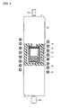
- a SiC substrate 16 in the form of a disk was arranged as a heterogeneous substrate in the top part of a crucible 15 in the crystal growth furnace represented in Fig. 4 , and AlN powder 17 that was a raw material was accommodated in the lower part of the crucible 15.
- the SiC substrate 16 had diameter r of 2 inches (50.8 mm) and thickness of 0.5 mm.
- a seed-crystal protector 18 was arranged so as to closely contact the back side of the SiC substrate 16 to prevent with the seed-crystal protector 18 the SiC substrate 16 from sublimating.
- the crystal growth furnace illustrated in Fig. 4 includes a heat insulator 19 and radiation thermometers 21 a and 21 b.
- the nitrogen gas was continuously flowed into the reaction chamber 22, and volume of the emitted nitrogen gas was controlled so that the gas partial pressure in the reaction chamber 22 was brought to some 10 kPa to 100 kPa. Furthermore, after the AlN crystal heteroepitaxial growth, the AlN crystal was cooled down to room temperature (25°C).
- dislocation density in the AlN crystal when the distance t (mm) from the SiC substrate 16 in the AlN crystal growing direction was 1 mm was 5.0 ⁇ 10 6 (/cm 2 ).
- the AlN crystal heteroepitaxially grown onto the SiC substrate 16 was cut paralleling the surface of the SiC substrate 16 in respective locations at a distance 200 ⁇ m from the SiC substrate 16 and a distance 0.5 mm away from that location, in the direction opposite from that toward where the SiC substrate 16 lay. Then, the surface thereof was polished to a specular finish and etched, to fabricate an AlN crystal substrate (a first AlN crystal substrate A of Embodiment 1) in the form of a disk.
- the first AlN crystal substrate A of Embodiment 1 had diameter of 2 inches (50.8 mm) and thickness of 0.5 mm.
- the full-width at half maximum of an X-ray rocking curve for its (0002) face, and the dislocation density were characterized.
- the results are set forth in Table I.
- the full-width at half maximum of the X-ray rocking curve for its (0002) face was 350 arcsec, and the dislocation density was 5.2 ⁇ 10 6 /cm 2 .
- KOH mass : NaOH mass 1 : 1
- the AlN crystal was cut parallel to the surface of the SiC substrate 16 in each of locations at distances 200 ⁇ m + 2 mm, 200 ⁇ m + 4 mm, 200 ⁇ m + 10 mm, and 200 ⁇ m + 20 mm from the SiC substrate 16, and in locations at a distance of 0.5 mm from each of these locations in the direction opposite from that toward where the SiC substrate 16 lay, to fabricate a first AlN crystal substrate B (cutting point: 200 ⁇ m + 2 mm), a first AlN crystal substrate C (cutting point: 200 ⁇ m + 4 mm), a first AlN crystal substrate D (cutting point: 200 ⁇ m + 10 mm), and a first AlN crystal substrate E (cutting point: 200 ⁇ m + 20 mm) of Embodiment 1.
- the above first AlN crystal substrate A of Embodiment 1 was arranged in the top part of a crucible 15 in a furnace as illustrated in Fig. 4 , and AlN powder 17 that was a raw material was stored in the under part of the crucible 15. Also in this case, a seed-crystal protector 18 was arranged so as to closely contact with the back side of the first AlN crystal substrate A of Embodiment 1 to prevent with the seed-crystal protector 18 the first AlN crystal substrate A of Embodiment 1 from sublimating.
- the nitrogen gas was continuously flowed into the reaction chamber 22, and the volume of the emitted nitrogen gas was controlled so that the gas partial pressure in the reaction chamber 22 was brought to some 10 kPa to 100 kPa. Furthermore, after the AlN crystal homoepitaxial growth, the AlN crystal was cooled down to room temperature (of 25°C).
- the AlN crystal formed in the above manner was cut parallel to the surface of the first AlN crystal substrate A of Embodiment 1 in respective locations at a distance 200 ⁇ m from the first AlN crystal substrate A of Embodiment 1 and at a distance 0.5 mm from that location, in the direction opposite from that toward where the first AlN crystal substrate A of Embodiment 1 lay. Then the surface thereof was polished to a specular finish and etched, to produce an AlN crystal substrate (a second AlN crystal substrate A of Embodiment 1) having diameter of 2 inches and thickness of 0.5 mm in the form of a disk.
- the full-width at half maximum of an X-ray rocking curve for its (0002) face and the dislocation density were evaluated in the same manner as, and under the same conditions as, in the first AlN crystal substrate A of Embodiment 1.
- the results are set forth in Table I.
- the full-width at half maximum of an X-ray rocking curve for its (0002) face was 200 arcsec, and the dislocation density was 2 ⁇ 10 6 /cm 2 .
- AlN crystals were each grown onto the above first AlN crystal substrates B to E of Embodiment 1 to fabricate second AlN crystal substrates B to E of Embodiment 1 respectively from the grown AlN crystals as in the second AlN crystal substrate A of Embodiment 1.
- Table I 1 st AlN crystal substrate cutting position Location 200 ⁇ m away from SiC substrate Location 200 ⁇ m + 2 mm away from SiC substrate Location 200 ⁇ m + 4 mm away from SiC substrate Location 200 ⁇ m + 10 mm away from SiC substrate Location 200 ⁇ m + 20 mm away from SiC substrate FWHM of X-ray rocking curve for 1 st AlN crystal substrate (arcsec) 350 380 100 51 32 Disloc. dens. of 1 st AlN crystal substrate (/cm 2 ) 5.2 ⁇ 10 6 3 ⁇ 10 6 7 ⁇ 10 5 3.4 ⁇ 10 4 9.8 ⁇ 10 3 FWHM of X-ray rocking curve for 2 nd AlN crystal substrate (arcsec) 200 145 80 45 31 Disloc.
- an AlN crystal was heteroepitaxially grown by sublimation onto a SiC substrate to a thickness of, with respect to the SiC substrate diameter r (50.8 mm), 0.4 r (20.32 mm) or more.
- the conditions in Embodiment 1 were modified to carry out the heteroepitaxial growth.
- Dislocation density in the AlN crystal at the AlN crystal thickness t of 1 mm was 6.0 ⁇ 10 6 (/cm 2 ).
- the AlN crystal heteroepitaxially grown onto the SiC substrate was cut parallel to the SiC substrate surface in respective locations at a distance 200 ⁇ m from the SiC substrate and at a distance 0.5 mm from that location, in the direction opposite from that toward where the SiC substrate lay. Then the surface thereof was polished to a specular finish and etched, to fabricate an AlN crystal substrate (a first AlN crystal substrate A of Embodiment 2) in the form of a disk.
- the first AlN crystal substrate A of Embodiment 2 had diameter of 2 inches (50.8 mm) and thickness of 0.5 mm.
- the full-width at half maximum of an X-ray rocking curve for its (0002) face and the dislocation density were evaluated in the same manner as, and under the same conditions as, in Embodiment 1.
- the results are set forth in Table II.
- the full-width at half maximum of an X-ray rocking curve for its (0002) face was 830 arcsec, and the dislocation density was 6 ⁇ 10 6 /cm 2 .
- the AlN crystal was cut parallel to the SiC substrate surface in each of locations at distances 200 ⁇ m + 2 mm, 200 ⁇ m + 4 mm, 200 ⁇ m + 10 mm, and 200 ⁇ m + 20 mm from the SiC substrate, and in locations at a distance of 0.5 mm from each of these locations in the direction opposite from that toward where the SiC substrate lay, to fabricate a first AlN crystal substrate B (cutting point: 200 ⁇ m + 2 mm), a first AlN crystal substrate C (cutting point: 200 ⁇ m + 4 mm), a first AlN crystal substrate D (cutting point: 200 ⁇ m + 10 mm), and a first AlN crystal substrate E(cutting point: 200 ⁇ m + 20 mm) of Embodiment 2.
- an AlN crystal was homoepitaxially grown by sublimation onto the first AlN crystal substrate A of Embodiment 2. And, after the AlN crystal homoepitaxial growth, the AlN crystal was cooled down to room temperature (of 25°C).
- the AlN crystal formed in the above manner was sliced in the same manner as, and under the same conditions as, in Embodiment 1, and the surface thereof was polished to a specular finish and etched, to produce an AlN crystal substrate (a second AlN crystal substrate A of Embodiment 2) having diameter of 2 inches and thickness of 0.5 mm in the form of a disk.
- the full-width at half maximum of an X-ray rocking curve for its (0002) face and the dislocation density were characterized in the same manner as, and under the same conditions as, in Embodiment 1.
- the results are set forth in Table II.
- the full-width at half maximum of an X-ray rocking curve for its (0002) face was 600 arcsec, and the dislocation density was 5.8 ⁇ 10 6 /cm 2 .
- AlN crystals were each grown in the same manner as, and under the same conditions as, in the first AlN crystal substrate A of Embodiment 2, and second AlN crystal substrates B to E of Embodiment 2 were fabricated respectively from the grown AlN crystals, in the same manner as in the second AlN crystal substrate A of Embodiment 2.
- Table II 1 st AlN crystal substrate cutting position Location 200 ⁇ m away from SiC substrate Location 200 ⁇ m + 2 mm away from SiC substrate Location 200 ⁇ m + 4 mm away from SiC substrate Location 200 ⁇ m + 10 mm away from SiC substrate Location 200 ⁇ m + 20 mm away from SiC substrate FWHM of X-ray rocking curve for 1 st AlN crystal substrate (arcsec) 830 900 880 840 800 Disloc. dens.
- the second AlN crystal substrates A to E of Embodiment 2 each exhibited a more favorable full-width at half maximum of an X-ray rocking curve for their (0002) faces and dislocation density, and were further improved in crystallinity, compared with the first AlN crystal substrates A to E of Embodiment 2, that served as a base of each of the second AlN crystal substrates A to E.
- the second AlN crystal substrates A to E of Embodiment 2 each, however, did not have more preferable full-width at half maximum of an X-ray rocking curve for their (0002) faces and dislocation density than the second AlN crystal substrates A to E of Embodiment 1.
- an AlN crystal was heteroepitaxially grown by sublimation to a thickness of, with respect to the SiC substrate diameter r (50.8 mm), 0.4 r (20.32 mm) or more.
- the heteroepitaxial growth was carried out modifying the conditions from Embodiment 1.
- the dislocation density in the AlN crystal at an AlN crystal thickness t of 1 mm was 5.0 ⁇ 10 6 (/cm 2 ).
- the AlN crystal heteroepitaxially grown onto the SiC substrate was cut parallel to the SiC substrate surface in respective locations at a distance 200 ⁇ m from the SiC substrate and at a distance 0.5 mm from that location, in the direction opposite from that toward where the SiC substrate lay. Then, the surface of the crystal cut off was polished to a specular finish, and etched, to fabricate an AlN crystal substrate (a first AlN crystal substrate A of Embodiment 3) in the form of a disk.
- the first AlN crystal substrate A of Embodiment 3 had diameter of 2 inches (50.8 mm) and thickness of 0.5 mm.
- the full-width at half maximum of an X-ray rocking curve for its (0002) face and the dislocation density were evaluated in the same manner as, and under the same conditions as, in Embodiment 1.
- the results are set forth in Table III.
- the full-width at half maximum of an X-ray rocking curve for its (0002) face was 400 arcsec, and the dislocation density was 1.5 ⁇ 10 7 /cm 2 .
- the AlN crystal was cut parallel to the SiC substrate surface in each of locations at distances 200 ⁇ m + 2 mm, 200 ⁇ m + 4 mm, 200 ⁇ m + 10 mm, and 200 ⁇ m + 20 mm from the SiC substrate, and in locations at a distance of 0.5 mm from each of these locations in the direction opposite from that toward where the SiC substrate lay, to fabricate a first AlN crystal substrate B (cutting point: 200 ⁇ m + 2 mm), first AlN crystal substrate C (cutting point: 200 ⁇ m + 4 mm), a first AlN crystal substrate D (cutting point: 200 ⁇ m + 10 mm), and a first AlN crystal substrate E (cutting point: 200 ⁇ m + 20 mm) of Embodiment 3.
- an AlN crystal was homoepitaxially grown by sublimation onto the first AlN crystal substrate A of Embodiment 3. And, after the AlN crystal homoepitaxial growth, the AlN crystal was cooled down to room temperature (of 25°C).
- the AlN crystal formed in the above manner was sliced in the same manner as, and under the same conditions as, in Embodiment 1, and the surface thereof was polished to a specular finish and etched, to produce an AlN crystal substrate (a second AlN crystal substrate A of Embodiment 3) having diameter of 2 inches and thickness of 0.5 mm in the form of a disk.
- the full-width at half maximum of an X-ray rocking curve for its (0002) face and the dislocation density were characterized in the same manner as, and under the same conditions as, in Embodiment 1.
- the results are set forth in Table III.
- the full-width at half maximum of an X-ray rocking curve for its (0002) face was 550 arcsec, and the dislocation density was 6 ⁇ 10 3 /cm 2 .
- AlN crystals were each grown onto the above second AlN crystal substrates B to E of Embodiment 3, and second AlN crystal substrates B to E of Embodiment 3 were fabricated respectively from the grown AlN crystals, in the same manner as in the second AlN crystal substrate A of Embodiment 3.
- Table III 1 st AlN crystal substrate cutting position Location 200 ⁇ m away from SiC substrate Location 200 ⁇ m + 2 mm away from SiC substrate Location 200 ⁇ m + 4 mm away from SiC substrate Location 200 ⁇ m + 10 mm away from SiC substrate Location 200 ⁇ m + 20 mm away from SiC substrate FWHM of X-ray rocking curve for 1 st AlN crystal substrate (arcsec) 400 520 550 650 710 Disloc. dens.
- the second AlN crystal substrates A to E of Embodiment 3 tended to be lower in dislocation density, but were prone to have poor full-width at half maximums of the X-ray rocking curves for their (0002) faces, compared with the second AlN crystal substrates A to E of Embodiment 1.
- the present invention affords AlN crystal substrate manufacturing methods, whereby large-scale, high-quality AlN crystal substrates can be manufactured, AlN crystal growth methods, whereby bulk, superior-crystallinity AlN crystals can be grown, and AlN crystal substrates composed of the AlN crystals grown by the growth methods.
Landscapes
- Chemical & Material Sciences (AREA)
- Engineering & Computer Science (AREA)
- Crystallography & Structural Chemistry (AREA)
- Materials Engineering (AREA)
- Metallurgy (AREA)
- Organic Chemistry (AREA)
- Inorganic Chemistry (AREA)
- Crystals, And After-Treatments Of Crystals (AREA)
- Physical Deposition Of Substances That Are Components Of Semiconductor Devices (AREA)
- Recrystallisation Techniques (AREA)
- Led Devices (AREA)
Applications Claiming Priority (2)
| Application Number | Priority Date | Filing Date | Title |
|---|---|---|---|
| JP2006184453A JP2008013390A (ja) | 2006-07-04 | 2006-07-04 | AlN結晶基板の製造方法、AlN結晶の成長方法およびAlN結晶基板 |
| PCT/JP2007/062076 WO2008004424A1 (fr) | 2006-07-04 | 2007-06-15 | PROCÉDÉ DE FABRICATION D'UN SUBSTRAT DE CRISTAL D'AlN, PROCÉDÉ POUR FAIRE CROÎTRE UN CRISTAL D'AlN ET SUBSTRAT DE CRISTAL D'AlN |
Publications (2)
| Publication Number | Publication Date |
|---|---|
| EP2037012A1 true EP2037012A1 (de) | 2009-03-18 |
| EP2037012A4 EP2037012A4 (de) | 2010-08-11 |
Family
ID=38894395
Family Applications (1)
| Application Number | Title | Priority Date | Filing Date |
|---|---|---|---|
| EP07745331A Withdrawn EP2037012A4 (de) | 2006-07-04 | 2007-06-15 | Verfahren zur herstellung von aln-kristall-substrat, verfahren zum ziehen eines kristalls und aln-kristall-substrat |
Country Status (6)
| Country | Link |
|---|---|
| US (1) | US20090280354A1 (de) |
| EP (1) | EP2037012A4 (de) |
| JP (1) | JP2008013390A (de) |
| KR (1) | KR20090029201A (de) |
| CN (1) | CN101484617B (de) |
| WO (1) | WO2008004424A1 (de) |
Cited By (1)
| Publication number | Priority date | Publication date | Assignee | Title |
|---|---|---|---|---|
| EP2267196A4 (de) * | 2008-04-17 | 2011-06-22 | Sumitomo Electric Industries | Verfahren zum züchten von aln-kristallen und aln-laminat |
Families Citing this family (10)
| Publication number | Priority date | Publication date | Assignee | Title |
|---|---|---|---|---|
| JP2009249200A (ja) * | 2008-04-02 | 2009-10-29 | Fujikura Ltd | 窒化アルミニウム単結晶の製造方法 |
| JP2010068109A (ja) * | 2008-09-09 | 2010-03-25 | Sumitomo Electric Ind Ltd | 弾性表面波素子 |
| JP2010150110A (ja) * | 2008-12-26 | 2010-07-08 | Fujikura Ltd | 窒化物単結晶およびその製造方法 |
| JP5252495B2 (ja) * | 2008-12-26 | 2013-07-31 | 株式会社フジクラ | 窒化アルミニウム単結晶の製造方法 |
| JP5732288B2 (ja) * | 2011-03-18 | 2015-06-10 | 学校法人 名城大学 | 自立基板の製造方法 |
| CN104871431B (zh) * | 2012-12-26 | 2018-04-10 | 日本碍子株式会社 | 复合基板及其制造方法,以及弹性波装置 |
| JP5818853B2 (ja) | 2013-10-15 | 2015-11-18 | 株式会社トクヤマ | n型窒化アルミニウム単結晶基板を用いた縦型窒化物半導体デバイス |
| CN105483833A (zh) * | 2015-11-24 | 2016-04-13 | 北京华进创威电子有限公司 | 一种氮化铝单晶的位错腐蚀方法 |
| CN108085745A (zh) * | 2017-12-28 | 2018-05-29 | 北京华进创威电子有限公司 | 一种氮化铝晶体生长用同质衬底制备及扩径生长方法 |
| WO2021210391A1 (ja) | 2020-04-14 | 2021-10-21 | 学校法人関西学院 | 窒化アルミニウム基板の製造方法、窒化アルミニウム基板、及び、窒化アルミニウム層におけるクラックの発生を抑制する方法 |
Family Cites Families (5)
| Publication number | Priority date | Publication date | Assignee | Title |
|---|---|---|---|---|
| US5858086A (en) * | 1996-10-17 | 1999-01-12 | Hunter; Charles Eric | Growth of bulk single crystals of aluminum nitride |
| US7501023B2 (en) * | 2001-07-06 | 2009-03-10 | Technologies And Devices, International, Inc. | Method and apparatus for fabricating crack-free Group III nitride semiconductor materials |
| JP4622447B2 (ja) * | 2004-01-23 | 2011-02-02 | 住友電気工業株式会社 | Iii族窒化物結晶基板の製造方法 |
| JP2006016294A (ja) * | 2004-05-31 | 2006-01-19 | Sumitomo Electric Ind Ltd | Iii族窒化物結晶の成長方法、iii族窒化物結晶基板および半導体デバイス |
| JP2005343722A (ja) * | 2004-06-01 | 2005-12-15 | Sumitomo Electric Ind Ltd | AlN結晶の成長方法、AlN結晶基板および半導体デバイス |
-
2006
- 2006-07-04 JP JP2006184453A patent/JP2008013390A/ja active Pending
-
2007
- 2007-06-15 CN CN2007800252316A patent/CN101484617B/zh not_active Expired - Fee Related
- 2007-06-15 EP EP07745331A patent/EP2037012A4/de not_active Withdrawn
- 2007-06-15 US US12/306,695 patent/US20090280354A1/en not_active Abandoned
- 2007-06-15 KR KR1020087030004A patent/KR20090029201A/ko not_active Withdrawn
- 2007-06-15 WO PCT/JP2007/062076 patent/WO2008004424A1/ja not_active Ceased
Cited By (1)
| Publication number | Priority date | Publication date | Assignee | Title |
|---|---|---|---|---|
| EP2267196A4 (de) * | 2008-04-17 | 2011-06-22 | Sumitomo Electric Industries | Verfahren zum züchten von aln-kristallen und aln-laminat |
Also Published As
| Publication number | Publication date |
|---|---|
| KR20090029201A (ko) | 2009-03-20 |
| CN101484617B (zh) | 2013-07-10 |
| JP2008013390A (ja) | 2008-01-24 |
| EP2037012A4 (de) | 2010-08-11 |
| US20090280354A1 (en) | 2009-11-12 |
| WO2008004424A1 (fr) | 2008-01-10 |
| CN101484617A (zh) | 2009-07-15 |
Similar Documents
| Publication | Publication Date | Title |
|---|---|---|
| US20090280354A1 (en) | Process for Producing Substrate of AlN Crystal, Method of Growing AlN Crystal, and Substrate of AlN Crystal | |
| TWI750628B (zh) | 碳化矽晶圓以及碳化矽晶圓之製備方法 | |
| JPWO2016088883A1 (ja) | 炭化珪素単結晶の製造方法及び炭化珪素単結晶基板 | |
| TWI750630B (zh) | 碳化矽錠之製備方法、碳化矽晶圓之製備方法以及其系統 | |
| WO2008089181A2 (en) | Guided diameter sic sublimation growth with multi-layer growth guide | |
| CN101370972B (zh) | 用于制造氮化铝晶体的方法、氮化铝晶体、氮化铝晶体衬底和半导体器件 | |
| US20110110840A1 (en) | Method for producing group iii-nitride crystal and group iii-nitride crystal | |
| US12080551B2 (en) | SiC composite substrate including biaxially oreinted SiC layer and semiconductor device | |
| EP4428273A1 (de) | Verfahren zur herstellung eines sic-wafers und verfahren zur herstellung eines sic-ingots | |
| US20190194822A1 (en) | SiC INGOT AND METHOD OF MANUFACTURING SiC INGOT | |
| US20230392290A1 (en) | AlN SINGLE CRYSTAL SUBSTRATE | |
| CN114108077A (zh) | 碳化硅锭的制造方法及由此制成的碳化硅锭 | |
| JP2006225232A (ja) | 炭化珪素単結晶の製造方法、炭化珪素単結晶インゴット、炭化珪素単結晶基板、炭化珪素エピタキシャルウェハ、および薄膜エピタキシャルウェハ | |
| KR102605845B1 (ko) | Ⅲ족 질화물 반도체 기판 및 ⅲ족 질화물 반도체 기판의 제조방법 | |
| JP5162895B2 (ja) | 窒化アルミニウム結晶の製造方法、窒化アルミニウム結晶、窒化アルミニウム結晶基板および半導体デバイス | |
| JP2006016294A (ja) | Iii族窒化物結晶の成長方法、iii族窒化物結晶基板および半導体デバイス | |
| US12037704B2 (en) | Silicon carbide wafer and method of manufacturing same | |
| JP2008230868A (ja) | 窒化ガリウム結晶の成長方法および窒化ガリウム結晶基板 | |
| US20260009159A1 (en) | AlN SINGLE CRYSTAL SUBSTRATE AND DEVICE | |
| JP2013006740A (ja) | 結晶の製造方法および結晶 | |
| JP2010265131A (ja) | 窒化物単結晶の製造方法 | |
| JP2011121835A (ja) | 結晶の製造方法および結晶 | |
| HK1137491A (en) | Method of manufacturing iii nitride crystal, iii nitride crystal substrate, and semiconductor device |
Legal Events
| Date | Code | Title | Description |
|---|---|---|---|
| PUAI | Public reference made under article 153(3) epc to a published international application that has entered the european phase |
Free format text: ORIGINAL CODE: 0009012 |
|
| 17P | Request for examination filed |
Effective date: 20081217 |
|
| AK | Designated contracting states |
Kind code of ref document: A1 Designated state(s): AT BE BG CH CY CZ DE DK EE ES FI FR GB GR HU IE IS IT LI LT LU LV MC MT NL PL PT RO SE SI SK TR |
|
| AX | Request for extension of the european patent |
Extension state: AL BA HR MK RS |
|
| RBV | Designated contracting states (corrected) |
Designated state(s): DE FR GB |
|
| A4 | Supplementary search report drawn up and despatched |
Effective date: 20100708 |
|
| 17Q | First examination report despatched |
Effective date: 20110512 |
|
| DAX | Request for extension of the european patent (deleted) | ||
| STAA | Information on the status of an ep patent application or granted ep patent |
Free format text: STATUS: THE APPLICATION IS DEEMED TO BE WITHDRAWN |
|
| 18D | Application deemed to be withdrawn |
Effective date: 20160105 |