EP2037016A1 - Carde avec habillage - Google Patents
Carde avec habillage Download PDFInfo
- Publication number
- EP2037016A1 EP2037016A1 EP07017785A EP07017785A EP2037016A1 EP 2037016 A1 EP2037016 A1 EP 2037016A1 EP 07017785 A EP07017785 A EP 07017785A EP 07017785 A EP07017785 A EP 07017785A EP 2037016 A1 EP2037016 A1 EP 2037016A1
- Authority
- EP
- European Patent Office
- Prior art keywords
- portal
- machine
- spool
- flaps
- carding
- Prior art date
- Legal status (The legal status is an assumption and is not a legal conclusion. Google has not performed a legal analysis and makes no representation as to the accuracy of the status listed.)
- Withdrawn
Links
- 238000009960 carding Methods 0.000 title claims description 23
- 239000000835 fiber Substances 0.000 description 5
- 238000010276 construction Methods 0.000 description 3
- 239000011521 glass Substances 0.000 description 3
- 238000012423 maintenance Methods 0.000 description 3
- 238000012546 transfer Methods 0.000 description 3
- 235000014676 Phragmites communis Nutrition 0.000 description 2
- 241001417494 Sciaenidae Species 0.000 description 2
- ZYXYTGQFPZEUFX-UHFFFAOYSA-N benzpyrimoxan Chemical compound O1C(OCCC1)C=1C(=NC=NC=1)OCC1=CC=C(C=C1)C(F)(F)F ZYXYTGQFPZEUFX-UHFFFAOYSA-N 0.000 description 2
- 229920003229 poly(methyl methacrylate) Polymers 0.000 description 2
- 239000004926 polymethyl methacrylate Substances 0.000 description 2
- 238000009966 trimming Methods 0.000 description 2
- 238000013459 approach Methods 0.000 description 1
- 230000001143 conditioned effect Effects 0.000 description 1
- 230000003750 conditioning effect Effects 0.000 description 1
- 230000001419 dependent effect Effects 0.000 description 1
- 238000013461 design Methods 0.000 description 1
- 238000011161 development Methods 0.000 description 1
- 238000006073 displacement reaction Methods 0.000 description 1
- 230000007613 environmental effect Effects 0.000 description 1
- 238000000926 separation method Methods 0.000 description 1
Images
Classifications
-
- D—TEXTILES; PAPER
- D01—NATURAL OR MAN-MADE THREADS OR FIBRES; SPINNING
- D01G—PRELIMINARY TREATMENT OF FIBRES, e.g. FOR SPINNING
- D01G15/00—Carding machines or accessories; Card clothing; Burr-crushing or removing arrangements associated with carding or other preliminary-treatment machines
- D01G15/02—Carding machines
- D01G15/12—Details
- D01G15/32—Framework; Casings; Coverings
Definitions
- the present invention relates to a card with a cover flap having housing according to the preamble of claim 1.
- a card of this kind is in a collective leaflet of SPINNBAU GmbH, Bremen, 1999, pages 32 and 33 shown.
- a card which has a hood-shaped housing which is displaceable in total or in telescopically movable, rigid sections transverse to the roller axes of the card to expose the machine frame holding the rollers as a whole, so that the uppermost worker and Wenderwalzencrue for a crane freely accessible become.
- this card when the card sections are moved apart, the entire housing must be moved along, and it requires an additional space next to the card, in order to be able to move the housing sufficiently far, if the entire card has been uncovered in the disassembled state of its sections.
- the invention has for its object to provide a card of the aforementioned type, which facilitates access to all worker and Wenderwalzencruen from above with minimal space requirement laterally next to the card.
- the invention solves the portals of the machine frame, so that by moving the machine frame and portals against each other, the / the spool (e) each roller can be made freely accessible from above. Because the elements essentially forming the housing, namely the flaps and doors, are largely flat, a portal with the flaps and doors hinged thereto is a substantially flat, ie disc-shaped structure, which has little space transversely to the axial direction of the rollers What makes the accessibility to the rollers already from home and makes each roller freely accessible from above by mutual adjustment of machine frame and portal. Because of this disk-shaped shape of an "open portal" and the more space required when moving apart of the sections of a multi-section carding over a construction with movable rigid hoods is very reduced.
- the accessibility to some of the rolls can be further improved if the portals are pivotally mounted so that they can be tilted in whole or in part.
- the rollers mounted further down next to a drum are more easily accessible without having to move a portal or the relevant machine section.
- the stand of the portal are telescopically extendable, which further improves the accessibility of the rollers. This applies in particular to a portal located in the carding area, where a telescopic startup of the portal makes it possible to drive through the higher-level carding sections under the portal.
- the present in carding boxes usually glazed doors that allow access to the working space of the carding from the side are mounted in the invention carding on the uprights of the portals and are preferably folding doors to reduce the footprint in the open state of the doors.
- FIGS. 1 to 5 show different embodiments of the flaps holding portals in different positions of the same. These can be different variants of a housing construction, these variants can also be combined with each other, ie the FIGS. 1 to 5 can also stand for five different states of the portals and the valves held by them of a single housing construction, as will be explained later.
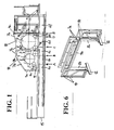
- Fig. 1 shows a card with a pre-bambour 1 and a main reel 2, a arranged between these two Tambouren transfer roller group 3 and two on the main reel 2 superposed pickup rollers 4.
- the two Tambouren 1 and 2 are each assigned a plurality of worker / Wenderwalzencrue 5, the above the upper Half of the drum circumference are arranged distributed.
- the reels 1 and 2, the transfer rollers 3 and the pickup rollers 4 are mounted in a machine frame, which is divided in the example shown in five sections 6a to 6e, of which the Tamboure 1 and 2 and the transfer rollers 3 overlapping sections in the example shown in FIG a machine substructure 15 transversely to the axial direction of the Tamboure be moved horizontally. This will be discussed later.
- the card has a housing that surrounds the card against fiber fly and Protects noise and the working space of the card against environmental influences and allows to condition the working space of the card, for example, set certain humidities by supplying appropriately treated air. From this case are in Fig. 1 only the reels 1 and 2 and their worker / Wenderwalzenpase 5 on its upper side covering flaps 7a, 7b shown in the closed state and the flaps 7a and 7b holding support structures. For reasons of clarity, the housing laterally completing walls, which are usually formed by movable, mostly glazed doors, not shown. This can, however, on Fig. 6 to get expelled.
- the flaps 7a and 7b are each held on a portal, which consists of uprights 8a, 8b and 8c and connecting two stands each cross member 9a, 9b and 9c, see also Fig. 6 .
- the portal 8c, 9c is on the in Fig. 1 is located to the right of the discharge side of the main drum 2 and carries a pivoting flap 7b, part of a section 6f of the machine frame, which may be immobile depending on the machine design, or not.
- a second, arranged in the area between the axes of the Vortambour 1 and main reed 2 portal 8b, 9b is located approximately at the level of the delivery side of the pretortoon 1.
- This portal 8b, 9b carries at its upper end two pivoting flaps 7a facing away from each other.
- a third portal 8a, 9a is arranged on the inlet side of the foremost orchestra 1 and carries at its upper end a single flap 7b.
- the flaps 7a and 7b are dimensioned such that in the closed state they close the space above the two reels 1 and 2. This condition is in Fig. 1 shown.
- louvers which are partially fixed in place in the machine frame and in the example shown are partially attached to the flaps 7b.
- the fixedly held louvers are essentially sidewalls which, in the closed state of the flaps 7b, cooperate with the louvers mounted on the flaps to enclose the narrower airspace around the reels 1 and 2 with their worker / inverter roller pairs 5.
- the flaps 7a and 7b preferably have glass fillings or Acrylglas
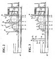
- Fig. 2 shows the arrangement of Fig. 1 in the opened state of the flaps 7a and 7b. It can be seen that the worker / reversing roller pairs 5 arranged in the apex of the reels 1 and 2 and also the roller pairs 5 adjacent to them are now freely accessible from above. They can therefore be easily lifted out of the machine frame by means of a crane.
- Fig. 2 at least the portal 8b, 9b, which is arranged between the two Tambouren 1 and 2, divided in the region of the foot of its stand 8b by means of a hinge 11, so that the upper segments of the stand 8b can be swung to the side.
- Fig. 2 shows namely the possibility that opens the pivotal storage of a portal. It shows a sideways inclined state of the arranged between the two Tambouren 1 and 2 portals 8b, 9b. It is pivoted from the vertical so far that the area between the two Tambouren 1 and 2 is completely freely accessible from above. As indicated in the drawing by the corresponding hinge 11 at the foot of the stand 8a of the laterally arranged to the pre-bambour 1 portal 8a, 9a, this portal 8a, 9a can be pivoted to make the inlet area of the foremost 1 more accessible from above.
- Fig. 3 shows an alternative solution for making the reels accessible from above.
- the two portals 8a, 9a and 8b, 9b, in the inlet region of the foremost orchestra 1 and between the first bassoon 1 and main tambour 2 are arranged on rails 12 transversely to the axial direction of the reels 1 and 2 in the machine base 15 movable.
- Fig. 3 shows the state in which the aforementioned portals are moved to the left, so that the reels 1 and 2 and all worker / Wenderwalzencrue 5 are freely accessible from above.
- the exemplary carding machine is subdivided into several sections which are movable relative to one another on rails 13 transversely to the axial direction of the rollers.
- Fig. 1 are the separation points at which the machine frame is divided into sections 6a to 6f, highlighted by the reference numerals A, B, C, D and E.
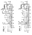
- Fig. 4 shows a state in the sections 6a to 6e of the machine frame on the rails 13 to the left, thereby forming mutual distances from the in Fig. 1 shown shifted position, so that in each case a gap between the sections 6a to 6f results.
- the portal 8a, 9a has been moved with the first section 6a on its own rails 12, while the portal 8b, 9b has remained in its original position.
- rollers are freely accessible from above.
- the upper worker / Wenderwalzen pairs 5 of the main drum 2 are also freely accessible from above with a suitable position of the main drum 2.
- it can be provided to also form the movable in operation between Vortambour 1 and main tambour 2 portal movable and to push during maintenance on the rails 12 to the side, which in Fig. 5 is shown.
- tubular channels 10 are shown as louvers, which are coupled in the closed state of the flaps 7b with fixedly mounted on the machine base or so firmly connected to the components sections of the louvers.
- These channels 10 have openings which are directed against the rollers opposite them.
- the openings may consist of a long slot or a plurality of distributed holes through which fibers can be sucked or air directed against the rollers.
- Fig. 6 shows a perspective view of the standing in operation between Vortambour 1 and main drum 2 portal, consisting of the uprights 8b and the cross member 9b. It is shown displaceably in rails 12. On the representation of joints for lateral pivoting of this portal (see Fig. 2 ) was omitted here.
- the flaps 7a are pivotally mounted, shown here consisting of frame, which are filled by glass or acrylic glass plates to view the working space of the carding also from above.
- the uprights folding doors 14 are further attached laterally, which in Fig. 6 are shown in the open state and also consist of frames with glass or acrylic glass fillings.
- the cross member may optionally carry an air duct or form itself.
Landscapes
- Engineering & Computer Science (AREA)
- Textile Engineering (AREA)
- Preliminary Treatment Of Fibers (AREA)
Priority Applications (1)
| Application Number | Priority Date | Filing Date | Title |
|---|---|---|---|
| EP07017785A EP2037016A1 (fr) | 2007-09-11 | 2007-09-11 | Carde avec habillage |
Applications Claiming Priority (1)
| Application Number | Priority Date | Filing Date | Title |
|---|---|---|---|
| EP07017785A EP2037016A1 (fr) | 2007-09-11 | 2007-09-11 | Carde avec habillage |
Publications (1)
| Publication Number | Publication Date |
|---|---|
| EP2037016A1 true EP2037016A1 (fr) | 2009-03-18 |
Family
ID=39269028
Family Applications (1)
| Application Number | Title | Priority Date | Filing Date |
|---|---|---|---|
| EP07017785A Withdrawn EP2037016A1 (fr) | 2007-09-11 | 2007-09-11 | Carde avec habillage |
Country Status (1)
| Country | Link |
|---|---|
| EP (1) | EP2037016A1 (fr) |
Cited By (1)
| Publication number | Priority date | Publication date | Assignee | Title |
|---|---|---|---|---|
| WO2022122226A1 (fr) * | 2020-12-09 | 2022-06-16 | TRüTZSCHLER GMBH & CO. KG | Carde pour la fabrication d'un non-tissé à partir d'un matériau fibreux |
Citations (5)
| Publication number | Priority date | Publication date | Assignee | Title |
|---|---|---|---|---|
| GB869308A (en) * | 1958-08-06 | 1961-05-31 | Tweedales & Smalley Ltd | Improved casing closures for textile machinery |
| DE1139413B (de) | 1959-09-03 | 1962-11-08 | Carl Otto Muellenschlaeder | Walzenkrempel |
| WO1993002237A1 (fr) * | 1991-07-23 | 1993-02-04 | Carding Specialists (Canada) Limited | Dispositif de securite pour machine a carder |
| DE10242929A1 (de) * | 2002-09-16 | 2004-03-18 | Trützschler GmbH & Co KG | Vorrichtung an einer Spinnereivorbereitungsmaschine, insbesondere Karde, mit einer Maschinenverkleidung |
| DE602005000750T2 (de) * | 2005-01-26 | 2007-11-22 | Asselin-Thibeau | Karde mit verschiebbaren Ummantelung |
-
2007
- 2007-09-11 EP EP07017785A patent/EP2037016A1/fr not_active Withdrawn
Patent Citations (5)
| Publication number | Priority date | Publication date | Assignee | Title |
|---|---|---|---|---|
| GB869308A (en) * | 1958-08-06 | 1961-05-31 | Tweedales & Smalley Ltd | Improved casing closures for textile machinery |
| DE1139413B (de) | 1959-09-03 | 1962-11-08 | Carl Otto Muellenschlaeder | Walzenkrempel |
| WO1993002237A1 (fr) * | 1991-07-23 | 1993-02-04 | Carding Specialists (Canada) Limited | Dispositif de securite pour machine a carder |
| DE10242929A1 (de) * | 2002-09-16 | 2004-03-18 | Trützschler GmbH & Co KG | Vorrichtung an einer Spinnereivorbereitungsmaschine, insbesondere Karde, mit einer Maschinenverkleidung |
| DE602005000750T2 (de) * | 2005-01-26 | 2007-11-22 | Asselin-Thibeau | Karde mit verschiebbaren Ummantelung |
Cited By (1)
| Publication number | Priority date | Publication date | Assignee | Title |
|---|---|---|---|---|
| WO2022122226A1 (fr) * | 2020-12-09 | 2022-06-16 | TRüTZSCHLER GMBH & CO. KG | Carde pour la fabrication d'un non-tissé à partir d'un matériau fibreux |
Similar Documents
| Publication | Publication Date | Title |
|---|---|---|
| EP2017081B1 (fr) | Dispositif de manipulation d'une presse d' impression | |
| DE102008003816A1 (de) | Röntgeneinrichtung umfassend einen vorzugsweise an einem Roboterarm drehgelagerten C-Bogen | |
| DE102008003815A1 (de) | Röntgeneinrichtung umfassend einen vorzugsweise an einem Roboterarm um eine Drehachse drehbar gelagerten C-Bogen | |
| DE112017005965T5 (de) | Untersuchungssystem | |
| EP0008082B1 (fr) | Garage pour garer les véhicules l'un au-dessus de l'autre | |
| EP0865869A1 (fr) | Cellule d'automatisation pour manipuler des pieces | |
| EP1538270A1 (fr) | Conteneur | |
| EP0815382B1 (fr) | Insonorisation | |
| EP2774634A1 (fr) | Machine de dialyse avec boîtier de machine autoporteur | |
| DE602005000750T2 (de) | Karde mit verschiebbaren Ummantelung | |
| DE3936340A1 (de) | Vorrichtung zum bewegen einer ladebordwand | |
| DE10113664A1 (de) | Vorrichtmaschine zum Richten insbesondere der Bandanfänge und -enden von gewalzten Bändern bzw. Blechen | |
| EP2631019A1 (fr) | Dresseuse | |
| DE10025316A1 (de) | Antriebseinheit | |
| DE102020132835A1 (de) | Krempel für die Herstellung von Vlies aus Fasermaterial | |
| EP0847950B1 (fr) | Capot insonorisant pour une plieuse à poches | |
| DE69120451T2 (de) | Umfüllvorrichtung für Material in Turmmälzereien | |
| DE2435972A1 (de) | Rollenrotationsdruckmaschine in stockwerkbauweise | |
| DE1954675A1 (de) | Abrollvorrichtung fuer Wickel aus Bandeisen,Draehten od.dgl. | |
| EP2683637B1 (fr) | Dispositif de guidage sans contact et de séchage d'une bande de matériau | |
| DE102015211300A1 (de) | Einrichtung und Verfahren zum Einbringen einer Bespannung in eine Bahnbildungsmaschine | |
| DE1685529A1 (de) | Krempelmaschine,insbesondere Deckelkrempel | |
| DE102016109542A1 (de) | Streckanlage für textile Faserbänder | |
| EP3257981B1 (fr) | Installation d'étirage pour bandes de fibres textiles | |
| DE202016101095U1 (de) | Melkstand mit einer Antriebsanordnung für Melkstandtore |
Legal Events
| Date | Code | Title | Description |
|---|---|---|---|
| PUAI | Public reference made under article 153(3) epc to a published international application that has entered the european phase |
Free format text: ORIGINAL CODE: 0009012 |
|
| AK | Designated contracting states |
Kind code of ref document: A1 Designated state(s): AT BE BG CH CY CZ DE DK EE ES FI FR GB GR HU IE IS IT LI LT LU LV MC MT NL PL PT RO SE SI SK TR |
|
| AX | Request for extension of the european patent |
Extension state: AL BA HR MK RS |
|
| 17P | Request for examination filed |
Effective date: 20090908 |
|
| 17Q | First examination report despatched |
Effective date: 20091002 |
|
| AKX | Designation fees paid |
Designated state(s): AT DE FR IT |
|
| STAA | Information on the status of an ep patent application or granted ep patent |
Free format text: STATUS: THE APPLICATION HAS BEEN WITHDRAWN |
|
| 18W | Application withdrawn |
Effective date: 20110125 |