EP2037044A1 - Straßenmarkierungssystem zur Zusammenführung von Fahrspuren - Google Patents
Straßenmarkierungssystem zur Zusammenführung von Fahrspuren Download PDFInfo
- Publication number
- EP2037044A1 EP2037044A1 EP08290858A EP08290858A EP2037044A1 EP 2037044 A1 EP2037044 A1 EP 2037044A1 EP 08290858 A EP08290858 A EP 08290858A EP 08290858 A EP08290858 A EP 08290858A EP 2037044 A1 EP2037044 A1 EP 2037044A1
- Authority
- EP
- European Patent Office
- Prior art keywords
- arms
- signaling devices
- traffic
- road
- circulation
- Prior art date
- Legal status (The legal status is an assumption and is not a legal conclusion. Google has not performed a legal analysis and makes no representation as to the accuracy of the status listed.)
- Granted
Links
- 230000011664 signaling Effects 0.000 claims abstract description 41
- 239000012530 fluid Substances 0.000 claims abstract description 14
- 238000004804 winding Methods 0.000 claims description 7
- 238000002347 injection Methods 0.000 claims description 4
- 239000007924 injection Substances 0.000 claims description 4
- 238000007599 discharging Methods 0.000 claims 1
- 239000008186 active pharmaceutical agent Substances 0.000 abstract description 12
- XLYOFNOQVPJJNP-UHFFFAOYSA-N water Substances O XLYOFNOQVPJJNP-UHFFFAOYSA-N 0.000 abstract description 5
- 230000004888 barrier function Effects 0.000 description 7
- 238000006386 neutralization reaction Methods 0.000 description 3
- 238000011144 upstream manufacturing Methods 0.000 description 3
- 239000003795 chemical substances by application Substances 0.000 description 2
- 230000000694 effects Effects 0.000 description 2
- 238000000034 method Methods 0.000 description 2
- 239000000243 solution Substances 0.000 description 2
- 241000219504 Caryophyllales Species 0.000 description 1
- 241000287107 Passer Species 0.000 description 1
- 230000002528 anti-freeze Effects 0.000 description 1
- 239000002131 composite material Substances 0.000 description 1
- 239000004744 fabric Substances 0.000 description 1
- 239000007788 liquid Substances 0.000 description 1
- 239000000463 material Substances 0.000 description 1
- 239000002184 metal Substances 0.000 description 1
- 238000000926 separation method Methods 0.000 description 1
- 230000035939 shock Effects 0.000 description 1
- 229920002994 synthetic fiber Polymers 0.000 description 1
Images

Classifications
-
- E—FIXED CONSTRUCTIONS
- E01—CONSTRUCTION OF ROADS, RAILWAYS, OR BRIDGES
- E01F—ADDITIONAL WORK, SUCH AS EQUIPPING ROADS OR THE CONSTRUCTION OF PLATFORMS, HELICOPTER LANDING STAGES, SIGNS, SNOW FENCES, OR THE LIKE
- E01F13/00—Arrangements for obstructing or restricting traffic, e.g. gates, barricades ; Preventing passage of vehicles of selected category or dimensions
- E01F13/04—Arrangements for obstructing or restricting traffic, e.g. gates, barricades ; Preventing passage of vehicles of selected category or dimensions movable to allow or prevent passage
-
- E—FIXED CONSTRUCTIONS
- E01—CONSTRUCTION OF ROADS, RAILWAYS, OR BRIDGES
- E01F—ADDITIONAL WORK, SUCH AS EQUIPPING ROADS OR THE CONSTRUCTION OF PLATFORMS, HELICOPTER LANDING STAGES, SIGNS, SNOW FENCES, OR THE LIKE
- E01F13/00—Arrangements for obstructing or restricting traffic, e.g. gates, barricades ; Preventing passage of vehicles of selected category or dimensions
- E01F13/04—Arrangements for obstructing or restricting traffic, e.g. gates, barricades ; Preventing passage of vehicles of selected category or dimensions movable to allow or prevent passage
- E01F13/06—Arrangements for obstructing or restricting traffic, e.g. gates, barricades ; Preventing passage of vehicles of selected category or dimensions movable to allow or prevent passage by swinging into open position about a vertical or horizontal axis parallel to the road direction, i.e. swinging gates
Definitions
- the invention relates to a road marking system for producing a "folding bevel".
- a folding or deflection bevel is a marking system that can gradually neutralize one or more lanes of a road or highway, and constrain vehicles to fall back on the adjacent traffic lanes.
- folding bevels can be made using signs and traffic cones reported on site and simply arranged on the roadway.
- this solution entails a significant danger for the agents in charge of the implementation of the folding bevel, and this especially when the neutralization of the fast lane of a motorway is required. Indeed, in this case, a service vehicle carrying the signs and cones parked on the side and agents must cross several times the road carrying said panels and cones.
- the document FR2886656 discloses a road marking system for producing a folding bevel constituted by a plurality of aligned signaling devices spaced from each other along an edge of a roadway.
- Each device comprises a rigid arm which can be pivoted - manually or with the aid of a motor - from a first position, in which it does not impede the circulation, to a second position, in which it extends through the road, and vice versa.
- the arms have increasing lengths in the direction of vehicle traffic, so as to form a folding bevel.
- Such a system makes the neutralization of a taxiway a much faster and less dangerous operation than by resorting to the traditional method described above.
- the document system FR2886656 difficult to neutralize two or more traffic lanes simultaneously, since the arms of the signaling devices excessive length. For example, when you want to close a section of highway and force all vehicles to use an exit lane, it is necessary to make a folding bevel extending through two or three, or even four, traffic lanes, that is to say on a width of road that can exceed 14 meters. In practice, a folding wedge of these dimensions can now be achieved only by the traditional method.
- the present invention provides an improved marking system, not having the disadvantages that make the document system FR2886656 poorly adapted to the neutralization of a plurality of traffic lanes.
- signaling devices comprising inflatable arms constituted by flexible tubular structures, which can pass from a folded state to an unfolded or extended state by injection of a fluid under pressure, and return to the folded state by evacuation of said fluid.
- These arms can have relatively long lengths, up to 14 meters or more, while remaining easy to handle, because they occupy very little space in the folded state, their unfolding is by simple inflation and no pivoting operation unfolded or extended arms are not required.
- Pneumatic signaling devices using inflatable arms are known from the document WO 03/027398 , which discloses the use only as access barriers, for example for car parks.
- An object of the invention is therefore a road marking system constituted by a plurality of aligned signaling devices spaced apart from one another along an edge of a roadway comprising at least one traffic lane, each device comprising an arm able to move from a first position, in which it does not interfere with traffic, to a second position, in which it extends through at least one said taxiway to prevent the passage of any vehicle, and vice versa , the arms of the various signaling devices presenting increasing lengths in a direction of vehicle traffic so as to constitute a folding bevel, said system being characterized in that said arms are constituted by flexible tubular structures which can pass from said first to said second position by inflation by means of a fluid.
- Another object of the invention is a road marking system constituted by a plurality of aligned signaling devices spaced from each other along an edge of a roadway comprising at least one traffic lane, each device comprising an arm able to move from a first position, in which it does not interfere with traffic, to a second position, in which it extends through at least one said taxiway to prevent the passage of any vehicle, and vice versa , the arms of the various signaling devices having increasing lengths in a direction of vehicle traffic so as to constitute a folding bevel, said system being characterized in that it comprises: a first elementary system, constituted by signaling whose arms are rigid elements that can be moved between the first and the second position, and a second system Elemental me, inflatable arm type described above, disposed downstream of said first elementary system in said direction of vehicle traffic.
- Such a “hybrid” system can be applied in particular to a road surface comprising a plurality of traffic lanes intended to be traversed in the same direction of circulation, the first elementary system being constituted by signaling devices whose arms have lengths allowing closure to the circulation of only one of said channels, and the second elementary system being constituted by signaling devices whose arms have lengths allowing closure to the circulation of at least one of said other channels.
- a system according to the invention may be applied in particular to a road pavement comprising a plurality of traffic lanes intended to be traversed in the same direction of circulation and an exit lane situated on the side of the road. the road opposite the one along which the signaling devices are arranged, the length of the arms of said signaling devices being sufficient to close all the traffic lanes and to force the vehicles traveling along the road to use said exit lane.
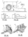
- FIG 1 represents, in a very schematic manner, a DS signaling device that can be used in a road marking system according to the invention.
- a DS signaling device that can be used in a road marking system according to the invention.
- such a device may be disposed adjacent to a separation barrier, or guardrail, GBA, the side of the latter opposite the CH pavement.
- GBA separation barrier
- an opening or reservation must be made in the GBA barrier to allow the passage of the inflatable arm, during inflation of the latter.
- the inflatable arm 20 may pass over the GBA barrier, or below a metal guardrail.
- the signaling device DS comprises a storage box 1, intended to contain the tubular structure 20 constituting the arm in its folded state.
- a winding means 10 in the form of a drum or drum is provided inside the box 1 for spirally winding the tubular structure 20 in its deflated state.
- the drum 10 can be rotated by a motor (not shown) so as to wind and unwind the structure 20.
- a torsion spring in this case, during inflation, the tubular structure 20 takes place under the effect of the fluid pressure and against the return force of the spring, the latter causing its winding during deflation.
- the folding of the deflated arm can be done manually.
- the signaling device 1 also comprises means for inflating and deflating the flexible tubular structure 20.
- these inflating and deflating means comprise a compressor 11 and a pipe 12 connecting said compressor to a proximal end of the structure 20, attached to the winding drum 10.
- a valve may be provided at the distal end of the flexible tubular structure to discharge the fluid that would remain trapped in said structure during its winding.
- the generic term "fluid" has been used, it is understood that the inflatable arms will most often be inflated with a gas, and more particularly with air.
- the use of a liquid, in particular water may nevertheless be of interest. Water-filled barriers have greater ability to stop vehicles, even trucks, while effectively cushioning shocks.
- an inflatable arm must have sufficient dimensions to be clearly seen by the drivers and to constitute a real obstacle to the passage of vehicles.
- the diameter (defined broadly as the largest transverse dimension) of such an arm can be understood typically between 40 cm and 1.50 m, and preferably between 50 cm and 1 m.
- the cross section of a tubular structure adapted to the implementation of the invention may have different shapes, for example it may be circular, trapezoidal or more generally polygonal.
- the cross section of the arm 20 need not necessarily remain constant over the entire length of the latter.
- FIGS 3A and 3B show two variants of an embodiment of the invention in which the inflatable arm 20 ', 20 "is constituted by a plurality of elementary flexible tubular elements 21 interconnected by a flexible connecting structure 22', 22",
- This embodiment is advantageous because it allows the arm to be inflated much more rapidly, and it is also more flexible and therefore less dangerous for road users in the event of a collision.
- This type can have a wide variety of shapes, which increase the visibility of drivers on vehicles traveling on the road.
- the arm 20 'of the figure 3A consists of three elementary tubular arms 21 which can be qualified as "double flanges" arranged in equilateral triangle. These elementary arms are interconnected by a flexible fabric connecting structure 22 'having a star shape with three points with a tubular core, as well as tie rods 22 ".
- the arm 20 "of the figure 3B presents an even more complex structure. It is also constituted by a set of three elementary tubular arms 21, but they have a pace in waves or crenellations, moving away and getting closer to each other periodically.
- connection 3 ' in the form of a star with three points in the sections of the arm 20' where the elements 21 are spaced apart, and by a common external envelope 22 "', in the sections where these elemental arms are closer together.
- the length of an inflatable arm 20, 20 'in its fully extended state may advantageously be of the order of 12 or 15 m, to be able to extend through three or four traffic lanes with a width of 3.5m. In use, however, only the most downstream arm, relative to the direction of the traffic, will be extended to its maximum length.
- an inflatable arm of the required dimensions can hardly be kept straight under the sole effect of its inflation pressure (it is even excluded, in the case of inflation with water). That's why Figures 1 and 2B show arms 20 bearing on the CH roadway.
- the flexible tubular structure 20 must be made of a material (typically a synthetic fabric) capable of withstanding the friction that occur during its inflation and deflation.
- the elementary arms 21 of a "composite" barrier of the type represented on the Figures 3A and 3B can be freestanding, less when inflated in the air.
- each arm 20, 20 ', 20 preferably has patterns such as arrows to indicate to the drivers of the approaching vehicles that they must fall back on another lane of traffic.
- 20 ', 20 Figures 3A and 3B have alternating sections of white and red color.
- the arms may comprise reflective elements and / or lighting means (lamps, light-emitting diodes) to be visible at night.
- lighting means lamps, light-emitting diodes
- the figure 4 shows the use of a system S of the invention to close to circulation a highway section comprising three traffic lanes, V1, V2 and V3, and an exit track or ramp VS, each lane having a width of 3.5 m.
- the traffic is on the right; the direction of travel of the vehicles is therefore from the bottom of the sheet upwards.
- the latter can be automated, by providing upstream of the system S variable message panels and / or light emitting diode signs that can be operated if necessary.
- the system S is constituted by a set of signaling devices DS, DS ', arranged along the left edge of the roadway and separated from the traffic lanes by a GBA barrier.
- the system is not represented to scale, and in fact the signaling devices must be much more distant from each other than it appears from the figure.
- Each signaling device comprises an arm which, in use, extends perpendicularly to the direction of circulation.
- the length of the arms increases in the direction of vehicle traffic: thus the most upstream arm (at the lower end of the figure) can have a length of the order of 1 m, while the most downstream arm measures approximately 12m to block the three lanes.
- any vehicle traveling on the motorway section to be closed must turn to the right, and take the VS exit lane.
- the marking system of the figure 4 consists in fact of two elementary systems arranged sequentially.
- the first elementary system SE1 arranged upstream, consists of devices DS 'comprising pivoting rigid arms, in accordance with the teaching of the document FR2886656 supra.
- This elementary system SE1 is only adapted to close the left lane V1 to traffic.
- V3 is used the second elementary system, comprising DS signaling devices of the type with inflatable arms, as described above.
- each signaling device must have an arm of different length: DS 'devices are not interchangeable.
- DS 'devices are not interchangeable.
- the length of each inflatable arm being determined during the inflation step.
- the signaling devices DS, DS ' can be operated manually by an operator, or remotely controlled. In the latter case, surveillance of the S system by cameras is required.
Landscapes
- Engineering & Computer Science (AREA)
- Architecture (AREA)
- Civil Engineering (AREA)
- Structural Engineering (AREA)
- Road Signs Or Road Markings (AREA)
- Refuge Islands, Traffic Blockers, Or Guard Fence (AREA)
- Road Repair (AREA)
- Tea And Coffee (AREA)
- General Preparation And Processing Of Foods (AREA)
- Turbine Rotor Nozzle Sealing (AREA)
- Road Paving Structures (AREA)
Applications Claiming Priority (1)
| Application Number | Priority Date | Filing Date | Title |
|---|---|---|---|
| FR0706455A FR2921081B1 (fr) | 2007-09-14 | 2007-09-14 | Systeme de balisage routier pour la realisation d'un biseau de rabattement |
Publications (2)
| Publication Number | Publication Date |
|---|---|
| EP2037044A1 true EP2037044A1 (de) | 2009-03-18 |
| EP2037044B1 EP2037044B1 (de) | 2010-02-03 |
Family
ID=39304727
Family Applications (1)
| Application Number | Title | Priority Date | Filing Date |
|---|---|---|---|
| EP08290858A Not-in-force EP2037044B1 (de) | 2007-09-14 | 2008-09-12 | Straßenmarkierungssystem zur Zusammenführung von Fahrspuren |
Country Status (5)
| Country | Link |
|---|---|
| EP (1) | EP2037044B1 (de) |
| AT (1) | ATE457046T1 (de) |
| DE (1) | DE602008000623D1 (de) |
| ES (1) | ES2341630T3 (de) |
| FR (1) | FR2921081B1 (de) |
Cited By (4)
| Publication number | Priority date | Publication date | Assignee | Title |
|---|---|---|---|---|
| CN107016866A (zh) * | 2017-05-26 | 2017-08-04 | 郑州机械研究所 | 一种公路用自动分流系统 |
| EP3708712A1 (de) * | 2019-03-14 | 2020-09-16 | Bernhard Reisinger | Pneumatische schranke |
| EP4130387A1 (de) * | 2021-08-05 | 2023-02-08 | Volkmann Strassen- und Verkehrstechnik GmbH | Bauelement zur begrenzung von fahrbahnen bestehend aus einem schlauch |
| AT17822U1 (de) * | 2021-03-02 | 2023-03-15 | Kurt Martin Lugger Dr | Verfahren zur Verkehrsregulierung von Fahrspurverengungen |
Families Citing this family (1)
| Publication number | Priority date | Publication date | Assignee | Title |
|---|---|---|---|---|
| DE2854217A1 (de) * | 1978-12-15 | 1980-06-26 | Rentrop Hubbert & Wagner | Sitz, insbesondere kraftfahrzeugsitz |
Citations (4)
| Publication number | Priority date | Publication date | Assignee | Title |
|---|---|---|---|---|
| US5269623A (en) * | 1992-03-23 | 1993-12-14 | Hanson James L | Rapidly deployable traffic screen |
| WO2003027398A1 (de) | 2001-09-21 | 2003-04-03 | Prospective Concepts Ag | Pneumatische schranke |
| AT6958U1 (de) * | 2003-03-28 | 2004-06-25 | Mock Herbert | Schranke zur temporären zufahrtsbegrenzung |
| FR2886656A1 (fr) | 2005-06-06 | 2006-12-08 | Sanef Sa | Dispositif, systeme et procede de signalisation routiere pour la realisation d'un biseau de rabattement. |
-
2007
- 2007-09-14 FR FR0706455A patent/FR2921081B1/fr not_active Expired - Fee Related
-
2008
- 2008-09-12 DE DE602008000623T patent/DE602008000623D1/de active Active
- 2008-09-12 EP EP08290858A patent/EP2037044B1/de not_active Not-in-force
- 2008-09-12 AT AT08290858T patent/ATE457046T1/de active
- 2008-09-12 ES ES08290858T patent/ES2341630T3/es active Active
Patent Citations (4)
| Publication number | Priority date | Publication date | Assignee | Title |
|---|---|---|---|---|
| US5269623A (en) * | 1992-03-23 | 1993-12-14 | Hanson James L | Rapidly deployable traffic screen |
| WO2003027398A1 (de) | 2001-09-21 | 2003-04-03 | Prospective Concepts Ag | Pneumatische schranke |
| AT6958U1 (de) * | 2003-03-28 | 2004-06-25 | Mock Herbert | Schranke zur temporären zufahrtsbegrenzung |
| FR2886656A1 (fr) | 2005-06-06 | 2006-12-08 | Sanef Sa | Dispositif, systeme et procede de signalisation routiere pour la realisation d'un biseau de rabattement. |
Cited By (5)
| Publication number | Priority date | Publication date | Assignee | Title |
|---|---|---|---|---|
| CN107016866A (zh) * | 2017-05-26 | 2017-08-04 | 郑州机械研究所 | 一种公路用自动分流系统 |
| EP3708712A1 (de) * | 2019-03-14 | 2020-09-16 | Bernhard Reisinger | Pneumatische schranke |
| AT17822U1 (de) * | 2021-03-02 | 2023-03-15 | Kurt Martin Lugger Dr | Verfahren zur Verkehrsregulierung von Fahrspurverengungen |
| AT524766A3 (de) * | 2021-03-02 | 2025-09-15 | Kurt Martin Lugger | Verfahren zur Verkehrsregulierung von Fahrspurverengungen |
| EP4130387A1 (de) * | 2021-08-05 | 2023-02-08 | Volkmann Strassen- und Verkehrstechnik GmbH | Bauelement zur begrenzung von fahrbahnen bestehend aus einem schlauch |
Also Published As
| Publication number | Publication date |
|---|---|
| FR2921081B1 (fr) | 2009-12-04 |
| DE602008000623D1 (de) | 2010-03-25 |
| ATE457046T1 (de) | 2010-02-15 |
| FR2921081A1 (fr) | 2009-03-20 |
| ES2341630T3 (es) | 2010-06-23 |
| EP2037044B1 (de) | 2010-02-03 |
Similar Documents
| Publication | Publication Date | Title |
|---|---|---|
| EP2037044B1 (de) | Straßenmarkierungssystem zur Zusammenführung von Fahrspuren | |
| CA2675649C (fr) | Dispositif a rideau flexible | |
| FR2479300A1 (fr) | Elements de barriere routiere, dispositif pour realiser une barriere routiere utilisant ces elements, et barriere routiere ainsi realisee | |
| FR3059964A1 (fr) | Becquet pour vehicule automobile comprenant des ecopes mobiles | |
| EP0407277A2 (de) | Element zum Verbinden für eine Fahrspur-Scheidewand | |
| EP1882604B1 (de) | Abdeckungsvorrichtung mit Halteelement und entsprechendes Fahrzeug | |
| FR2891561A1 (fr) | Toiture ouvrante, notamment pour constructions legeres du type veranda | |
| WO2014199023A1 (fr) | Dispositif d'occultation d'une baie vitrée actionné par un élément gonflable | |
| FR2650846A1 (fr) | Procede et dispositifs de signalisation routiere et bras pivotants | |
| FR3029221A1 (fr) | Capot coulissant a ouverture rapide pour barriere de retenue de vehicules | |
| FR3016149A1 (fr) | Disposition d'assistance au franchissement d'un obstacle par un vehicule | |
| WO1998023457A1 (fr) | Membrane de soutien de bande de roulement | |
| EP1936036B1 (de) | Leiteinrichtung mit versenkbarer Schutzstruktur | |
| CA2548059C (fr) | Barriere levante de securite | |
| EP1566295B1 (de) | Verdunkelungsvorrichtung für Motorfahrzeuge, und solche Fahrzeuge | |
| FR2706499A1 (fr) | Dispositif de barrière déployable permettant de réaliser un barrage temporaire sur une voie routière ou autoroutière. | |
| EP1731674B1 (de) | System und Verfahren zur Verkehrssignalisierung und zur Zusammenführung von Fahrspuren | |
| EP0905322B1 (de) | Umstellbare, auf dem Boden stehende, Verkehrsleiteinrichtung für Fahrspuren | |
| FR3037288A1 (fr) | Dispositif gonflable de protection d'un objet, en particulier contre la grele | |
| FR2524327A1 (fr) | Procede de protection vis-a-vis d'un incendie dans un tunnel et vehicule permettant sa mise en oeuvre | |
| FR2921400A1 (fr) | Garage a volume variable destine aux motocyclettes et engins equivalents | |
| FR2880366A1 (fr) | Element separateur amortisseur pour la realisation de barrieres de delimitation ou de protection | |
| FR3112354A3 (fr) | système de barrage de contrôle du passage de véhicules | |
| EP2714446A1 (de) | Schutzvorrichtungen für ein fahrzeug | |
| FR2831582A1 (fr) | Panneau a paroi souple comportant des moyens de tension permanente |
Legal Events
| Date | Code | Title | Description |
|---|---|---|---|
| PUAI | Public reference made under article 153(3) epc to a published international application that has entered the european phase |
Free format text: ORIGINAL CODE: 0009012 |
|
| AK | Designated contracting states |
Kind code of ref document: A1 Designated state(s): AT BE BG CH CY CZ DE DK EE ES FI FR GB GR HR HU IE IS IT LI LT LU LV MC MT NL NO PL PT RO SE SI SK TR |
|
| AX | Request for extension of the european patent |
Extension state: AL BA MK RS |
|
| 17P | Request for examination filed |
Effective date: 20090615 |
|
| GRAP | Despatch of communication of intention to grant a patent |
Free format text: ORIGINAL CODE: EPIDOSNIGR1 |
|
| AKX | Designation fees paid |
Designated state(s): AT BE BG CH CY CZ DE DK EE ES FI FR GB GR HR HU IE IS IT LI LT LU LV MC MT NL NO PL PT RO SE SI SK TR |
|
| GRAS | Grant fee paid |
Free format text: ORIGINAL CODE: EPIDOSNIGR3 |
|
| GRAA | (expected) grant |
Free format text: ORIGINAL CODE: 0009210 |
|
| AK | Designated contracting states |
Kind code of ref document: B1 Designated state(s): AT BE BG CH CY CZ DE DK EE ES FI FR GB GR HR HU IE IS IT LI LT LU LV MC MT NL NO PL PT RO SE SI SK TR |
|
| REG | Reference to a national code |
Ref country code: GB Ref legal event code: FG4D Free format text: NOT ENGLISH |
|
| REG | Reference to a national code |
Ref country code: CH Ref legal event code: EP |
|
| REG | Reference to a national code |
Ref country code: IE Ref legal event code: FG4D |
|
| REF | Corresponds to: |
Ref document number: 602008000623 Country of ref document: DE Date of ref document: 20100325 Kind code of ref document: P |
|
| REG | Reference to a national code |
Ref country code: NL Ref legal event code: T3 |
|
| REG | Reference to a national code |
Ref country code: ES Ref legal event code: FG2A Ref document number: 2341630 Country of ref document: ES Kind code of ref document: T3 |
|
| LTIE | Lt: invalidation of european patent or patent extension |
Effective date: 20100203 |
|
| PG25 | Lapsed in a contracting state [announced via postgrant information from national office to epo] |
Ref country code: NO Free format text: LAPSE BECAUSE OF FAILURE TO SUBMIT A TRANSLATION OF THE DESCRIPTION OR TO PAY THE FEE WITHIN THE PRESCRIBED TIME-LIMIT Effective date: 20100503 Ref country code: LT Free format text: LAPSE BECAUSE OF FAILURE TO SUBMIT A TRANSLATION OF THE DESCRIPTION OR TO PAY THE FEE WITHIN THE PRESCRIBED TIME-LIMIT Effective date: 20100203 Ref country code: HR Free format text: LAPSE BECAUSE OF FAILURE TO SUBMIT A TRANSLATION OF THE DESCRIPTION OR TO PAY THE FEE WITHIN THE PRESCRIBED TIME-LIMIT Effective date: 20100203 Ref country code: IS Free format text: LAPSE BECAUSE OF FAILURE TO SUBMIT A TRANSLATION OF THE DESCRIPTION OR TO PAY THE FEE WITHIN THE PRESCRIBED TIME-LIMIT Effective date: 20100603 |
|
| PG25 | Lapsed in a contracting state [announced via postgrant information from national office to epo] |
Ref country code: LV Free format text: LAPSE BECAUSE OF FAILURE TO SUBMIT A TRANSLATION OF THE DESCRIPTION OR TO PAY THE FEE WITHIN THE PRESCRIBED TIME-LIMIT Effective date: 20100203 Ref country code: FI Free format text: LAPSE BECAUSE OF FAILURE TO SUBMIT A TRANSLATION OF THE DESCRIPTION OR TO PAY THE FEE WITHIN THE PRESCRIBED TIME-LIMIT Effective date: 20100203 Ref country code: SI Free format text: LAPSE BECAUSE OF FAILURE TO SUBMIT A TRANSLATION OF THE DESCRIPTION OR TO PAY THE FEE WITHIN THE PRESCRIBED TIME-LIMIT Effective date: 20100203 Ref country code: PL Free format text: LAPSE BECAUSE OF FAILURE TO SUBMIT A TRANSLATION OF THE DESCRIPTION OR TO PAY THE FEE WITHIN THE PRESCRIBED TIME-LIMIT Effective date: 20100203 |
|
| REG | Reference to a national code |
Ref country code: IE Ref legal event code: FD4D |
|
| PG25 | Lapsed in a contracting state [announced via postgrant information from national office to epo] |
Ref country code: CY Free format text: LAPSE BECAUSE OF FAILURE TO SUBMIT A TRANSLATION OF THE DESCRIPTION OR TO PAY THE FEE WITHIN THE PRESCRIBED TIME-LIMIT Effective date: 20100203 Ref country code: GR Free format text: LAPSE BECAUSE OF FAILURE TO SUBMIT A TRANSLATION OF THE DESCRIPTION OR TO PAY THE FEE WITHIN THE PRESCRIBED TIME-LIMIT Effective date: 20100504 Ref country code: IE Free format text: LAPSE BECAUSE OF FAILURE TO SUBMIT A TRANSLATION OF THE DESCRIPTION OR TO PAY THE FEE WITHIN THE PRESCRIBED TIME-LIMIT Effective date: 20100203 Ref country code: RO Free format text: LAPSE BECAUSE OF FAILURE TO SUBMIT A TRANSLATION OF THE DESCRIPTION OR TO PAY THE FEE WITHIN THE PRESCRIBED TIME-LIMIT Effective date: 20100203 Ref country code: SE Free format text: LAPSE BECAUSE OF FAILURE TO SUBMIT A TRANSLATION OF THE DESCRIPTION OR TO PAY THE FEE WITHIN THE PRESCRIBED TIME-LIMIT Effective date: 20100203 Ref country code: EE Free format text: LAPSE BECAUSE OF FAILURE TO SUBMIT A TRANSLATION OF THE DESCRIPTION OR TO PAY THE FEE WITHIN THE PRESCRIBED TIME-LIMIT Effective date: 20100203 |
|
| PG25 | Lapsed in a contracting state [announced via postgrant information from national office to epo] |
Ref country code: BG Free format text: LAPSE BECAUSE OF FAILURE TO SUBMIT A TRANSLATION OF THE DESCRIPTION OR TO PAY THE FEE WITHIN THE PRESCRIBED TIME-LIMIT Effective date: 20100503 Ref country code: SK Free format text: LAPSE BECAUSE OF FAILURE TO SUBMIT A TRANSLATION OF THE DESCRIPTION OR TO PAY THE FEE WITHIN THE PRESCRIBED TIME-LIMIT Effective date: 20100203 Ref country code: CZ Free format text: LAPSE BECAUSE OF FAILURE TO SUBMIT A TRANSLATION OF THE DESCRIPTION OR TO PAY THE FEE WITHIN THE PRESCRIBED TIME-LIMIT Effective date: 20100203 |
|
| PLBE | No opposition filed within time limit |
Free format text: ORIGINAL CODE: 0009261 |
|
| STAA | Information on the status of an ep patent application or granted ep patent |
Free format text: STATUS: NO OPPOSITION FILED WITHIN TIME LIMIT |
|
| 26N | No opposition filed |
Effective date: 20101104 |
|
| PG25 | Lapsed in a contracting state [announced via postgrant information from national office to epo] |
Ref country code: DK Free format text: LAPSE BECAUSE OF FAILURE TO SUBMIT A TRANSLATION OF THE DESCRIPTION OR TO PAY THE FEE WITHIN THE PRESCRIBED TIME-LIMIT Effective date: 20100203 |
|
| PG25 | Lapsed in a contracting state [announced via postgrant information from national office to epo] |
Ref country code: MC Free format text: LAPSE BECAUSE OF NON-PAYMENT OF DUE FEES Effective date: 20100930 |
|
| PG25 | Lapsed in a contracting state [announced via postgrant information from national office to epo] |
Ref country code: MT Free format text: LAPSE BECAUSE OF FAILURE TO SUBMIT A TRANSLATION OF THE DESCRIPTION OR TO PAY THE FEE WITHIN THE PRESCRIBED TIME-LIMIT Effective date: 20100203 |
|
| PG25 | Lapsed in a contracting state [announced via postgrant information from national office to epo] |
Ref country code: HU Free format text: LAPSE BECAUSE OF FAILURE TO SUBMIT A TRANSLATION OF THE DESCRIPTION OR TO PAY THE FEE WITHIN THE PRESCRIBED TIME-LIMIT Effective date: 20100804 |
|
| PG25 | Lapsed in a contracting state [announced via postgrant information from national office to epo] |
Ref country code: TR Free format text: LAPSE BECAUSE OF FAILURE TO SUBMIT A TRANSLATION OF THE DESCRIPTION OR TO PAY THE FEE WITHIN THE PRESCRIBED TIME-LIMIT Effective date: 20100203 |
|
| REG | Reference to a national code |
Ref country code: CH Ref legal event code: PL |
|
| PG25 | Lapsed in a contracting state [announced via postgrant information from national office to epo] |
Ref country code: LI Free format text: LAPSE BECAUSE OF NON-PAYMENT OF DUE FEES Effective date: 20120930 Ref country code: CH Free format text: LAPSE BECAUSE OF NON-PAYMENT OF DUE FEES Effective date: 20120930 Ref country code: PT Free format text: LAPSE BECAUSE OF NON-PAYMENT OF DUE FEES Effective date: 20100203 |
|
| REG | Reference to a national code |
Ref country code: FR Ref legal event code: PLFP Year of fee payment: 8 |
|
| REG | Reference to a national code |
Ref country code: FR Ref legal event code: PLFP Year of fee payment: 9 |
|
| PGFP | Annual fee paid to national office [announced via postgrant information from national office to epo] |
Ref country code: NL Payment date: 20160920 Year of fee payment: 9 Ref country code: DE Payment date: 20160921 Year of fee payment: 9 Ref country code: GB Payment date: 20160920 Year of fee payment: 9 |
|
| PGFP | Annual fee paid to national office [announced via postgrant information from national office to epo] |
Ref country code: AT Payment date: 20160929 Year of fee payment: 9 Ref country code: FR Payment date: 20160831 Year of fee payment: 9 |
|
| PGFP | Annual fee paid to national office [announced via postgrant information from national office to epo] |
Ref country code: ES Payment date: 20160916 Year of fee payment: 9 Ref country code: LU Payment date: 20161005 Year of fee payment: 9 Ref country code: BE Payment date: 20160920 Year of fee payment: 9 |
|
| PGFP | Annual fee paid to national office [announced via postgrant information from national office to epo] |
Ref country code: IT Payment date: 20160922 Year of fee payment: 9 |
|
| REG | Reference to a national code |
Ref country code: DE Ref legal event code: R119 Ref document number: 602008000623 Country of ref document: DE |
|
| REG | Reference to a national code |
Ref country code: NL Ref legal event code: MM Effective date: 20171001 |
|
| REG | Reference to a national code |
Ref country code: AT Ref legal event code: MM01 Ref document number: 457046 Country of ref document: AT Kind code of ref document: T Effective date: 20170912 |
|
| GBPC | Gb: european patent ceased through non-payment of renewal fee |
Effective date: 20170912 |
|
| REG | Reference to a national code |
Ref country code: BE Ref legal event code: MM Effective date: 20170930 |
|
| PG25 | Lapsed in a contracting state [announced via postgrant information from national office to epo] |
Ref country code: NL Free format text: LAPSE BECAUSE OF NON-PAYMENT OF DUE FEES Effective date: 20171001 Ref country code: LU Free format text: LAPSE BECAUSE OF NON-PAYMENT OF DUE FEES Effective date: 20170912 |
|
| REG | Reference to a national code |
Ref country code: FR Ref legal event code: ST Effective date: 20180531 |
|
| PG25 | Lapsed in a contracting state [announced via postgrant information from national office to epo] |
Ref country code: DE Free format text: LAPSE BECAUSE OF NON-PAYMENT OF DUE FEES Effective date: 20180404 Ref country code: GB Free format text: LAPSE BECAUSE OF NON-PAYMENT OF DUE FEES Effective date: 20170912 |
|
| PG25 | Lapsed in a contracting state [announced via postgrant information from national office to epo] |
Ref country code: IT Free format text: LAPSE BECAUSE OF NON-PAYMENT OF DUE FEES Effective date: 20170912 Ref country code: BE Free format text: LAPSE BECAUSE OF NON-PAYMENT OF DUE FEES Effective date: 20170930 Ref country code: AT Free format text: LAPSE BECAUSE OF NON-PAYMENT OF DUE FEES Effective date: 20170912 Ref country code: FR Free format text: LAPSE BECAUSE OF NON-PAYMENT OF DUE FEES Effective date: 20171002 |
|
| REG | Reference to a national code |
Ref country code: ES Ref legal event code: FD2A Effective date: 20181024 |
|
| PG25 | Lapsed in a contracting state [announced via postgrant information from national office to epo] |
Ref country code: ES Free format text: LAPSE BECAUSE OF NON-PAYMENT OF DUE FEES Effective date: 20170913 |