EP2037049B1 - Schnell montierbare Wasserabflussbaugruppe für Sanitäreinrichtungen und Sanitäreinrichtung mit einer solchen Baugruppe - Google Patents
Schnell montierbare Wasserabflussbaugruppe für Sanitäreinrichtungen und Sanitäreinrichtung mit einer solchen Baugruppe Download PDFInfo
- Publication number
- EP2037049B1 EP2037049B1 EP20070123508 EP07123508A EP2037049B1 EP 2037049 B1 EP2037049 B1 EP 2037049B1 EP 20070123508 EP20070123508 EP 20070123508 EP 07123508 A EP07123508 A EP 07123508A EP 2037049 B1 EP2037049 B1 EP 2037049B1
- Authority
- EP
- European Patent Office
- Prior art keywords
- sanitary
- quick
- water discharge
- pipe
- group
- Prior art date
- Legal status (The legal status is an assumption and is not a legal conclusion. Google has not performed a legal analysis and makes no representation as to the accuracy of the status listed.)
- Active
Links
Images




Classifications
-
- E—FIXED CONSTRUCTIONS
- E03—WATER SUPPLY; SEWERAGE
- E03C—DOMESTIC PLUMBING INSTALLATIONS FOR FRESH WATER OR WASTE WATER; SINKS
- E03C1/00—Domestic plumbing installations for fresh water or waste water; Sinks
- E03C1/12—Plumbing installations for waste water; Basins or fountains connected thereto; Sinks
- E03C1/22—Outlet devices mounted in basins, baths, or sinks
Definitions
- the present invention concerns a quick-mounting water discharge group for sanitary facilities.
- discharge groups and in particular for bath tubs, comprise one or more elements which are to be mounted in a hole of the sanitary facility on one hand while on the other to be connected to the discharge pipes.
- EP 1 674 620 A One type of quick-mounting water discharge group is shown in EP 1 674 620 A .
- Another object of the present invention is to provide a quick-rapid water discharge group for sanitary facilities which do not require, during the assembly step, use of adhesive substances such as silicon.
- Further object of the present invention is to provide a quick-mounting water discharge group for sanitary facilities easy to make at a low cost.
- a quick-mounting water discharge group for sanitary facilities 50 is indicated as 10.
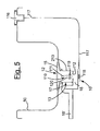
- sanitary facilities means elements such as sinks, wash-tubs, bidets or, preferably bath tubs, as shown for example in figure 1 and 5 .
- the quick-mounting water discharge group 10 for sanitary facilities 50 mentioned above comprises a first element 12, connectable, through a lower closure ring 40, in a non-removable manner with a hole 14 made in an eventual sanitary facility 50 and a second element 13 connectable without any of the adhesive substance to the closure ring 40 mentioned above during the assembling step of the group 10 itself.
- the first element 12 is mushroom-shaped and, as mentioned beforehand, it can be applied in a hole 14 advantageously made in a lower portion of the sanitary facility 50 for the passage of water from the sanitary 50 itself towards the outside.
- such first element 12 comprises a head portion 15 which, in use, is connectable to the internal wall of the sanitary facility 50 and shaped in a manner such that it covers substantially the related abovementioned hole 14 and to extend beyond it for a short section on the internal wall of the sanitary facility 50 mentioned above.
- a hollow tubular portion 16 has dimensions such that it extends beyond the lower wall of the sanitary facility 50 through the hole 14.
- the head portion 15 when mounted, does not make the hole 14 watertight but allows passage of water from the sanitary facility 50 into the tubular portion 16.
- the group 10 comprises, as mentioned beforehand, a lower closure ring 40, preferably provided with a sealing gasket 30, which is mounted laterally externally on a lower portion of the tubular portion 16 in a manner such that it abuts against the lower external wall of the sanitary facility 50 when the group 10 is mounted and installed.
- Such lower closure ring 40 and in particular one of its internal portion 42, can be screwed onto a lower portion of the tubular portion 16 projecting below the sanitary facility 50, when mounted.
- portions 15 and 16 of the mushroom-shaped element 12 can be integrally made, as previously described, or they can be two separate elements such as a conical body 16, equipped with a lower threaded end 46, and an upper covering cap 15.
- the quick-mounting water discharge group 10 for sanitary facilities 50 additionally comprises a second element 13 connectable of the lower closure ring 40 in a manner such that it is positioned, when mounted, below the sanitary facility 50.
- such second element 13 is a box-shaped element and it comprises a first upper opening 17 and at least a second upper water discharge opening 18 in which, during assembly of the group 10, the first upper opening 17 is connectable stably to the lower closure ring 40.
- the first upper opening 17 and the related portion of contact of the lower closure ring 40 can be snap-coupled due to the presence, on the ring 40, of an annular projection 41 equipped with a tooth-shaped end 20 capable of interlocking with the related annular seat 45 made on the external surface of the opening 17.
- the invention does not require advantageously the presence of any adhesive substance, for example silicon, thus reducing to zero the waiting time for laying operations of the sanitary facility 50 upon the first use of the same.
- the quick-mounting water discharge group 10 can comprise, in a preferred embodiment, also an improved discharge closure set 100 adapted to make the discharge pipe 18' selectively accessible with the water eventually contained inside the sanitary facility 50.
- FIG. 3a-4b An example of such discharge closure set 100 is shown in figures 3a-4b and comprises a plug 111 free to move between a first open position, raised, and a second closed position, lowered.
- such plug 111 cooperates with a discharge mouth 112 made upstream of the discharge opening 18 in a seat within the second element 13.
- the plug when in closed position the plug cooperates with the mouth 112 closing it completely and blocking any water penetrating into the group 10 from the sanitary facility 50 upstream of the mouth 112 itself and consequently upstream of the discharge opening 18.
- the second element 13 in fact internally contains two selectively communicating compartments in which the first is always connected through the first element 12 to the eventual sanitary facility 50, and in particular with the water contained therein, and the second compartment is always connected with the discharge pipe 18' through the opening 18.
- the portion of the plug 111 which cooperates with the mouth 112 is complementary to it and it is provided with a gasket 114 adapted to maintain the closure watertight, thus preventing the water present in the sanitary facility 50 from discharging into the discharge pipe 18'.
- the discharge closure set 100 is provided with opening/closing means 115 which cooperate with the plug 111 in order to move it to one of the two open or closed positions.
- the opening/closing means comprise a moveable element 118 moving between a first coupling position with said plug 111 and a second uncoupled position.
- the moveable element 118 is a first permanent magnet and the plug 111 comprises a second permanent magnet 119 of the same polarity which thus generates a repulsion effect against the moveable element 118.
- guide and stop means 120 are provided, such as upper and lower abutments, for which cooperate with the plug 111, in order to define and delimit the distance which can be covered by the same.
- Such guide and stop means 120 cooperate with the lower portion of the plug 111 in order to make a stop for the opening movement of the plug 111.
- the moveable element 118 of the opening/closing means 115 is preferably connected to actuation means 116 outside the sanitary facility 50 and arranged such that it can be activated by a user.
- the external actuation means 116 operate on the moveable element 118 to control its movement through suitable motion transmission means 117, such as for example a rigid rod connected to a lever 121 constrained to rotate around a pin 122.
- the moveable element 118 is positioned outside the discharge pipe 18' and therefore, the motion transmission means 117 do not have to come into contact with water.
- the moveable element 118 is brought by the motion transmission means 117 to a distal position with respect to the plug 111 so that there is substantially no coupling between the permanent magnet 119 provided for on the plug and the moveable element 118 itself.
- the plug 111 When in closed position, the plug 111 is at least partially inserted in the discharge mouth 112 and completely closes it in a substantially watertight manner.
- the discharge mouth section 112 of the second element 13 is preferably frustoconically shaped, with the larger base turned upwards, like the section of the plug portion complementary to the same. In such a manner, on one hand, greater interference and thus sealing between the plug 111 and such mouth 112 is ensured, while on the other hand the mouth 112 acts as a stop for the closing movement of the plug 111.
- the plug 111 rises, guided by the guide and stop means 120, until it interferes with the same, thus leaving the mouth 112 of the second element 13 at least partially open. Hence the water can flow into the discharge pipe 18' through the opening 18 of the second element 13.
- Figure 5 shows a bath tub 50 provided with the group 10 and discharge closure set 100 of sanitary facilities as they have been just described.
- the group 10 can also comprise at least a third 33 and fourth 34 opening, arranged substantially on the opposite side with respect to the second opening 18, which connect the group 10 to a filling limiting device for sanitary facilities 210.
- FIG. 6 A preferred embodiment of such filling limiting device 210 connected to the group 10 both mounted on a sanitary facility 50 is shown schematically in figure 6 .
- Such filling limiting device 210 comprises a first pipe 211 connectable at its first end 212 to the third opening 33 of the second element 13 upstream of the mouth 112 and connected at a second end 213 to a second pipe 214 for water drainage.
- the first pipe 211 is shaped in a manner such that its second end 213 is positioned at a higher elevation with respect to its first end 212.
- the second pipe 214 comprises a first end 215 connected to the second end 213 of the first pipe 211 and a second end 216 positioned at lower elevation than the first end 212 of the first pipe 211 and connected to the fourth opening 34 downstream of the mouth 112.
- a vent pipe 217 towards the environment is provided for.
- a vent control valve 219 is arranged and provided with a membrane 220 which allows exit and/or entry of air into the filling limiting device 210.
- the membrane has at least one coupling seat 222 with the open end 218 of the vent pipe 217 and is made of elastically deformable material in order to selectively make a sealed coupling with such end.
- the membrane is provided with a centrally-arranged, preferably cross-shaped cut 221; such membrane also advantageously is of negligible weight.
- the vent control valve 219 faces a wall of the sanitary facility 50 at the external actuation means 116 of the closure set 110 previously described. In such a manner, such valve 219 is concealed from sight and protected against clogging due to accumulation of dirt or any other sediment material.
- the plug 111 is inserted at least partially into the discharge mouth 12 and closes it in a substantially watertight manner.
- the filling tank 51 collects water up to a first maximum filling level delimitated by the elevation at which the first and the second pipe 211, 214 of the filling limiting device 210 join, as illustrated in figure 8a .
- the water 52 also reaches such level in the first pipe 211 of the filling limiting device 210. Once such level has been reached, the excess water tends to flow, pushed by the weight of the water 52 present in the filling tank 51, from the first pipe 211 of the filling limiting device 210 to the second pipe 214 of the same thus flowing towards the discharge 113 connected downstream of the second pipe 214.
- filling limiting device 210 can be employed even for sinks, wash-tubs, bidets or other similar facilities.
- the quick-mounting water discharge group 10 for sanitary facilities 50 comprises a first and second element 12, 13 alongside a lower closure ring 40.
- the first element 12 is mushroom-shaped and it can be mounted in a non-removable manner in the sanitary facility 50 in a hole 14 made in a lower portion of the same sanitary facility 50 itself.
- the lower closure ring 40 can be connected on the lower part to the first element 12 to maintain it in the abovementioned insertion position of the hole 14 of the sanitary facility 50.
- the second element 13 is a box-shaped element and it comprises a first upper opening 17 and at least a second water discharge opening 18, in which the first upper opening 17 can be snap-coupled with the lower closure ring 40 to create a water passage from the first element 12 to the second element 13 which in turn is selectively in communication with the discharge pipe 18'.
- connection between the second element 13 and the ring 40 is of snap-coupling type, no application of glue or silicon is required during the mounting step.
- the group 10 can advantageously comprise a control set of the opening 110 and a filling limiting device 210 as described previously in a manner to make an improved sanitary facility.
Landscapes
- Engineering & Computer Science (AREA)
- Environmental & Geological Engineering (AREA)
- Health & Medical Sciences (AREA)
- Life Sciences & Earth Sciences (AREA)
- Hydrology & Water Resources (AREA)
- Public Health (AREA)
- Water Supply & Treatment (AREA)
- Devices For Dispensing Beverages (AREA)
- Table Equipment (AREA)
- Bidet-Like Cleaning Device And Other Flush Toilet Accessories (AREA)
- Domestic Plumbing Installations (AREA)
Claims (17)
- Schnell montierbare Wasserabflussbaugruppe (10) für Sanitäreinrichtungen (50), umfassend ein erstes (12) und ein zweites Element (13), bei der das erste Element (12) pilzförmig ist, einen Kopfabschnitt (15) umfasst, mit einem Loch (14) der Sanitäreinrichtung (50) gekoppelt werden kann und einen hohlen Rohrabschnitt (16) aufweist, der mit dem Loch (14) gekoppelt werden kann und dessen hohler Rohrabschnitt (16) sich von dem Kopfabschnitt (15) weg erstreckt, wobei das zweite Element (13) ein kistenförmiges Element ist und eine erste obere Öffnung (17) und mindestens eine zweite Öffnung zum Wasserabfluss (18) umfasst,
dadurch gekennzeichnet, dass
die schnell montierbare Wasserabflussbaugruppe ferner einen unteren Schließring (40) umfasst, wobei der untere Schließring (40) entlang eines inneren Abschnitts (42) in einem unteren Abschnitt des hohlen Rohrabschnitts (16) eingeschränkt sein kann und an einem äußeren Abschnitt (41) des unteren Schließrings (40) mit der ersten oberen Öffnung (17) des zweiten Elements (13) über Einschnappen gekoppelt sein kann, um den Wasserdurchgang von dem ersten Element (12) zu dem zweiten Element (13) zu schaffen, wenn die Baugruppe (10) in dem Loch (14) der Sanitäreinrichtung (50) montiert ist, wobei der Kopfabschnitt (15) mit der Innenwand der Sanitäreinrichtung gekoppelt sein kann und gestaltet ist, um das Loch im Wesentlichen abzudecken. - Schnell montierbare Wasserabflussbaugruppe (10) für Sanitäreinrichtungen (50) nach Anspruch 1,
dadurch gekennzeichnet, dass
die Schnappkopplung durch ein zahnförmiges Ende (20) des äußeren Abschnitts (41) des Rings und einen zugehörigen ringförmigen Sitz (45) erreicht wird, der in einem oberen Abschnitt der ersten Öffnung (17) ausgebildet ist. - Schnell montierbare Wasserabflussbaugruppe (10) für Sanitäreinrichtungen (50) nach einem beliebigen der vorstehenden Ansprüche,
dadurch gekennzeichnet, dass
sie mit einem Abflussverschlusssatz (100) versehen ist, der von einem Anwender aktiviert werden kann. - Schnell montierbare Wasserabflussbaugruppe (10) für Sanitäreinrichtungen (50) nach dem vorstehenden Anspruch,
dadurch gekennzeichnet, dass
der Abschlussverschlusssatz (100) einen Stöpsel (111), der zwischen einer ersten offenen Position und einer zweiten geschlossenen Position frei beweglich ist, und Öffnungs-/Schließmittel (115) umfasst, die zur Zusammenarbeit mit dem Stöpsel (111) ausgelegt sind, um ihn in eine der zwei offenen oder geschlossenen Positionen zu bewegen, wobei die Öffnungs-/Schließmittel (115) mindestens ein Element (118) umfassen, das zwischen einer ersten Koppelposition mit dem Stöpsel (111) und einer zweiten entkoppelten Position beweglich ist, dadurch gekennzeichnet, dass das bewegliche Element (118) und der Stößel (111) in der ersten Koppelposition magnetisch gekoppelt sind. - Schnell montierbare Wasserabflussbaugruppe (10) für Sanitäreinrichtungen (50) nach Anspruch 4,
dadurch gekennzeichnet, dass
der Stöpsel (111) mindestens einen ersten Permanentmagnet (119) umfasst und das bewegliche Element (118) mindestens einen zweiten Permanentmagnet umfasst, wobei der erste und zweite Permanentmagnet die gleiche Polarität aufweisen. - Schnell montierbare Wasserabflussbaugruppe (10) für Sanitäreinrichtungen (50) nach Anspruch 4 oder 5,
dadurch gekennzeichnet, dass
sie Führungs- und Stoppmittel (120) zur Definition und Beschränkung des Wegs des Stöpsels (111) umfasst. - Schnell montierbare Wasserabflussbaugruppe (10) für Sanitäreinrichtungen (50) nach Anspruch 6,
dadurch gekennzeichnet, dass
die Führungs- und Stoppmittel (120) mit einem unteren Abschnitt des Stöpsels (111) angrenzend zusammenwirken. - Schnell montierbare Wasserabflussbaugruppe (10) für Sanitäreinrichtungen (50) nach einem der Ansprüche 4 bis 7,
dadurch gekennzeichnet, dass
die Öffnungs-/Schließmittel (115) ein Betätigungsmittel (116) umfassen, das von außen zugänglich ist und mit dem beweglichen Element (118) durch Bewegungsübertragungsmittel (117) verbunden ist. - Schnell montierbare Wasserabflussbaugruppe (10) für Sanitäreinrichtungen (50) nach Anspruch 8,
dadurch gekennzeichnet, dass
die Bewegungsübertragungsmittel (117) eine Stange umfassen, die stromabwärts mit einem Hebel (121) verbunden ist, der auf eine Drehung um einen Stift (122) herum eingeschränkt ist, wobei der Hebel (121) eine translatorische Bewegung an das bewegliche Element (118) überträgt. - Schnell montierbare Wasserabflussbaugruppe (10) für Sanitäreinrichtungen (50) nach einem beliebigen der vorstehenden Ansprüche,
dadurch gekennzeichnet, dass
sie eine dritte und eine vierte Öffnung (33, 34) umfasst. - Sanitäreinrichtung (50), die ein Beckenelement (51) umfasst, das mit einer Abflussöffnung versehen ist, die selektiv versperrt werden kann,
dadurch gekennzeichnet, dass
sie eine schnell montierbare Wasserabflussbaugruppe (10) nach einem beliebigen der vorstehenden Ansprüche umfasst. - Sanitäreinrichtung (50) nach dem vorstehenden Anspruch,
die, wenn sie von Anspruch 10 abhängt, eine Füllungsbegrenzungseinrichtung (210) umfasst. - Sanitäreinrichtung (50) nach dem vorstehenden Anspruch,
dadurch gekennzeichnet, dass
die Füllungsbegrenzungseinrichtung (210) für Sanitäreinrichtungen (50) ein erstes Rohr (211) umfasst, das an seinem ersten Ende (212) mit der Basis einer Füllungsbegrenzungseinrichtung (51) der Sanitäreinrichtung (50) verbunden werden kann, und das an einem seiner zweiten Enden (213) mit einem zweiten Rohr (214) zum Wasserablauf verbunden ist, wobei das erste Rohr (211) derart geformt ist, dass sein zweites Ende (213) auf einer größeren Höhe als sein erstes Ende (212) positioniert ist, wobei das zweite Rohr (214) ein erstes Ende (215), das mit dem zweiten Ende (213) des ersten Rohrs (211) verbunden ist, und ein zweites Ende (216) umfasst, das auf einer niedrigeren Höhe als das erste Ende (212) des ersten Rohrs (211) positioniert ist, wobei an der Verbindung zwischen dem zweiten Ende (213) des ersten Rohrs (211) und dem ersten Ende (215) des zweiten Rohrs (214) ein Entlüftungsrohr (217) an die Umgebung bereitgestellt ist, das an einem seiner offenen Enden (218) mit einem Entlüftungssteuerungsventil (219) für den Austritt und/oder Eintritt von Luft versehen ist. - Sanitäreinrichtung (50) nach Anspruch 13,
dadurch gekennzeichnet, dass
das Entlüftungssteuerungsventil (219) eine mit einem Schnitt (221) versehene Membran (220) umfasst. - Sanitäreinrichtung (50) nach Anspruch 14,
dadurch gekennzeichnet, dass
der Schnitt (221) der Membran (220) kreuzförmig ist und mit Bezug auf diese in der Mitte angeordnet ist. - Sanitäreinrichtung (50) nach Anspruch 14 oder 15,
dadurch gekennzeichnet, dass
die Membran (220) aus einem elastisch verformbaren Material hergestellt ist und einen Sitz (222) zur Kopplung mit dem offenen Ende (218) des Entlüftungsrohrs umfasst. - Sanitäreinrichtung (50) nach Anspruch 14 oder 16,
dadurch gekennzeichnet, dass
die Membran (220) ein vernachlässigbares Gewicht aufweist.
Applications Claiming Priority (1)
| Application Number | Priority Date | Filing Date | Title |
|---|---|---|---|
| ITMI20071777 ITMI20071777A1 (it) | 2007-09-14 | 2007-09-14 | Gruppo di scarico d'acqua a montaggio rapido per sanitari e sanitari impieganti tale gruppo |
Publications (2)
| Publication Number | Publication Date |
|---|---|
| EP2037049A1 EP2037049A1 (de) | 2009-03-18 |
| EP2037049B1 true EP2037049B1 (de) | 2010-07-21 |
Family
ID=40010992
Family Applications (1)
| Application Number | Title | Priority Date | Filing Date |
|---|---|---|---|
| EP20070123508 Active EP2037049B1 (de) | 2007-09-14 | 2007-12-18 | Schnell montierbare Wasserabflussbaugruppe für Sanitäreinrichtungen und Sanitäreinrichtung mit einer solchen Baugruppe |
Country Status (3)
| Country | Link |
|---|---|
| EP (1) | EP2037049B1 (de) |
| DE (1) | DE602007007950D1 (de) |
| IT (1) | ITMI20071777A1 (de) |
Families Citing this family (2)
| Publication number | Priority date | Publication date | Assignee | Title |
|---|---|---|---|---|
| CN103830095B (zh) * | 2014-03-11 | 2015-07-15 | 桂林康兴医疗器械有限公司 | 一种磁力密合排水装置及带磁力密合排水装置的坐浴盆 |
| FR3032731A1 (fr) * | 2015-02-16 | 2016-08-19 | Wirquin Plastiques Sa | Ensemble d'evacuation d'eau, comprenant une piece tubulaire fixee a un appareil sanitaire par un ecrou, l'ecrou etant concu pour supporter un corps de bonde |
Family Cites Families (3)
| Publication number | Priority date | Publication date | Assignee | Title |
|---|---|---|---|---|
| FI70063B (fi) * | 1985-04-10 | 1986-01-31 | Kalevi Saentti | Flaskvattenlaos |
| US6675406B2 (en) * | 2000-06-13 | 2004-01-13 | Wcm Industries, Inc. | Overflow assembly for bathtubs and the like |
| ITVI20040305A1 (it) * | 2004-12-23 | 2005-03-23 | Paolo Moresco | Dispositivo di drenaggio e scarico per liquidi, applicabile a vasche ed idrosanitari |
-
2007
- 2007-09-14 IT ITMI20071777 patent/ITMI20071777A1/it unknown
- 2007-12-18 EP EP20070123508 patent/EP2037049B1/de active Active
- 2007-12-18 DE DE200760007950 patent/DE602007007950D1/de active Active
Also Published As
| Publication number | Publication date |
|---|---|
| EP2037049A1 (de) | 2009-03-18 |
| DE602007007950D1 (de) | 2010-09-02 |
| ITMI20071777A1 (it) | 2009-03-15 |
Similar Documents
| Publication | Publication Date | Title |
|---|---|---|
| EP2037050B1 (de) | Abflussverschlussvorrichtung für Sanitäreinrichtungen und Sanitäreinrichtung mit dem Abflussverschlussvorrichtung | |
| US8176580B2 (en) | Diverter spout | |
| US11885432B2 (en) | Rigid piston valve incorporating a solenoid | |
| MXPA06009455A (es) | Ensamble de cierre para drenaje de bano. | |
| RU2743254C1 (ru) | Спускной клапан для сливного бачка сантехнического устройства | |
| EP2037051A2 (de) | Verborgene Füllungsbegrenzungsvorrichtung für Sanitäreinrichtungen und Sanitäreinrichtung damit | |
| EP2037049B1 (de) | Schnell montierbare Wasserabflussbaugruppe für Sanitäreinrichtungen und Sanitäreinrichtung mit einer solchen Baugruppe | |
| CA2926927C (en) | Push-activated tub spout | |
| US8584909B2 (en) | Dispensing tap for beverages | |
| EP1426505A3 (de) | Universeller Spender für Desinfektionsflüssigkeit für Wasserbehälter o. ä., insbesondere für Spülkästen für Toiletten | |
| US9222584B2 (en) | Rigid piston retrofit for a diaphragm flush valve | |
| US7003813B1 (en) | Two-way valve for dispensing liquids | |
| WO2026080816A1 (en) | Disconnecting linkage for flushing | |
| KR20020022571A (ko) | 캡 | |
| JP4941982B2 (ja) | オーバーフロー口の開閉構造 | |
| EP3452666B1 (de) | Betätigung für spülventil | |
| WO2006113851A3 (en) | Automatic flush toilet tank assembly | |
| GB2579363A (en) | Fill valve assembly | |
| WO2006094331A1 (en) | A cistern inlet valve assembly | |
| GB2389040A (en) | Overflow preventer | |
| CA2568327A1 (en) | Flow control valve | |
| CZ9448U1 (cs) | Napouštěcí ventil |
Legal Events
| Date | Code | Title | Description |
|---|---|---|---|
| PUAI | Public reference made under article 153(3) epc to a published international application that has entered the european phase |
Free format text: ORIGINAL CODE: 0009012 |
|
| AK | Designated contracting states |
Kind code of ref document: A1 Designated state(s): AT BE BG CH CY CZ DE DK EE ES FI FR GB GR HU IE IS IT LI LT LU LV MC MT NL PL PT RO SE SI SK TR |
|
| AX | Request for extension of the european patent |
Extension state: AL BA HR MK RS |
|
| 17P | Request for examination filed |
Effective date: 20090902 |
|
| AKX | Designation fees paid |
Designated state(s): DE FR GB |
|
| GRAP | Despatch of communication of intention to grant a patent |
Free format text: ORIGINAL CODE: EPIDOSNIGR1 |
|
| RAP1 | Party data changed (applicant data changed or rights of an application transferred) |
Owner name: IDEAL STANDARD INTERNATIONAL BVBA |
|
| GRAS | Grant fee paid |
Free format text: ORIGINAL CODE: EPIDOSNIGR3 |
|
| GRAA | (expected) grant |
Free format text: ORIGINAL CODE: 0009210 |
|
| AK | Designated contracting states |
Kind code of ref document: B1 Designated state(s): DE FR GB |
|
| REG | Reference to a national code |
Ref country code: GB Ref legal event code: FG4D |
|
| REF | Corresponds to: |
Ref document number: 602007007950 Country of ref document: DE Date of ref document: 20100902 Kind code of ref document: P |
|
| PLBE | No opposition filed within time limit |
Free format text: ORIGINAL CODE: 0009261 |
|
| STAA | Information on the status of an ep patent application or granted ep patent |
Free format text: STATUS: NO OPPOSITION FILED WITHIN TIME LIMIT |
|
| 26N | No opposition filed |
Effective date: 20110426 |
|
| REG | Reference to a national code |
Ref country code: DE Ref legal event code: R097 Ref document number: 602007007950 Country of ref document: DE Effective date: 20110426 |
|
| REG | Reference to a national code |
Ref country code: FR Ref legal event code: PLFP Year of fee payment: 9 |
|
| REG | Reference to a national code |
Ref country code: FR Ref legal event code: PLFP Year of fee payment: 10 |
|
| REG | Reference to a national code |
Ref country code: FR Ref legal event code: PLFP Year of fee payment: 11 |
|
| PGFP | Annual fee paid to national office [announced via postgrant information from national office to epo] |
Ref country code: GB Payment date: 20251229 Year of fee payment: 19 |
|
| PGFP | Annual fee paid to national office [announced via postgrant information from national office to epo] |
Ref country code: FR Payment date: 20251226 Year of fee payment: 19 |
|
| PGFP | Annual fee paid to national office [announced via postgrant information from national office to epo] |
Ref country code: DE Payment date: 20251229 Year of fee payment: 19 |