EP2037074A2 - Dispositif d'obscurcissement au moins partiel - Google Patents
Dispositif d'obscurcissement au moins partiel Download PDFInfo
- Publication number
- EP2037074A2 EP2037074A2 EP08164247A EP08164247A EP2037074A2 EP 2037074 A2 EP2037074 A2 EP 2037074A2 EP 08164247 A EP08164247 A EP 08164247A EP 08164247 A EP08164247 A EP 08164247A EP 2037074 A2 EP2037074 A2 EP 2037074A2
- Authority
- EP
- European Patent Office
- Prior art keywords
- rail
- holding
- fastening means
- holding element
- holding elements
- Prior art date
- Legal status (The legal status is an assumption and is not a legal conclusion. Google has not performed a legal analysis and makes no representation as to the accuracy of the status listed.)
- Withdrawn
Links
- 239000000463 material Substances 0.000 claims abstract description 7
- 239000004697 Polyetherimide Substances 0.000 claims abstract description 6
- 229920001601 polyetherimide Polymers 0.000 claims abstract description 6
- 229920003002 synthetic resin Polymers 0.000 claims abstract description 5
- 239000000057 synthetic resin Substances 0.000 claims abstract description 5
- 238000006073 displacement reaction Methods 0.000 claims description 2
- 239000004417 polycarbonate Substances 0.000 claims description 2
- 229920000515 polycarbonate Polymers 0.000 claims description 2
- 230000014759 maintenance of location Effects 0.000 abstract 1
- 238000005452 bending Methods 0.000 description 4
- 238000009434 installation Methods 0.000 description 2
- 239000011324 bead Substances 0.000 description 1
- 239000011521 glass Substances 0.000 description 1
- 230000001771 impaired effect Effects 0.000 description 1
- 239000012535 impurity Substances 0.000 description 1
- 238000000034 method Methods 0.000 description 1
- 238000007665 sagging Methods 0.000 description 1
Images


Classifications
-
- E—FIXED CONSTRUCTIONS
- E06—DOORS, WINDOWS, SHUTTERS, OR ROLLER BLINDS IN GENERAL; LADDERS
- E06B—FIXED OR MOVABLE CLOSURES FOR OPENINGS IN BUILDINGS, VEHICLES, FENCES OR LIKE ENCLOSURES IN GENERAL, e.g. DOORS, WINDOWS, BLINDS, GATES
- E06B9/00—Screening or protective devices for wall or similar openings, with or without operating or securing mechanisms; Closures of similar construction
- E06B9/24—Screens or other constructions affording protection against light, especially against sunshine; Similar screens for privacy or appearance; Slat blinds
- E06B9/26—Lamellar or like blinds, e.g. venetian blinds
- E06B9/262—Lamellar or like blinds, e.g. venetian blinds with flexibly-interconnected horizontal or vertical strips; Concertina blinds, i.e. upwardly folding flexible screens
-
- E—FIXED CONSTRUCTIONS
- E06—DOORS, WINDOWS, SHUTTERS, OR ROLLER BLINDS IN GENERAL; LADDERS
- E06B—FIXED OR MOVABLE CLOSURES FOR OPENINGS IN BUILDINGS, VEHICLES, FENCES OR LIKE ENCLOSURES IN GENERAL, e.g. DOORS, WINDOWS, BLINDS, GATES
- E06B9/00—Screening or protective devices for wall or similar openings, with or without operating or securing mechanisms; Closures of similar construction
- E06B9/24—Screens or other constructions affording protection against light, especially against sunshine; Similar screens for privacy or appearance; Slat blinds
- E06B9/26—Lamellar or like blinds, e.g. venetian blinds
- E06B9/28—Lamellar or like blinds, e.g. venetian blinds with horizontal lamellae, e.g. non-liftable
- E06B9/30—Lamellar or like blinds, e.g. venetian blinds with horizontal lamellae, e.g. non-liftable liftable
- E06B9/32—Operating, guiding, or securing devices therefor
- E06B9/327—Guides for raisable lamellar blinds with horizontal lamellae
-
- E—FIXED CONSTRUCTIONS
- E06—DOORS, WINDOWS, SHUTTERS, OR ROLLER BLINDS IN GENERAL; LADDERS
- E06B—FIXED OR MOVABLE CLOSURES FOR OPENINGS IN BUILDINGS, VEHICLES, FENCES OR LIKE ENCLOSURES IN GENERAL, e.g. DOORS, WINDOWS, BLINDS, GATES
- E06B9/00—Screening or protective devices for wall or similar openings, with or without operating or securing mechanisms; Closures of similar construction
- E06B9/24—Screens or other constructions affording protection against light, especially against sunshine; Similar screens for privacy or appearance; Slat blinds
- E06B9/26—Lamellar or like blinds, e.g. venetian blinds
- E06B9/262—Lamellar or like blinds, e.g. venetian blinds with flexibly-interconnected horizontal or vertical strips; Concertina blinds, i.e. upwardly folding flexible screens
- E06B2009/2625—Pleated screens, e.g. concertina- or accordion-like
Definitions
- the invention relates to a device, in particular pleated blind or blind, for at least partial shading with a first rail and a second rail, with a shading element arranged between the first rail and the second rail, with elongated first holding elements on which the first rail and the second rail are slidably held, wherein the first holding elements are arranged at right angles to the longitudinal axis of the rails at the opposite ends of the rails.
- Such a device is known from WO 2007/056781 A1 known.
- Such devices are used to at least partially cover openings of buildings. For example, pleats or blinds can reduce the incidence of light and / or serve as a screen.
- the devices are used, for example, in conjunction with windows or doors.
- the devices can also be used to delimit areas of space within a building.
- the window openings can be covered completely or even partially by means of the device. Due to the sliding first and second rail manifold adjustment options are given. Thus, for example, in the case of a window or a door, only the upper part of the opening can be covered, so that light can continue to be incident through the lower part of the opening, and thus only partial shading is achieved.
- the disadvantage here is that the rails can bend due to their total weight. Since the rails are held only laterally displaceable by means of the elongated first holding elements, the rails can bend in the middle. Especially when using a blind additional components must be included in at least one rail with, for example, to allow the adjustment of the individual slats. Due to the additional components, the weight of the rail inevitably increases. As a result, the risk of self-adjusting deflection of the rail is increased due to the greater total weight. Especially with wide openings to be covered there is a risk that the functionality of the device is impaired due to the sagging rails. As a result, the operation of the device can be disturbed to the point of uselessness.
- the problem underlying the invention is therefore to develop the aforementioned device such that a bending of the rails can be reliably avoided.
- the problem is solved by means of a device of the aforementioned type in that between the first holding elements at least one elongated second holding element is arranged at right angles to the longitudinal axis of the rails, wherein the first rail and / or the second rail is slidably held on the second holding element.
- the weight of the rails no longer needs to be borne solely by the first laterally arranged on the rail ends holding elements. Rather, the weight is now distributed to the first holding elements and the second holding element. Furthermore, a bending of the rails is thereby reliably avoided, that the second holding element is arranged between the first holding elements.
- the second holding element is arranged centrally between the first holding elements.
- a rail held at the outer ends undergoes its greatest deflection in the middle of the rail, since here the holding forces acting on the rail ends have the least influence.
- the particular arrangement that is particularly susceptible to deflection is used as an additional breakpoint by the central arrangement of the second holding element.
- several second holding elements for example, depending on the width of the device can be used. This makes it possible to use, for example, pleats or blinds with virtually any rail length or width of the device.
- a holding force acts from the second holding element on the first rail.
- the first rail if it is for example the upper rail, may have a higher total weight than the second rail, which may be a lower rail, due to additional components. Due to the additional holding force bending of the first and heavier rail can be reliably avoided. As a result, a permanent functioning of the device is ensured.
- one, in particular four, deflections are assigned to the second holding element in the first rail.
- the deflections are protected due to the arrangement in the first rail from disturbing influences such as impurities.
- further, in particular four, deflections are provided in the second rail for the second holding element.
- the second holding element can also be guided expediently with respect to the second rail.
- the second holding element is guided at right angles to the longitudinal axis of the second rail through a first opening in the second rail.
- the supply of the second holding element to the second rail is clearly defined and defined.
- the second holding element is guided by means of a first deflection in the longitudinal direction of the second rail and in the direction of the remote rail end and by means of a second deflection at right angles to the longitudinal axis of the second rail through a second opening from the second rail in the direction of the first rail.
- the leadership of the second holding element within the second rail and with respect to the deflection provided there is clearly defined. Due to this guidance acts in the area of second deflection a holding force on the second rail. This reduces the risk of deflection of the second rail.
- the second holding element is guided at right angles to the longitudinal axis of the first rail through a third opening in the first rail. Through the third opening, the supply of the second holding element is clearly defined and fixed in the first rail.
- the second holding element is guided by means of a third deflection in the longitudinal direction of the first rail and in the direction of the remote rail end and by means of a fourth deflection at right angles to the longitudinal axis of the first rail through a fourth opening from the first rail. Due to the previously given guidance of the second holding element results that in the region of the fourth deflection an additional holding force acts on the first rail.
- the first rail and / or second rail is held displaceable by means of the second holding element in addition to the first holding elements.
- the deflections are made of synthetic resin material, in particular high-strength polyetherimide (PEI).
- PEI polyetherimide
- the risk of wear and material fatigue can be significantly reduced.
- a durable and reliable operation of the device is favored.
- the second holding element is guided through openings of the shading element. This makes it possible to reliably fix the position of the shading element between the first rail and the second rail. This ensures that the shading element does not emerge or bulge out of a plane imagined between the first rail and the second rail, for example due to a gust of wind.
- additional third holding elements are provided in addition to the first holding elements and the second holding element.
- the third holding elements may be provided for additional guidance of the shading element. As a result, the position of the shading element between the first rail and the second rail can be determined.
- the holding elements are cord-like, in particular designed as cords.
- strings as holding elements in devices of the type mentioned is known and proven. By using such cords, the functionality of the device is permanently guaranteed.
- the first holding elements on a C-threading preferably have a Z-threading.
- Such threading techniques have proven useful when used in pleats or blinds.
- the first rail and the second rail are preferably displaceable independently of one another, in particular relative to one another, along the retaining elements. This results in a particularly wide variety of possible settings. Thus, for example, windows or doors can be partially or completely covered not only from above, but it is also possible to cover such openings only in a lower or central area.
- fastening means are provided for the holding elements. This makes it possible to pre-assemble the device as far as possible. When installing the device only the fasteners need to be attached. The easier assembly reduces the cost and the risk of adjustment errors.
- fastening means are assigned to the mutually remote ends of the rails and spaced at right angles from the rails in the displacement direction, wherein the fastening means are preferably arranged on an inner reveal.
- the fastening means can be attached to the glazing beads of a window or door.
- a further fastening means is provided for the second retaining element, and preferably the further fastening means is arranged centrally between the first fastening means, in particular facing the first rail.
- a first fastening means are designed as a starting point and a second fastening means as an end point for the retaining element, and preferably the starting point and the end point correspond to the fastening means facing the second rail.
- the starting point and end point of the second holding element are clearly defined.
- the holding element is guided from the starting point via the second rail to the first rail. Will from the first rail the second holding element is guided to the further fastening means in order subsequently to be guided again by the further fastening means to the first rail. Subsequently, the second holding element is guided from the first rail to the second rail and finally via the second rail to the end point.
- the second holding element by means of the further fastening means, in particular by 180 °, deflected. Only because of such a deflection can the second holding element be returned from the starting point to the end point.
- the, in particular the further, fastening means made of synthetic resin material, in particular polycarbonate, are produced.
- the processing of such materials is known and proven.
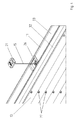
- Fig. 1 shows a device 10 according to the invention, wherein the device 10 is formed here as a pleat 10.
- the device 10 may also be a venetian blind.
- the device 10 has a first rail 11 and a second rail 12. Between the first rail 11 and the second rail 12, a shading element 13 is arranged.
- the shading element 13 is a pleated element 13.
- the device 10 has first elongate retaining elements 14, on which the first rail 11 and the second rail 12 are held displaceably.
- the first holding elements 14 are at right angles to the longitudinal axis of the rails 11, 12 at the opposite ends Ends of the rails 11, 12 are arranged.
- an elongate second holding element 15 is arranged at right angles to the longitudinal axis of the rails 11, 12.
- the second holding element 15 is arranged centrally and at equal distances from the mutually remote ends of the rails 11, 12.
- the device 10 has third holding elements 16.
- All retaining elements 14, 15, 16 are associated with a first fastening means 17 and a second fastening means 18.
- the first holding elements 14 and third holding elements 16 are associated with a third fastening means 19 and a fourth fastening means 20.
- the second holding element 15, however, is associated with a further fastening means 21.
- the fastening means 17, 18, 19, 20, 21 are attached to a glass strips, not shown, for example, a window in a known manner.
- the shading element 13 has a plurality of openings 22, through which the holding elements 14, 15, 16 are guided.
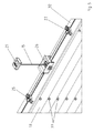
- Fig. 2 1 shows a schematic representation of the device 10 according to the invention and illustrates a possible guidance of the retaining elements 14, 15 and 16.
- the first retaining elements 14 are guided in a known C-threading from the fastening means 17 to the fastening means 19 or from the fastening means 18 to the fastening means 20.
- the third holding elements 16 are guided by means of a likewise known Z-threading from the fastening means 17 to the fastening means 20 and from the fastening means 18 to the fastening means 19. In this case, two deflections occur within the first rail 11 and the second rail 12.
- the second holding element 15 is introduced starting from the fastening means 17 through an opening 23 in the second rail 12.
- the second holding element 15 is guided in the longitudinal direction of the second rail 12 and in the direction of the remote rail end.
- the second holding element 15 is guided by means of a second deflection at right angles to the longitudinal axis of the second rail 15 through a second opening 24 from the second rail 12 in the direction of the first rail 11.
- the second holding element 15 is guided by apertures 22 of the shading element 13, not shown here, in order to then be guided through an opening 25 in the first rail 11. There, the second holding element 15 is guided by means of a third deflection in the longitudinal direction of the first rail 11 and in the direction of the rail center and by means of a fourth deflection at right angles to Longitudinal axis of the first rail 11 is guided by a fourth opening 26 from the first rail 11.
- the second holding element 15 is then guided to the further fastening means 21 and deflected there by 180 °.
- the second holding member 15 is returned again in the direction of the opening 26 and in the first rail 11, to then be guided over a further deflection in the longitudinal direction of the first rail 11 and from the opening 25 away.
- the second holding element 15 is guided by means of a further deflection through an opening 27 from the first rail 11 in the direction of the second rail 12.
- the second retaining element 15 re-enters the second rail 12 via an opening 28.
- a deflection first takes place from the opening 24 away from the rail end, in order then to be guided via a further deflection out of the opening 29 out of the second rail 12 and in the direction of the fastening means 18.
- the third holding elements 16 are held by spring compressor 30 to tension.
- the required tension for the holding elements 14, 16 is effected and inaccuracies in the installation of the device 10 can be compensated.
- the Fig. 3 illustrates another possible threading of the holding elements 14, 15 and 16. While the openings 24, 25, 27 and 28 according to the Fig. 2 are arranged in a central region of the first rail 11 and the second rail 12, the openings 24, 25, 27 and 28 are according to the Fig. 3 arranged in an edge region of the rails.
- the Fig. 4 shows a section of the perspective side view according to the Fig. 1 and illustrates how the second holding member 15 is guided out of the opening 26 in the direction of the further fastening means 21 and from this again back to the opening 26. Furthermore, it can be seen that the first rail 11 consists of a base rail 32 and a cover rail 33.
- the Fig. 5 shows the section according to the Fig. 4 This now shows how the second holding element 15 is initially deflected through the opening 25 in the direction of the opening 26 in order to be guided in the direction of the further fastening means 21 after renewed deflection. After the 180 ° deflection by means of the further fastening means 21, the second holding element 15 is again guided through the opening 26 and now in the direction of the opening 27.
Landscapes
- Engineering & Computer Science (AREA)
- Structural Engineering (AREA)
- Architecture (AREA)
- Civil Engineering (AREA)
- Blinds (AREA)
Applications Claiming Priority (1)
| Application Number | Priority Date | Filing Date | Title |
|---|---|---|---|
| DE102007043952A DE102007043952A1 (de) | 2007-09-14 | 2007-09-14 | Vorrichtung zum mindestens teilweisen Verschatten |
Publications (2)
| Publication Number | Publication Date |
|---|---|
| EP2037074A2 true EP2037074A2 (fr) | 2009-03-18 |
| EP2037074A3 EP2037074A3 (fr) | 2013-12-25 |
Family
ID=40120080
Family Applications (1)
| Application Number | Title | Priority Date | Filing Date |
|---|---|---|---|
| EP08164247.2A Withdrawn EP2037074A3 (fr) | 2007-09-14 | 2008-09-12 | Dispositif d'obscurcissement au moins partiel |
Country Status (2)
| Country | Link |
|---|---|
| EP (1) | EP2037074A3 (fr) |
| DE (1) | DE102007043952A1 (fr) |
Cited By (1)
| Publication number | Priority date | Publication date | Assignee | Title |
|---|---|---|---|---|
| EP2295702A3 (fr) * | 2009-08-12 | 2016-11-09 | VKR Holding A/S | Écran pour fenêtre |
Families Citing this family (2)
| Publication number | Priority date | Publication date | Assignee | Title |
|---|---|---|---|---|
| DE102011053648A1 (de) | 2011-09-15 | 2013-03-21 | Achim Lienert | Schnurspanner zum Spannen einer Schnur an Beschattungsanlagen |
| DE102011057147A1 (de) | 2011-12-29 | 2013-07-04 | Achim Lienert | Beschattungsanlage mit horizontalen Faltlamellen |
Citations (1)
| Publication number | Priority date | Publication date | Assignee | Title |
|---|---|---|---|---|
| WO2007056781A1 (fr) | 2005-11-15 | 2007-05-24 | Bernhard Feistritzer | Moyen pour faire au moins partiellement ecran a un rayonnement ou a la vue |
Family Cites Families (5)
| Publication number | Priority date | Publication date | Assignee | Title |
|---|---|---|---|---|
| EP0195483B1 (fr) * | 1985-03-13 | 1991-03-06 | Schön B.V. | Store pliant, store pliant composite et barre d'assemblage |
| JP2749473B2 (ja) * | 1991-12-26 | 1998-05-13 | 株式会社メタコ | ワイヤー・テンション・システムによるプリーツ状スクリーン装置 |
| EP0674091B1 (fr) * | 1994-03-08 | 1999-11-03 | Hunter Douglas Industries B.V. | Store ou jalousie rétractable |
| DE29702174U1 (de) * | 1997-02-08 | 1998-07-09 | Hüppe Form Sonnenschutzsysteme GmbH, 26133 Oldenburg | Faltjalousie |
| DE202006009738U1 (de) * | 2006-02-10 | 2006-09-21 | PARAT Automotive Schönenbach GmbH + Co. KG | Führungsanordnung für einen Querriegel eines Abschattungsmittels |
-
2007
- 2007-09-14 DE DE102007043952A patent/DE102007043952A1/de active Pending
-
2008
- 2008-09-12 EP EP08164247.2A patent/EP2037074A3/fr not_active Withdrawn
Patent Citations (1)
| Publication number | Priority date | Publication date | Assignee | Title |
|---|---|---|---|---|
| WO2007056781A1 (fr) | 2005-11-15 | 2007-05-24 | Bernhard Feistritzer | Moyen pour faire au moins partiellement ecran a un rayonnement ou a la vue |
Cited By (1)
| Publication number | Priority date | Publication date | Assignee | Title |
|---|---|---|---|---|
| EP2295702A3 (fr) * | 2009-08-12 | 2016-11-09 | VKR Holding A/S | Écran pour fenêtre |
Also Published As
| Publication number | Publication date |
|---|---|
| DE102007043952A1 (de) | 2009-04-09 |
| EP2037074A3 (fr) | 2013-12-25 |
Similar Documents
| Publication | Publication Date | Title |
|---|---|---|
| DE102010018259B4 (de) | Fahrzeugrolloanordnung, Baugruppe mit einer Fahrzeugrolloanordnung, und Dachanordnung | |
| EP4030031A1 (fr) | Dispositif de blindage | |
| EP2037074A2 (fr) | Dispositif d'obscurcissement au moins partiel | |
| EP1783318B1 (fr) | Tensionneur de cordes pour tensionner les cordes des dispositfs d'ombrage et dispositif d'ombrage | |
| DE102013008597A1 (de) | Montagesystem zur Befestigung von Führungsschienen | |
| EP1783315A2 (fr) | Support de cordon et capuchon d'extrémité pour une jalousie | |
| DE202009015473U1 (de) | Lamellenjalousie | |
| EP1898041B1 (fr) | Procedé et dispositif de montage d'accessoires sur cadres de bâtiments | |
| EP3929396B1 (fr) | Insert de guidage pour un rail de guidage d'un système de rideau, rail de guidage pour système de rideau et système de rideau permettant de guider un rideau | |
| AT517909B1 (de) | Schutzvorrichtung | |
| DE3048333C2 (de) | Halterungsvorrichtung für ein Springrollo | |
| DE202016102098U1 (de) | Plisseeanlage mit Magnetelement | |
| AT516524B1 (de) | Insektenschutzsystem | |
| EP4474610B1 (fr) | Dispositif de protection pour une ouverture de bâtiment et ouverture de bâtiment dotée d'un tel dispositif de protection | |
| EP1327742B1 (fr) | Rideau pour surfaces non rectangulaires | |
| DE20210855U1 (de) | Rollovorrichtung | |
| DE102019132564B4 (de) | Positioniereinrichtung und Sonnen-oder Blickschutzeinrichtung mit einer solchen Positioniereinrichtung | |
| DE10050176B4 (de) | Einrastbare Führungsschiene | |
| EP4717870A1 (fr) | Dispositif de protection contre le soleil et/ou la vision | |
| CH717723A2 (de) | Plissee-Sonnenschutzsystem. | |
| DE1509794C (de) | Lamellenraffjalousie, deren Lamellen in seitlichen Führungsschienen gefuhrt und an ihren Enden jeweils durch ein zusammen klappbares Gelenkband miteinander verbun den sind | |
| DE102019103358A1 (de) | Plissee-Sonnenschutzsystem | |
| DE19858961A1 (de) | Spanneckverbinderelement für scheibenintegrierte Sonnenschutzsysteme | |
| DE102022106392A1 (de) | Abschlussschild zur anbringung an einer vorlaufkante eines torbehangs | |
| DE202005003668U1 (de) | Lamelle einer Jalousie bzw. eines Raffstores |
Legal Events
| Date | Code | Title | Description |
|---|---|---|---|
| PUAI | Public reference made under article 153(3) epc to a published international application that has entered the european phase |
Free format text: ORIGINAL CODE: 0009012 |
|
| AK | Designated contracting states |
Kind code of ref document: A2 Designated state(s): AT BE BG CH CY CZ DE DK EE ES FI FR GB GR HR HU IE IS IT LI LT LU LV MC MT NL NO PL PT RO SE SI SK TR |
|
| AX | Request for extension of the european patent |
Extension state: AL BA MK RS |
|
| RAP1 | Party data changed (applicant data changed or rights of an application transferred) |
Owner name: HUNTER DOUGLAS INDUSTRIES SWITZERLAND GMBH |
|
| PUAL | Search report despatched |
Free format text: ORIGINAL CODE: 0009013 |
|
| AK | Designated contracting states |
Kind code of ref document: A3 Designated state(s): AT BE BG CH CY CZ DE DK EE ES FI FR GB GR HR HU IE IS IT LI LT LU LV MC MT NL NO PL PT RO SE SI SK TR |
|
| AX | Request for extension of the european patent |
Extension state: AL BA MK RS |
|
| RIC1 | Information provided on ipc code assigned before grant |
Ipc: E06B 9/327 20060101ALI20131119BHEP Ipc: E06B 9/262 20060101AFI20131119BHEP |
|
| AKY | No designation fees paid | ||
| REG | Reference to a national code |
Ref country code: DE Ref legal event code: R108 |
|
| REG | Reference to a national code |
Ref country code: DE Ref legal event code: R108 Effective date: 20140903 |
|
| STAA | Information on the status of an ep patent application or granted ep patent |
Free format text: STATUS: THE APPLICATION IS DEEMED TO BE WITHDRAWN |
|
| 18D | Application deemed to be withdrawn |
Effective date: 20140626 |