EP2037145A2 - Dispositif d'actionnement - Google Patents
Dispositif d'actionnement Download PDFInfo
- Publication number
- EP2037145A2 EP2037145A2 EP08163361A EP08163361A EP2037145A2 EP 2037145 A2 EP2037145 A2 EP 2037145A2 EP 08163361 A EP08163361 A EP 08163361A EP 08163361 A EP08163361 A EP 08163361A EP 2037145 A2 EP2037145 A2 EP 2037145A2
- Authority
- EP
- European Patent Office
- Prior art keywords
- actuating device
- lubricant
- wall
- piston
- lubricant reservoir
- Prior art date
- Legal status (The legal status is an assumption and is not a legal conclusion. Google has not performed a legal analysis and makes no representation as to the accuracy of the status listed.)
- Withdrawn
Links
Images






Classifications
-
- F—MECHANICAL ENGINEERING; LIGHTING; HEATING; WEAPONS; BLASTING
- F16—ENGINEERING ELEMENTS AND UNITS; GENERAL MEASURES FOR PRODUCING AND MAINTAINING EFFECTIVE FUNCTIONING OF MACHINES OR INSTALLATIONS; THERMAL INSULATION IN GENERAL
- F16D—COUPLINGS FOR TRANSMITTING ROTATION; CLUTCHES; BRAKES
- F16D25/00—Fluid-actuated clutches
- F16D25/12—Details not specific to one of the before-mentioned types
- F16D25/123—Details not specific to one of the before-mentioned types in view of cooling and lubrication
-
- F—MECHANICAL ENGINEERING; LIGHTING; HEATING; WEAPONS; BLASTING
- F16—ENGINEERING ELEMENTS AND UNITS; GENERAL MEASURES FOR PRODUCING AND MAINTAINING EFFECTIVE FUNCTIONING OF MACHINES OR INSTALLATIONS; THERMAL INSULATION IN GENERAL
- F16D—COUPLINGS FOR TRANSMITTING ROTATION; CLUTCHES; BRAKES
- F16D25/00—Fluid-actuated clutches
- F16D25/08—Fluid-actuated clutches with fluid-actuated member not rotating with a clutching member
- F16D25/082—Fluid-actuated clutches with fluid-actuated member not rotating with a clutching member the line of action of the fluid-actuated members co-inciding with the axis of rotation
- F16D25/083—Actuators therefor
-
- F—MECHANICAL ENGINEERING; LIGHTING; HEATING; WEAPONS; BLASTING
- F16—ENGINEERING ELEMENTS AND UNITS; GENERAL MEASURES FOR PRODUCING AND MAINTAINING EFFECTIVE FUNCTIONING OF MACHINES OR INSTALLATIONS; THERMAL INSULATION IN GENERAL
- F16D—COUPLINGS FOR TRANSMITTING ROTATION; CLUTCHES; BRAKES
- F16D48/00—External control of clutches
- F16D48/02—Control by fluid pressure
- F16D2048/0212—Details of pistons for primary or secondary cylinders especially adapted for fluid control
-
- F—MECHANICAL ENGINEERING; LIGHTING; HEATING; WEAPONS; BLASTING
- F16—ENGINEERING ELEMENTS AND UNITS; GENERAL MEASURES FOR PRODUCING AND MAINTAINING EFFECTIVE FUNCTIONING OF MACHINES OR INSTALLATIONS; THERMAL INSULATION IN GENERAL
- F16D—COUPLINGS FOR TRANSMITTING ROTATION; CLUTCHES; BRAKES
- F16D2300/00—Special features for couplings or clutches
- F16D2300/06—Lubrication details not provided for in group F16D13/74
Definitions
- the invention relates to an actuating device according to the preamble of patent claim 1.
- a powered by external energy actuator for a vehicle clutch has a piston which exerts an operating movement in a cylinder on the vehicle clutch.
- at least one seal is arranged between the piston and the cylinder.
- the contact area between the piston and the cylinder is provided with a lubricant additive, which is intended for the entire life.
- a guide surface can also be designed with pocket-shaped depressions to accommodate lubricant components, as in US Pat DE 198 11 657 A1 is disclosed. But already in the DE 37 12 248 A1 Attention is drawn to the problem that lubrication of an actuator over its lifetime is very difficult.
- One possible solution is seen, inter alia, in providing the contact surfaces with a special surface coating, DE 103 23 953 A1 , However, the surface coating is costly.
- the object of the present invention is to ensure an adequate lubrication of frictional contact points in an actuating system over the entire service life.
- the object is achieved in that the contact area is connected to a lubricant reservoir, via which the contact area with lubricant can be supplied.
- the great advantage of the invention is that a much larger supply of lubricant can be applied, since its volume is not dependent on the space directly in the contact area.
- the lubricant reservoir has at least one movable wall, which conveys lubricant into the contact region when a force is applied. It uses the working pressure in / on the actuator as a pump drive, wherein the "pump" is formed by the movable wall.
- the wall is designed to be elastic, z. B. with a rubber or elastomeric membrane or the wall is formed by a separating piston.
- lubricant reservoir For protection but also for optimal space utilization of the lubricant reservoir is arranged in a working space filled with pressure medium.
- the plunger is adjustable in its point of use.
- the plunger makes sense if the plunger is arranged on a bottom of the cylinder. On the one hand you can easily reach the plunger from the back of the floor on the outside to the working space and adjust it. Furthermore, it is possible to carry out adjustment and test work on the actuator without plunger and to install it at a later date and bring in working position.
- a very simple solution is characterized in that the plunger is formed by a spring element.
- the movable wall generates no noise when in contact with the plunger and manufacturing tolerances are compensated by the spring element.
- the lubricant reservoir is designed on the piston. This can be achieved particularly well a distribution of the lubricant supply over the entire length of the contact area, since the lubricant channel is carried along with the piston movement along the contact area.
- At least one movable wall of the lubricant reservoir is formed by the piston.
- the lubricant reservoir to the working space on a rigid walls and a housing wall for the movable wall, which is acted upon by a biasing element, wherein the movable wall to the working space pressure-insulated.
- the lubricant supply is arranged in the working space, the movable wall is not subject to the working pressure in the working space.
- Another variant is characterized in that the wall is moved by means of external energy.
- the lubricant reservoir is connected via at least one lubricant supply channel to the contact area.
- a check valve is arranged between the contact region and the lubricant reservoir.
- the lubricant reservoir is connected to a supply line to an outside area of the actuator.
- the actuator lubricant is supplied directly via the supply line, d. H. the lubricant reservoir may be physically separate from the actuator.
- Another solution is characterized in that the wall is moved by means of a powered by external energy actuator. If necessary, lubricant can be dispensed to the contact area via the actuator via a controller according to predetermined parameters.
- lubricant can be transported via the supply line, but also job energy is conducted to the actuator in the case of a supply line in the design of a cable.
- the actuator may be fixed according to advantageous subclaims on the piston or be supported on the cylinder side.
- the movable wall is at least partially carried out magnetically and an adjusting force is performed on the movable wall via a magnet.
- a further alternative variant provides that the lubricant reservoir is arranged outside of the pressure medium filled working space.
- the actuator has a wobble bearing that compensates for relative movement between a transmission axis and a flywheel axis. Therefore, it is provided that the transmission element is formed by a bearing which compensates for the relative movement of a coupling component to the actuating device.
- the actuator can exert a temperature-dependent biasing force on the movable wall. It is believed that a poorly lubricated actuator also develops a higher temperature due to the higher friction. These Temperature increase can z. B. are used by a thermocouple, acting on the lubricant reservoir.
- the FIG. 1 shows a sectional view through an actuator 1 for a vehicle clutch.
- the actuator comprises a with a pressure medium, for.
- a pressure medium for.
- a gas or a hydraulic medium randomly supplied cylinder 3
- a piston 5 in response to the level of the pressure medium in a work space formed by the piston and the cylinder 7 on a guide sleeve 11 performs an axial operating movement on a biasing spring 9 a Opening force and / or closing force.
- the cylinder 3 is fixedly secured to a transmission housing.
- the biasing spring rotates as it turns is connected via a clutch housing to the crankshaft of an engine, always with the crankshaft speed.
- a bearing 13 is arranged between the biasing spring and the piston, which is formed by a rolling bearing with an inner bearing ring 15 and an outer bearing ring 17, which can rotate in the circumferential direction relative to each other.
- the outer bearing ring is pressed by a disc spring 19 against the piston.
- the inner bearing abuts the preload spring. Due to this arrangement, a limited offset between the biasing spring and the piston can be compensated by self-centering.
- a spring 21 pushes the piston against the outer bearing ring 17.
- the spring is supported on a bottom 23 of the cylinder and a piston crown 25 from.
- a cover sleeve 27 prevents the entry of dirt particles in the working space 7. This cover sleeve is axially fixed to the piston.
- the actuator after Fig. 2 has a lubricant reservoir 29 which is carried out on the piston 5 in the working space 7 filled with pressure medium and wets a contact area 33 between the piston 5 and the guide sleeve 11 with lubricant via a lubricant supply channel 31.
- the lubricant reservoir 29 has at least one movable wall 35, which promotes lubricant in the contact area at a Kraftbeauschlagung.
- the movable wall is formed by an end face of an axially movable separating piston 37 which carries a plunger 39 pointing in the direction of the bottom 23.
- the contact area 33 is used in the assembly of Actuator wetted with lubricant.
- the piston 5 moves in its basic position with the clutch closed closer and closer towards the bottom 23. Consequently, after an operating period in the u. U. a significant proportion of supplied during assembly amount of lubricant is consumed from the lubricant reservoir additional lubricant in the contact area 33 by the plunger 39 abuts the bottom 23 and thereby displaces the separating piston 37 in the direction of the lubricant supply channel 31, so that the separating piston 37th and thus the movable wall 35 is acted upon in dependence of the piston position.
- the Fig. 3 shows a variant according to the principle of Fig. 2 , in which deviating the plunger 39 is disposed on the bottom 23 of the cylinder. From a defined piston position, the plunger 39 presses on the facing in the direction of the working space 7 end face of the separating piston 37 and moves it in the direction of the lubricant supply channel 31st
- the plunger 39 is formed by an adjusting screw in conjunction with a lock nut 41.
- the adjusting screw 39 penetrates the bottom 23 of the cylinder 3 and is thus adjustable from the outside to the working space 7.
- a ring seal 43 between a rear wall 45 of the cylinder 3 and the lock nut 41 prevents loss of pressure medium from the working space 7.
- the adjusting screw 39 can be adjusted with its pointing into the working space 7 end face flush with the bottom 23, so that the Lubricant filled lubricant reservoir is not activated. After expiration of the Tests can be the adjusting screw 39 set in the predetermined penetration depth and thus ram length and secure by means of the lock nut 41.
- a plunger 39 is used in the design of a spring element.
- the spring element 39 is always braced independently of the piston position between the separating piston 37 and the bottom 23 of the cylinder 3. In this variant, under no circumstances a striking noise at the first contact between the plunger and the separating piston occur.
- the spring rate of the spring element 39 can be achieved that the separating piston 37 only after a defined stroke of the piston 5 exerts a sufficiently large adjusting force on the separating piston 37.
- FIG. 6 shows a lubricant reservoir 29 which is formed by a pointing in the direction of the bottom 23 of the cylinder paragraph 47 of the piston 5 in conjunction with a shoulder 49 on the bottom 23 of the cylinder. Both paragraphs have axially overlapping guide surfaces 51; 53, wherein the movable wall 35 is formed by the piston-side shoulder 47. A seal 55 in one of the guide surfaces 51; 53 prevents the lubricant outlet in the working space 7. On a lubricant channel 31 can be omitted, since the lubricant reservoir 29 directly adjacent to the contact region 31.
- the actuator according to the Fig. 7 shows a movable wall 35 in a circumferential groove of the piston 5, wherein the groove and the wall 35 form the lubricant reservoir 29.
- the wall is at least partially magnetic executed.
- At the bottom 23 or on the rear wall 45 is fixed to the wall gleichpoliger magnet 54 which exerts a repelling force on the wall 35 and thus indeed causes a dependent of the piston position lubricant delivery, but no direct contact with the wall 35 must be present.
- the control of the lubricant reservoir 29 may not only be dependent on the piston position, but also on the pressure in the working chamber 7.
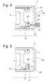
- the wall 35 in the variants of the 8 and 9 is made elastic by using a membrane.
- the elastic wall 35 is fixed to the piston, the only difference between the FIGS. 8 and 9 exists in the connection areas on the piston 5.
- the pressure in the working chamber 7 acts on the elastic wall and biases it in the direction of the piston, so that a permanent pressure is exerted on the lubricant reservoir, which can spread over the lubricant supply channel 31 in the direction of the contact surface 33.
- the lubricant reservoir 29 is formed by the piston 5 and an angle ring 57 on the piston 5.
- a throttle opening 59 is executed, which reduces the force acting on the movable wall 35 pressure from the working space 7 to a desired level.
- Fig. 14 is very similar to the post FIG. 11 , Notwithstanding, no biasing element 61 is used, but a movable wall 35 on a separating piston 37, the moment of inertia is used for pulsating promotion of the lubricant.
- the contact surface 33 is actively supplied with lubricant by means of external energy.
- a supply line 67 is available, which penetrates the bottom 23 of the cylinder 3 and extends into the housing formed by the angle ring 57, wherein a portion 69 between the angle ring and the bottom 23 is made variable in length.
- the separating piston 37 separates the lubricant reservoir 29 from a biasing space which is filled with a gas or liquid pressure medium via the supply line and thus ensures independent of the pressure in the working chamber 7 wetting the contact surface 33.
- the Fig. 16 shows a plunger 39 as a cylinder-side supporting actuator which is axially movably mounted in the bottom 23 of the cylinder 3 and the rear side can be acted upon by the supply line 67 by means of external energy with pressure medium to move the separating piston 37 on the lubricant reservoir 29 on.
- the lubricant is supplied via the supply line 67 via an outer region of the actuator directly to the contact region 33.
- the lubricant reservoir which is refilled via the supply line 67.
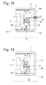
- An actuator 71 in the Fig. 18 gets job energy, z. As electrical power, supplied via the supply line 67 and is arranged on the piston-side housing or angle ring 57. The actuator 71 moves the separating piston 37 and biases the lubricant reservoir 29.
- a check valve 73 between the contact portion 33 and the lubricant reservoir 29 may be used, so that a return movement of the lubricant, for. B. due to the pressure in the working chamber 7, prevented in the lubricant supply chamber 29.
- FIG. 19 shows a the principle of Fig. 18 following actuator arrangement. Notwithstanding, the actuator 71 is not operated by means of external energy, but z. B. formed by a wax-thermo-element which exerts a temperature-dependent biasing force on the movable wall 35.
- the lubricant reservoir 29 is always within the working space 7, either on the piston 5 or on the cylinder 3.
- the solutions according to the FIGS. 20 to 22 show variants in which the lubricant reservoir 29 is disposed outside of the pressure medium filled working space 7.
- a relative to the actuating device, ie piston 5 and cylinder 3, exporting transmission element is utilized in the clutch actuation.
- the transmission element in the Fig. 20; 21 is formed by the bearing 13, the inner ring 15 as a relative movement to the actuator can perform a radial wobbling movement to the outer ring 17.
- the inner ring 13 acts by direct contact with the movable wall 35 and thus pumps lubricant from the lubricant reservoir 29 into the lubricant supply channel. 31.
- the difference between the FIGS. 20 and 21 is that the inner ring in Fig. 20 radial, in Fig. 21 axially presses on the wall 35.
- Fig. 22 is the lubricant reservoir 29 stationary fixed to the guide sleeve 11.
- the movable wall 35 is part of a separating piston 37, which is acted upon by the biasing spring 9 of the vehicle clutch.
Landscapes
- Engineering & Computer Science (AREA)
- General Engineering & Computer Science (AREA)
- Mechanical Engineering (AREA)
- Transmission Devices (AREA)
- Hydraulic Clutches, Magnetic Clutches, Fluid Clutches, And Fluid Joints (AREA)
Applications Claiming Priority (1)
| Application Number | Priority Date | Filing Date | Title |
|---|---|---|---|
| DE102007043971A DE102007043971A1 (de) | 2007-09-14 | 2007-09-14 | Betätigungseinrichtung |
Publications (2)
| Publication Number | Publication Date |
|---|---|
| EP2037145A2 true EP2037145A2 (fr) | 2009-03-18 |
| EP2037145A3 EP2037145A3 (fr) | 2009-07-08 |
Family
ID=40044010
Family Applications (1)
| Application Number | Title | Priority Date | Filing Date |
|---|---|---|---|
| EP08163361A Withdrawn EP2037145A3 (fr) | 2007-09-14 | 2008-09-01 | Dispositif d'actionnement |
Country Status (2)
| Country | Link |
|---|---|
| EP (1) | EP2037145A3 (fr) |
| DE (1) | DE102007043971A1 (fr) |
Cited By (2)
| Publication number | Priority date | Publication date | Assignee | Title |
|---|---|---|---|---|
| WO2011072641A3 (fr) * | 2009-12-17 | 2011-08-04 | Schaeffler Technologies Gmbh & Co. Kg | Maître-cylindre |
| CN121079512A (zh) * | 2023-05-25 | 2025-12-05 | Thk株式会社 | 滚动引导装置 |
Families Citing this family (1)
| Publication number | Priority date | Publication date | Assignee | Title |
|---|---|---|---|---|
| DE102009034790B4 (de) * | 2009-07-25 | 2024-02-01 | Aventics Gmbh | Zylinder mit Endlagendämpfung |
Citations (2)
| Publication number | Priority date | Publication date | Assignee | Title |
|---|---|---|---|---|
| DE19811657A1 (de) | 1998-03-18 | 1999-09-23 | Schaeffler Waelzlager Ohg | Hydraulisch betätigbares Ausrücksystem |
| DE10323953A1 (de) | 2003-05-27 | 2004-12-16 | Zf Sachs Ag | Betätigungseinrichtung für eine Fahrzeugkupplung |
Family Cites Families (12)
| Publication number | Priority date | Publication date | Assignee | Title |
|---|---|---|---|---|
| US1768633A (en) * | 1929-06-03 | 1930-07-01 | Henry C Ries | Piston for oil-well circulation pumps |
| FR1075910A (fr) * | 1952-04-21 | 1954-10-21 | Cav Ltd | Mécanisme à mouvement alternatif |
| GB986585A (en) * | 1962-04-19 | 1965-03-17 | David Theodore Nelson Williams | Improvements in or relating to hydraulic systems |
| DE1475871A1 (de) * | 1965-10-30 | 1969-01-30 | Teves Gmbh Alfred | Kolben fuer Nehmerzylinder von hydraulischen Anlagen |
| DE2631382C3 (de) * | 1976-07-13 | 1982-02-18 | Festo-Maschinenfabrik Gottlieb Stoll, 7300 Esslingen | Kolben, insbesondere für einen Pneumatikzylinder |
| US4157057A (en) * | 1976-11-18 | 1979-06-05 | Reed Tool Company | Single acting piston |
| DE2919486A1 (de) * | 1979-05-15 | 1980-12-04 | Bosch Gmbh Robert | Nachschmiereinrichtung fuer elektrische maschinen |
| DE3713248A1 (de) * | 1987-04-18 | 1988-11-03 | Boge Ag | Zylinder fuer hydraulische anlagen |
| DE10163278A1 (de) * | 2001-12-21 | 2003-07-10 | Wacker Construction Equipment | Bohr- und/oder Schlaghammer mit einer Schmiervorrichtung |
| DE10229746A1 (de) * | 2002-07-03 | 2004-01-15 | Zf Sachs Ag | Ausrücker mit einem automatisch nachgeschmierten Ausrücklager |
| DE10314962A1 (de) * | 2003-04-02 | 2004-10-28 | Zf Sachs Ag | Dichtung für eine Betätigungseinrichtung |
| US6959913B2 (en) * | 2003-06-13 | 2005-11-01 | Dynamic Air Inc. | Actuator |
-
2007
- 2007-09-14 DE DE102007043971A patent/DE102007043971A1/de not_active Ceased
-
2008
- 2008-09-01 EP EP08163361A patent/EP2037145A3/fr not_active Withdrawn
Patent Citations (2)
| Publication number | Priority date | Publication date | Assignee | Title |
|---|---|---|---|---|
| DE19811657A1 (de) | 1998-03-18 | 1999-09-23 | Schaeffler Waelzlager Ohg | Hydraulisch betätigbares Ausrücksystem |
| DE10323953A1 (de) | 2003-05-27 | 2004-12-16 | Zf Sachs Ag | Betätigungseinrichtung für eine Fahrzeugkupplung |
Cited By (2)
| Publication number | Priority date | Publication date | Assignee | Title |
|---|---|---|---|---|
| WO2011072641A3 (fr) * | 2009-12-17 | 2011-08-04 | Schaeffler Technologies Gmbh & Co. Kg | Maître-cylindre |
| CN121079512A (zh) * | 2023-05-25 | 2025-12-05 | Thk株式会社 | 滚动引导装置 |
Also Published As
| Publication number | Publication date |
|---|---|
| EP2037145A3 (fr) | 2009-07-08 |
| DE102007043971A1 (de) | 2009-05-20 |
Similar Documents
| Publication | Publication Date | Title |
|---|---|---|
| DE102007063360B4 (de) | Hydraulikanordnung für eine kraftbetätigte Stelleinheit | |
| EP2079923A1 (fr) | Pompe à piston, notamment pompe de carburant haute pression, avec poussoir à galet | |
| DE102013200410B4 (de) | Gaspumpe mit Druckentlastung zur Reduzierung des Anfahrdrehmoments | |
| EP3938695A1 (fr) | Distributeur de lubrifiant | |
| EP2126391B1 (fr) | Embrayage multidisques à pression de ressort pour compresseurs | |
| DE102007034036A1 (de) | Kraftstoffhochdruckpumpe mit Rollenstößel | |
| EP0772740A1 (fr) | Pompe a piston | |
| EP2037145A2 (fr) | Dispositif d'actionnement | |
| DE102011055871A1 (de) | Kraftstoffversorgungspumpe und Verfahren zur Herstellung eines Gehäuses für diese | |
| EP1158181A2 (fr) | Vérin électrohydraulique | |
| DE102016000707A1 (de) | Vorrichtung zur Betätigung einer Kupplung | |
| DE202019102210U1 (de) | Hydraulischer doppeltwirkender Stellantrieb | |
| EP1929154B1 (fr) | Pompe a piston | |
| WO2007144228A1 (fr) | Pompe à piston pour une installation de frein de véhicule | |
| EP2342118B1 (fr) | Direction assistée hydraulique | |
| WO2015176988A1 (fr) | Machine à pistons axiaux | |
| DE10321288A1 (de) | Hydraulisches System | |
| DE102013217237A1 (de) | Kombinierte Fahrzeugbremse mit elektromechanischer Feststellbremsbetätigung | |
| DE102006052775A1 (de) | Kolbenpumpe | |
| DE102013222397B4 (de) | Exzenterantrieb eines Hydraulikaggregats einer Fahrzeugbremsanlage mit einem Gleitlager, das einen exzentrischen Innenring aufweist, dessen Innenringstirnseiten von einem Außenring teilweise umgriffen sind | |
| DE102009003097B4 (de) | Hochdruckpumpe, insbesondere Radialkolbenpumpe, mit zumindest einem Stößelkörper, einem verdrehbaren Rollenschuh, einer Laufrolle und einer axialen Anlagestelle für die Laufrolle, die beabstandet zur Drehachse der Laufrolle angeordnet ist | |
| DE19949525A1 (de) | Druckübersetzer für ein Kraftstoffeinspritzsystem für Brennkraftmaschinen mit hydraulisch unterstützter Wiederbefüllung | |
| DE102008041305A1 (de) | Hydraulikversorgungseinheit | |
| EP1659308B1 (fr) | Dispositif d'embrayage pour l'accouplement d'un dispositif auxiliiaire | |
| DE102017218730A1 (de) | Kraftstoffhochdruckpumpe |
Legal Events
| Date | Code | Title | Description |
|---|---|---|---|
| PUAI | Public reference made under article 153(3) epc to a published international application that has entered the european phase |
Free format text: ORIGINAL CODE: 0009012 |
|
| AK | Designated contracting states |
Kind code of ref document: A2 Designated state(s): AT BE BG CH CY CZ DE DK EE ES FI FR GB GR HR HU IE IS IT LI LT LU LV MC MT NL NO PL PT RO SE SI SK TR |
|
| AX | Request for extension of the european patent |
Extension state: AL BA MK RS |
|
| PUAL | Search report despatched |
Free format text: ORIGINAL CODE: 0009013 |
|
| AK | Designated contracting states |
Kind code of ref document: A3 Designated state(s): AT BE BG CH CY CZ DE DK EE ES FI FR GB GR HR HU IE IS IT LI LT LU LV MC MT NL NO PL PT RO SE SI SK TR |
|
| AX | Request for extension of the european patent |
Extension state: AL BA MK RS |
|
| 17P | Request for examination filed |
Effective date: 20091201 |
|
| 17Q | First examination report despatched |
Effective date: 20100105 |
|
| AKX | Designation fees paid |
Designated state(s): AT BE BG CH CY CZ DE DK EE ES FI FR GB GR HR HU IE IS IT LI LT LU LV MC MT NL NO PL PT RO SE SI SK TR |
|
| STAA | Information on the status of an ep patent application or granted ep patent |
Free format text: STATUS: THE APPLICATION HAS BEEN WITHDRAWN |
|
| 18W | Application withdrawn |
Effective date: 20100420 |