EP2037166A2 - Capot de machine doté d'un capot de protection à longueur réglable - Google Patents
Capot de machine doté d'un capot de protection à longueur réglable Download PDFInfo
- Publication number
- EP2037166A2 EP2037166A2 EP08015810A EP08015810A EP2037166A2 EP 2037166 A2 EP2037166 A2 EP 2037166A2 EP 08015810 A EP08015810 A EP 08015810A EP 08015810 A EP08015810 A EP 08015810A EP 2037166 A2 EP2037166 A2 EP 2037166A2
- Authority
- EP
- European Patent Office
- Prior art keywords
- movable
- coupling member
- terminal member
- stationary
- machine
- Prior art date
- Legal status (The legal status is an assumption and is not a legal conclusion. Google has not performed a legal analysis and makes no representation as to the accuracy of the status listed.)
- Withdrawn
Links
Images


Classifications
-
- F—MECHANICAL ENGINEERING; LIGHTING; HEATING; WEAPONS; BLASTING
- F16—ENGINEERING ELEMENTS AND UNITS; GENERAL MEASURES FOR PRODUCING AND MAINTAINING EFFECTIVE FUNCTIONING OF MACHINES OR INSTALLATIONS; THERMAL INSULATION IN GENERAL
- F16P—SAFETY DEVICES IN GENERAL; SAFETY DEVICES FOR PRESSES
- F16P3/00—Safety devices acting in conjunction with the control or operation of a machine; Control arrangements requiring the simultaneous use of two or more parts of the body
- F16P3/02—Screens or other safety members moving in synchronism with members which move to and fro
Definitions
- Such machine covers are often designed as if necessary from above accessible roofing. In the normal operating state, these close the working space upwards. For example, from above for crane loading of large and heavy workpieces, it is necessary to form the protective or roof covers releasably and displaceably. In this context, it is known, for example, to release appropriate screw connections or bolt locks by hand to open and then to move the protective cover opening by hand, and then to undo these operations to close again.
- These processes are partly also by a controlled opening and closing by electrical, pneumatic or hydraulic.
- consoles end frames with their own drive. All of these solutions are complicated and expensive. They either require expensive electrical, pneumatic or hydraulic additional parts, special manufacturer-specific interfaces or manual intervention.
- the present invention has for its object to provide a machine cover of the type mentioned in such a way that it can be easily and quickly opened and closed again in a simple mechanical way without manual intervention with cost-effective means purely mechanical way.
- the invention proposes that the end of the protective cover stationary in the working area is firmly connected to a double-sided reversible coupling member which has a releasable mechanical connection to the stationary connecting member in the working area of the protective cover.
- Such a machine cover is simple, reliable and inexpensive, requires no manual intervention for unlocking and locking and works with integrated parts purely mechanically without external drives. It uses the available on each machine in each machine axis and machine side controllable overstroke, in which the variable-length protective cover beyond their normal work area going further can be shortened a little further into a normally unused Kochhub Symposium. There, the corresponding unlocking and locking operations between the coupling member and the stationary terminal member and the movable terminal member carried by simple mechanical movement pressure operations.
- the mechanical pressure cans in the overstroke range simultaneously or according to claim 5 respond successively.
- the pressure cell for the releasable mechanical connection of the coupling member to the movable terminal member respond to those for the releasable mechanical connection of the coupling member with the stationary terminal member.
- the further embodiment according to claim 8 is in the overstroke - ie outside the normal working area - ensure an accurate motion control of the movable connecting member relative to the coupling member and a stop-related entrainment of the coupling member.
- Fig. 1 is a variable-length protective cover 10 of any kind - such as a bellows, a roll cover with steel or plastic tape, a slat cover, a link skirt, a telescopic steel cover o. The like.
- a variable-length protective cover 10 of any kind - such as a bellows, a roll cover with steel or plastic tape, a slat cover, a link skirt, a telescopic steel cover o. The like.
- - At one end with a movable terminal member 14 and at the other end with a coupling member 26 fixedly connected ,
- the movable connecting member 14 on the machine side linear reciprocating driven, while the coupling member 26 is releasably connected in this work area 16 with a machine-connected stationary terminal member 12.
- the protective cover 10 can be shortened in accordance with an abbreviated shortening in its operative working area 16 and pulled apart in a prolonged manner.
- the terminal member 14 can move with its parts connected between a minimum operating position 18 with the strongest shortening of the protective cover 10 and a maximum operating position 20 with the greatest possible extension of the protective cover 10.
- the operating minimum position 18 is adjoined by an overstroke region 22 with a maximum overstroke position 24.
- the Studentshub Society 22 is outside the normal operating or working state, if necessary, the machine side controlled to the Protective cover 10, for example, from above for crane loading of large and heavy workpieces according to Fig. 6 to open and later again according to Fig. 1 close.
- the coupling member 26 When opening operation, the coupling member 26 is mechanically separated at length shortened Schutzabdekkung 10 from the stationary terminal member 12 and mechanically connected to the movable terminal member 14. In this opening state, the movable terminal member 14, the coupling member 26 with the shortened protective cover 10 retreat, so that between the coupling member 26 and the stationary terminal member 12 according to Fig. 6 a space for corresponding crane loads o. The like. arises. Conversely, in the subsequent closing operation, the coupling member 26 from the movable terminal member 14 - the free space closes - moves to the stationary terminal member 12 and thereby mechanically separated from the movable terminal member 14 and mechanically connected to the stationary terminal member 12. As a result, the normal operating or working state is restored.
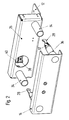
- the movable connecting member 14 with at least one movement stop 36 in the overstroke 22 is retractable. Upon reaching or within the same, the movement stop 36 abuts against the end face of a guide sleeve 34 on the coupling member 26. Previously, a guide cone 32 with a front-side connecting hook 28 on the movable connecting member 14 has penetrated into the guide sleeve 34. At the coupling member 26 is at least one of the FIGS. 1 .
- reversibly releasable mechanical pressure box 30 is mounted, in which the connecting hooks 28 of the movable connection member 14 releasably latching inserted to the first through this mechanical pressure contact the connection hook 28 in the pressure box 30th locking anchoring.
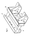
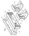
- the movement stop 36 presses in the overstroke region 22 via the guide sleeve 34, the coupling member 26 from the position in Fig. 3 further in the direction of the stationary terminal member 12 in the position in Fig. 4 ,
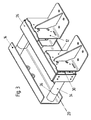
- At the stationary terminal member 12 is according to the Fig. 1 and 2 at least one also commercially available, reversibly releasable mechanical pressure box 40 attached, in this case one from the Fig. 2 and 6 apparent, already releasably anchored connection hook 38 on the coupling member 26 is further inserted.
- the movable connecting member 14 is moved again in the overstroke region 22.
- the anchored in the pressure cell 30 connecting hook 28 is released by re-pushing it into the pressure cell 30 of this unlocking.
- the connecting hook 38 in the pressure box 40 is a lock with this.
- the coupling member 26 is now again connected to the stationary terminal member 12 and released from the movable terminal member 14. Now, when moving back the movable connecting member 14 from the overstroke 22, the Schutzabdekkung 10 are operated again variable in length.
- two pressure cans 30 and 40 are present to achieve a uniform operation, each of which two connecting hooks 28 and 38 are assigned.
- more than two pressure sockets may be present, especially with very large machine covers.
- the arrangement of the pressure cans 30 and 40 on the coupling member 26 and on the stationary member 12 is not mandatory and can be changed for one or both pressure cans. Then also other arrangements of the connecting hooks 28, 38 would be provided accordingly.
- a combined double-sided, reversibly releasable mechanical pressure box could be attached to the coupling member 26, the corresponding connecting hooks 28 and 38 are assigned to the movable and stationary connection members 14 and 12.
Landscapes
- Engineering & Computer Science (AREA)
- General Engineering & Computer Science (AREA)
- Mechanical Engineering (AREA)
- Soil Working Implements (AREA)
- Pressure Vessels And Lids Thereof (AREA)
- Connection Of Plates (AREA)
Applications Claiming Priority (1)
| Application Number | Priority Date | Filing Date | Title |
|---|---|---|---|
| DE102007043808A DE102007043808A1 (de) | 2007-09-13 | 2007-09-13 | Maschinenabdeckung mit einer längenveränderlichen Schutzabdeckung |
Publications (2)
| Publication Number | Publication Date |
|---|---|
| EP2037166A2 true EP2037166A2 (fr) | 2009-03-18 |
| EP2037166A3 EP2037166A3 (fr) | 2009-12-23 |
Family
ID=40097173
Family Applications (1)
| Application Number | Title | Priority Date | Filing Date |
|---|---|---|---|
| EP08015810A Withdrawn EP2037166A3 (fr) | 2007-09-13 | 2008-09-09 | Capot de machine doté d'un capot de protection à longueur réglable |
Country Status (2)
| Country | Link |
|---|---|
| EP (1) | EP2037166A3 (fr) |
| DE (1) | DE102007043808A1 (fr) |
Cited By (1)
| Publication number | Priority date | Publication date | Assignee | Title |
|---|---|---|---|---|
| EP2907618A1 (fr) * | 2014-02-17 | 2015-08-19 | Arno Arnold GmbH | Recouvrement de machine |
Families Citing this family (5)
| Publication number | Priority date | Publication date | Assignee | Title |
|---|---|---|---|---|
| DE102009060097B4 (de) | 2009-12-21 | 2013-07-18 | Möller Werke GmbH | Abdeckungsvorrichtung |
| DE202014007338U1 (de) | 2014-09-15 | 2014-10-07 | Möller Werke GmbH | Maschinenschutzabdeckung |
| DE202019105099U1 (de) | 2019-09-13 | 2021-01-15 | Möller Werke GmbH | Abdeckvorrichtung für eine Maschinenkabine |
| DE202020102152U1 (de) | 2020-04-17 | 2021-07-20 | Möller Werke GmbH | Schutzabdeckungssystem |
| DE102020112377B4 (de) | 2020-05-07 | 2022-07-07 | Arno Arnold Gmbh | Schutzabdeckung mit Verriegelungseinrichtung zur Abdeckung von beweglichen Maschinenteilen |
Family Cites Families (6)
| Publication number | Priority date | Publication date | Assignee | Title |
|---|---|---|---|---|
| DE2505545A1 (de) * | 1975-02-10 | 1976-08-19 | Keil Heinz Toni | Unfallschutzplatte fuer arbeitsmaschinen, insbesondere bearbeitungs- und werkzeugmaschinen |
| DE4026609C1 (en) * | 1989-09-02 | 1991-05-02 | Hcr-Heinrich Cremer Gmbh, 4050 Moenchengladbach, De | Casing for guide track telescopic covers - has each side wall with longitudinal slit on edge adjacent to front wall |
| DE4117699A1 (de) * | 1991-05-30 | 1992-12-03 | Stama Maschinenfabrik Gmbh | Werkzeugmaschine mit feststehendem arbeitstisch und vertikaler arbeitsspindel |
| DE4436944C2 (de) * | 1994-10-15 | 1997-06-12 | Saechsische Werkzeug Und Sonde | Maschinentischabdeckung |
| DE29610893U1 (de) * | 1996-06-21 | 1996-08-14 | Kubitschek, Hans-Jörg, 57413 Finnentrop | Verschiebbarer Rollokasten zur Abdeckung von Maschinen |
| DE20200701U1 (de) * | 2002-01-18 | 2002-05-02 | HEMA Maschinen- und Apparateschutz GmbH, 63500 Seligenstadt | Stabilisierungsschere für eine Schutzabdeckung |
-
2007
- 2007-09-13 DE DE102007043808A patent/DE102007043808A1/de not_active Withdrawn
-
2008
- 2008-09-09 EP EP08015810A patent/EP2037166A3/fr not_active Withdrawn
Cited By (1)
| Publication number | Priority date | Publication date | Assignee | Title |
|---|---|---|---|---|
| EP2907618A1 (fr) * | 2014-02-17 | 2015-08-19 | Arno Arnold GmbH | Recouvrement de machine |
Also Published As
| Publication number | Publication date |
|---|---|
| DE102007043808A1 (de) | 2009-03-19 |
| EP2037166A3 (fr) | 2009-12-23 |
Similar Documents
| Publication | Publication Date | Title |
|---|---|---|
| AT403040B (de) | Teleskopierstab | |
| CH680522A5 (fr) | ||
| DE69505203T2 (de) | Hydraulischer Kreislauf | |
| EP2037166A2 (fr) | Capot de machine doté d'un capot de protection à longueur réglable | |
| DE202008007903U1 (de) | Verriegelungsvorrichtung mit Zylinderbetätigung zur Seite | |
| EP1484275B1 (fr) | Unité de verrouillage et d'actionnement pour un dispositif de verrouillage latéral d'une flèche | |
| DE19653502C2 (de) | Vorrichtung zum Arretieren bzw. Lösen der Arretierung von Schüssen eines Teleskopauslegers für einen fahrbaren Kran | |
| EP0274710A1 (fr) | Pince motorisée portable pour le serrage de cavaliers ou similaires | |
| WO2018204951A1 (fr) | Rail de guidage d'un chariot d'une porte de meuble | |
| DE10048224B4 (de) | Verriegelungseinheit für einen Teleskopausleger eines Krans | |
| EP4048122B1 (fr) | Combinaison d'un element de mouvement et d'un element de synchronisation pour des rails de tiroir | |
| EP0941889A2 (fr) | Dispositif d'extraction | |
| DE2619031C2 (fr) | ||
| DE102011116083B4 (de) | Sicherungs- und Verriegelungseinheit für Ausleger mit teleskopierbaren Schüssen, insbesondere bei Mobilkranen | |
| DE3020788C2 (de) | Innenverschlußeinrichtung für einen Weichenantrieb | |
| EP2907618A1 (fr) | Recouvrement de machine | |
| EP2733286B1 (fr) | Fermeture à levier pivotant ayant une faible profondeur d'intégration | |
| DE10004838B4 (de) | Kran mit einem Teleskopausleger | |
| DE102012002122B4 (de) | Verriegelungsvorrichtung für einen Teleskopausleger | |
| WO2009095032A1 (fr) | Interrupteur de sécurité à fonction de verrouillage pour l'ouverture forcée d'éléments de contact et procédé d'ouverture forcée d'éléments de contact d'un interrupteur de sécurité à fonction de verrouillage | |
| DE202008007902U1 (de) | Verriegelungsvorrichtung mit Rotorbetätigung nach unten | |
| EP0460475A1 (fr) | Flèche télescopique avec dispositif d'accouplement pour mécanisme d'extension | |
| DE20120964U1 (de) | Abstützvorrichtung für Baumaschinen wie Hydraulikbagger u.dgl. | |
| DE19908191C1 (de) | Automatische Flügel- oder Türanlage | |
| DE102011015086B3 (de) | Antriebsvorrichtung |
Legal Events
| Date | Code | Title | Description |
|---|---|---|---|
| PUAI | Public reference made under article 153(3) epc to a published international application that has entered the european phase |
Free format text: ORIGINAL CODE: 0009012 |
|
| AK | Designated contracting states |
Kind code of ref document: A2 Designated state(s): AT BE BG CH CY CZ DE DK EE ES FI FR GB GR HR HU IE IS IT LI LT LU LV MC MT NL NO PL PT RO SE SI SK TR |
|
| AX | Request for extension of the european patent |
Extension state: AL BA MK RS |
|
| PUAL | Search report despatched |
Free format text: ORIGINAL CODE: 0009013 |
|
| AK | Designated contracting states |
Kind code of ref document: A3 Designated state(s): AT BE BG CH CY CZ DE DK EE ES FI FR GB GR HR HU IE IS IT LI LT LU LV MC MT NL NO PL PT RO SE SI SK TR |
|
| AX | Request for extension of the european patent |
Extension state: AL BA MK RS |
|
| AKX | Designation fees paid |
Designated state(s): AT BE BG CH CY CZ DE DK EE ES FI FR GB GR HR HU IE IS IT LI LT LU LV MC MT NL NO PL PT RO SE SI SK TR |
|
| STAA | Information on the status of an ep patent application or granted ep patent |
Free format text: STATUS: THE APPLICATION IS DEEMED TO BE WITHDRAWN |
|
| 18D | Application deemed to be withdrawn |
Effective date: 20100624 |