EP2037176B1 - Procédé de commande d'un brûleur à évaporation - Google Patents
Procédé de commande d'un brûleur à évaporation Download PDFInfo
- Publication number
- EP2037176B1 EP2037176B1 EP08105288.8A EP08105288A EP2037176B1 EP 2037176 B1 EP2037176 B1 EP 2037176B1 EP 08105288 A EP08105288 A EP 08105288A EP 2037176 B1 EP2037176 B1 EP 2037176B1
- Authority
- EP
- European Patent Office
- Prior art keywords
- correction factor
- heating power
- evaporator
- int
- temperature
- Prior art date
- Legal status (The legal status is an assumption and is not a legal conclusion. Google has not performed a legal analysis and makes no representation as to the accuracy of the status listed.)
- Not-in-force
Links
- 238000000034 method Methods 0.000 title claims description 22
- 238000009834 vaporization Methods 0.000 title description 2
- 238000012937 correction Methods 0.000 claims description 47
- 238000010438 heat treatment Methods 0.000 claims description 44
- 239000000446 fuel Substances 0.000 claims description 37
- 230000008569 process Effects 0.000 claims description 10
- 238000002485 combustion reaction Methods 0.000 claims description 9
- 230000001419 dependent effect Effects 0.000 claims description 7
- 239000000203 mixture Substances 0.000 claims description 2
- 101150038956 cup-4 gene Proteins 0.000 description 11
- 230000008859 change Effects 0.000 description 7
- 239000007788 liquid Substances 0.000 description 3
- 238000005259 measurement Methods 0.000 description 3
- 210000002023 somite Anatomy 0.000 description 3
- 238000004364 calculation method Methods 0.000 description 2
- 239000000567 combustion gas Substances 0.000 description 2
- 238000010586 diagram Methods 0.000 description 2
- 230000036962 time dependent Effects 0.000 description 2
- XLYOFNOQVPJJNP-UHFFFAOYSA-N water Substances O XLYOFNOQVPJJNP-UHFFFAOYSA-N 0.000 description 2
- 230000009471 action Effects 0.000 description 1
- 230000032683 aging Effects 0.000 description 1
- 230000008901 benefit Effects 0.000 description 1
- 238000011109 contamination Methods 0.000 description 1
- 230000008021 deposition Effects 0.000 description 1
- 238000011161 development Methods 0.000 description 1
- 230000018109 developmental process Effects 0.000 description 1
- 230000000694 effects Effects 0.000 description 1
- 230000007613 environmental effect Effects 0.000 description 1
- 230000008020 evaporation Effects 0.000 description 1
- 238000001704 evaporation Methods 0.000 description 1
- 238000002474 experimental method Methods 0.000 description 1
- 239000000295 fuel oil Substances 0.000 description 1
- 238000009434 installation Methods 0.000 description 1
- 239000003350 kerosene Substances 0.000 description 1
- 238000012886 linear function Methods 0.000 description 1
- 239000003921 oil Substances 0.000 description 1
- 230000000717 retained effect Effects 0.000 description 1
- 230000000630 rising effect Effects 0.000 description 1
- 230000035945 sensitivity Effects 0.000 description 1
- 230000008016 vaporization Effects 0.000 description 1
Images


Classifications
-
- F—MECHANICAL ENGINEERING; LIGHTING; HEATING; WEAPONS; BLASTING
- F23—COMBUSTION APPARATUS; COMBUSTION PROCESSES
- F23N—REGULATING OR CONTROLLING COMBUSTION
- F23N5/00—Systems for controlling combustion
- F23N5/02—Systems for controlling combustion using devices responsive to thermal changes or to thermal expansion of a medium
- F23N5/12—Systems for controlling combustion using devices responsive to thermal changes or to thermal expansion of a medium using ionisation-sensitive elements, i.e. flame rods
- F23N5/123—Systems for controlling combustion using devices responsive to thermal changes or to thermal expansion of a medium using ionisation-sensitive elements, i.e. flame rods using electronic means
-
- F—MECHANICAL ENGINEERING; LIGHTING; HEATING; WEAPONS; BLASTING
- F23—COMBUSTION APPARATUS; COMBUSTION PROCESSES
- F23N—REGULATING OR CONTROLLING COMBUSTION
- F23N1/00—Regulating fuel supply
- F23N1/02—Regulating fuel supply conjointly with air supply
- F23N1/022—Regulating fuel supply conjointly with air supply using electronic means
-
- F—MECHANICAL ENGINEERING; LIGHTING; HEATING; WEAPONS; BLASTING
- F23—COMBUSTION APPARATUS; COMBUSTION PROCESSES
- F23N—REGULATING OR CONTROLLING COMBUSTION
- F23N2223/00—Signal processing; Details thereof
- F23N2223/42—Function generator
-
- F—MECHANICAL ENGINEERING; LIGHTING; HEATING; WEAPONS; BLASTING
- F23—COMBUSTION APPARATUS; COMBUSTION PROCESSES
- F23N—REGULATING OR CONTROLLING COMBUSTION
- F23N2225/00—Measuring
- F23N2225/08—Measuring temperature
- F23N2225/16—Measuring temperature burner temperature
-
- F—MECHANICAL ENGINEERING; LIGHTING; HEATING; WEAPONS; BLASTING
- F23—COMBUSTION APPARATUS; COMBUSTION PROCESSES
- F23N—REGULATING OR CONTROLLING COMBUSTION
- F23N2233/00—Ventilators
- F23N2233/06—Ventilators at the air intake
- F23N2233/08—Ventilators at the air intake with variable speed
-
- F—MECHANICAL ENGINEERING; LIGHTING; HEATING; WEAPONS; BLASTING
- F23—COMBUSTION APPARATUS; COMBUSTION PROCESSES
- F23N—REGULATING OR CONTROLLING COMBUSTION
- F23N2235/00—Valves, nozzles or pumps
- F23N2235/30—Pumps
Definitions
- the invention relates to a method for controlling an evaporator burner of the type mentioned in the preamble of claim 1.
- Such an evaporator burner is designed for the combustion of liquid fuels such as commercial heating oil of various qualities or kerosene and is particularly suitable for heating systems of residential buildings, but also of non-residential buildings, where a rather low heating power in the range of a few kilowatts is sufficient.
- the heat generated by the burner when burning the fuel for example, heats water in a boiler.
- the liquid fuel is vaporized under heat, mixed with air and then burned.
- An evaporator burner referred to in the preamble of claim 1 is known from the WO 00/12935 known.
- the evaporator burner is located below the boiler.
- the evaporator chamber is electrically preheated at the start of the burner. As soon as the flame burns, the evaporator chamber is then heated by the hot combustion gases flowing past the evaporator chamber, which is achieved by means of a deflecting collar. Once the evaporator chamber has reached a predetermined temperature, which is monitored by means of a temperature sensor, the electric heater can be turned off.
- This evaporator burner is designed as a tumble burner and is mounted on top of the boiler. The flame burns below the evaporator chamber. The rising hot combustion gases heat the evaporator chamber directly.
- evaporator burners are designed as modulating burners, i. Their heating power can be steplessly controlled in a predetermined work area.
- the evaporation of the fuel is extremely important. So the temperature of the evaporator chamber must be high enough for the fuel to evaporate completely.
- the amount of air supplied must be adapted to the amount of fuel supplied. If more air is supplied than is needed for the combustion, then this reduces the efficiency. If less air is supplied than is needed for the combustion, then this increases on the one hand the exhaust emissions and on the other hand leads to the deposition of unburned or not completely burned fuel residues.
- the invention has for its object to develop a method for the optimal operation of such an evaporator burner, without measuring devices for measuring the amount of air supplied and the supplied amount of fuel manages.
- the Fig. 1 shows a vertical section through the necessary for the understanding of the invention parts of such designed as a tumble burner evaporator burner.
- the evaporator burner comprises an evaporator chamber 1, a blower 2, an electric motor 3 for driving the blower 2, an atomizer cup 4, a mixing wheel 5 and a flame holder 6.
- the flame burns on the outer wall of the flame holder 6.
- the blower 2 comprises two rotors 8 and 9, which are mounted on a drive shaft 7 driven by the motor 3.
- the rotors 8, 9 convey fresh air into the evaporator chamber 1.
- the flame holder 6 contains a lid and rests on the evaporator chamber 1.
- the evaporator chamber 1 is a chamber open to the flame holder 6 with a bottom 10 and a side wall 11. The space enclosed by the bottom 10 and the side wall 11 of the evaporator chamber 1 space forms a mixing and evaporator zone.
- an electric heater 12 is integrated in the wall of the evaporator chamber 1, in the wall of the evaporator chamber 1, an electric heater 12 is integrated.
- the atomizer cup 4 and the mixing wheel 5 are also mounted on the drive shaft 7 in this embodiment, ie the atomizer cup 4, the mixing wheel 5 and the rotors 8, 9 of the fan 2 rotate together at the same speed.
- the atomizer cup 4 and the mixing wheel 5 could also be driven separately.
- a fuel pump 13 delivers liquid fuel through a fuel line 14, which projects into the atomizer cup 4.
- the pumped fuel flows or drips onto the inner wall of the atomizer cup 4. Due to the rotation of the atomizer cup 4, the fuel flows against the outer edge of the atomizer cup 4 under the action of centrifugal force, is thrown off the edge and impinges on the inner wall of the evaporator chamber 1. Simultaneously 2 fresh air is conveyed by the rotors 8, 9 of the blower.
- a certain proportion of the fresh air flows outside the atomizer cup 4 along directly into the evaporator chamber 1, another portion of the fresh air passes through openings in the bottom of the Atomizer cup 4 into the interior of the atomizer cup 4 and the mixing wheel 5.
- the rotating mixing wheel 5 serves to redirect the supplied fresh air into the evaporator chamber 1, to swirl and to mix with the evaporated fuel oil vapor.
- Such an evaporator burner can be designed as a tumble burner as shown, but it can also be designed for any other installation position, for example, a horizontal mounting position. It is suitable for use with condensing boilers as well as boilers of other types.
- the evaporator burner is a modulatable burner, in which the heating power P between a low load value P min and a nominal load value P max can be varied continuously or in stages.
- the low load value P min is typically about 30 to 35% of the rated load value P max .
- the evaporator burner is mounted on a boiler whose water temperature is controlled by a heating controller.
- the heating controller requires from the evaporator burner a heating power P which is in the range between P min + k * (P max -P min ), wherein the size k denotes the degree of modulation of the evaporator burner and assumes values between 0 and 1.
- the requested heating power P changes continuously according to the current heat demand.
- the commissioning of the burner comprises in a known manner the switching on of the electric heater 12 of the evaporator chamber 1. As a result, the temperature of the evaporator chamber 1 increases. Once the temperature of the evaporator chamber 1 has reached a predetermined value, the combustion chamber is vented, then adjusted the speed of the fan 2 of the set ignition power and finally started the fuel supply to the burner. On the outer wall of the flame holder 6 is then formed by an ignition, the flame. As a result, now the evaporator chamber 1 is further heated by the heat developed by the flame, so that the temperature of the evaporator chamber 1 further increases. Once the temperature of the evaporator chamber 1 has reached a predetermined value, the electric heater 12 of the evaporator chamber 1 is turned off.
- the function g (P) is a function indicating at which speed the fan 2 must rotate, when the burner has to supply the heating power P. It is set so that the temperature of the evaporator chamber 1 under ideal operating conditions and without application of the correction factor K (P) at the heating power P min reaches a predetermined value T VDKmin increases linearly with increasing heating power and at the maximum heating power P max a predetermined value T VDKmax reached.
- a function g (P) has proven itself, which, as in the Fig. 2 is shown by two straight lines G 1 and G 2 with different pitch can be displayed.
- the setpoint T S (P) is a function dependent only on the heating power P.
- the Fig. 3 shows the dependence of the setpoint T S of the heating power P and the modulation depth k for a developed by the applicant evaporator burner.
- the internal setpoint value T int (t) serves to simulate the effective behavior of the actual temperature of the evaporator chamber 1. It depends on the course of business. If the requested heating power P suddenly abruptly changes, then the setpoint T S (P) also changes abruptly, while the internal setpoint T int (t) is tracked to the setpoint T S via a power-dependent low-pass filter. Measurements have shown that the internal setpoint value T int (t) is advantageously tracked according to an e-function with a predetermined time constant adapted to the burner.
- T int t n + 1 T int t n + ⁇ * T S k t n + 1 - T int t n
- ⁇ is set so that the course of the internal target value T int simulates the course of the actual temperature of the evaporator chamber 1 as well as possible during a power change.
- the internal setpoint T int (t) is at a predetermined frequency f 1 of, for example, 0.1 Hz, ie every 10th Seconds, updated.
- the correction factor K (P) is a factor that serves to minimize deviations from the ideal air / fuel ratio.
- the causes of such deviations are manifold, on the one hand there are external factors such as the weather conditions (air pressure, humidity, etc.) and internal factors such as the degree of contamination of the evaporator chamber, etc.
- the correction factor K is therefore constantly updated during operation.
- the Fig. 4 shows the dependence of the correction factor K on the heating power P and the degree of modulation k.
- K 1 and K 2 denote two interpolation point values, namely K 1 a reference point value for low load and K 2 a reference point value for nominal load.
- the correction factor K should be increased by a value appropriate to the amount of the temperature difference ⁇ T. As a result, the rotational speed D of the blower 2 and thus the air supply is increased. If the temperature difference ⁇ T is less than 0, it means that the evaporator chamber 1 is too cold. Therefore, the correction factor K should be reduced by a value appropriate to the amount of the temperature difference ⁇ T.
- the change of the correction factor K can be made in various ways.
- a first possibility is to increase or decrease both interpolation point values K 1 and K 2 by an equal value ⁇ k ( ⁇ T), the function ⁇ k ( ⁇ T) being a predetermined function. Because disturbing changes in the environmental conditions (eg soiling of the boiler, etc.) on the Operation at low load and under heavy load have different effects, the correction values for low load and high load are advantageously tracked separately.
- a second, preferred option is therefore to change the two interpolation values by different values and this in function of the current heating power.
- the interpolation point value K 2 (t n + 1 ) is limited to values within the predetermined range B 1 ... B 2 . This ensures that the correction factor K is within the predetermined range B 1 ... B 2 .
- K P t n + 1 K 1 t n + 1 + k * K 2 t n + 1 - K 1 t n + 1
- the two interpolation points K 1 and K 2 are performed as time-dependent parameters like the internal reference value T int and recalculated periodically but with different frequencies.
- the update of the correction factor K can be omitted if the measured temperature difference .DELTA.T is less than a minimum temperature difference .DELTA.T min , make no sense below the corrections of the correction factor K, since the measurement accuracy of the temperature sensor 15 is only about 2.5 ° C.
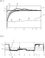
- the Fig. 8 shows in a diagram four curves 16 to 19.
- the curve 16 shows the course of the heating demand from the requested by the heating controller P (t) setpoint value T S (P (t)) for the temperature of the evaporator chamber 1 ( Fig. 1
- the curve 17 shows the profile of the internal setpoint value T int (t)
- the curve 18 shows the course of the actual temperature of the evaporator chamber 1 measured by the temperature sensor 15
- the curve 19 shows the course of the speed D (t) of the blower 2
- the time t is shown on the abscissa axis and the temperature on the ordinate axis T.
- the correction factor K (P) is updated every 15 minutes.
- Time t 0 0: The evaporator burner is turned on, with the heating power P max is requested for the ignition.
- the set point T S (P max ) is a constant value, as illustrated by the curve 16.
- the internal setpoint T int (t) increases continuously and reaches the setpoint T S (P max ) after about 20 minutes.
- the actual temperature (curve 18) rises faster than the internal setpoint T int (t) and overshoots.
- the Fig. 9 shows in a diagram the course of the three curves 16 to 18 during a later phase of operation, during which the heater controller requested by the heating power P changes over again.
- the course of the rotational speed D (t) of the blower 2 is not shown here.
- the update of the correction factor K is carried out according to predetermined criteria, preferably independently of the operating state of the burner periodically with the frequency f 2 , in the example in a clock of 15 minutes, as described above.
- the update can also occur when certain events occur or even aperiodic.
- the correction factor K (P) is continuously updated and stored as described. It is retained even if the evaporator burner is switched off. The next time the evaporator burner starts, the stored correction factor K (P) serves as the output value.
- the interpolation point values K 1 and K 2 are increased by a predetermined value, for example by 0.02.
- the correction factor K ie the interpolation point values K 1 and K 2 , is automatically reset to 0.
- the burner does not run stably, which manifests itself as considerable fluctuations in the heating power, it is advantageous to make no or a change in the correction factor K which is less than normal.
- the update of the correction factor K takes place in a fixed clock at predetermined times. If the variation of the heating power from the last time to the new time exceeds a predetermined value, then the correction factor K is not or only partially updated.
- the fuel pump 13 is, for example, an oscillating piston pump.
- the amount of fuel delivered is proportional to the operating frequency, the so-called metering F.
- the factor ⁇ will be checked if necessary and updated if necessary.
- the updating of the factor ⁇ is preferably carried out when the evaporator burner runs stable at low load P min , because at low load, the dependence of the mentioned process variables of the excess air least and the sensitivity of the mentioned process variables is greatest.
Landscapes
- Engineering & Computer Science (AREA)
- Chemical & Material Sciences (AREA)
- Combustion & Propulsion (AREA)
- Mechanical Engineering (AREA)
- General Engineering & Computer Science (AREA)
- Regulation And Control Of Combustion (AREA)
- Control Of Combustion (AREA)
Claims (7)
- Procédé pour contrôler un brûleur d'évaporateur dont la puissance de chauffage P peut être modulée entre une valeur minimale Pmin et une valeur nominale Pmax, dans lequel un régulateur de niveau supérieur demande une puissance de chauffage P, le brûleur d'évaporateur comportant une chambre d'évaporation (1), une pompe à carburant (13) pour transporter le carburant, un ventilateur (2) pour transporter l'air de combustion, dont la vitesse de rotation D est contrôlable, un bécher atomiseur (4), une roue mélangeuse (5) et un porte-flammes (6), dans lequel la chambre d'évaporation (1) est une chambre avec un fond (10) et une paroi latérale (11) qui est ouverte vers le porte-flammes (6), et dans lequel au cours du procédé, au moyen de la pompe à carburant (13), une quantité de carburant correspondant à la puissance de chauffage P actuellement requise est introduite dans le bécher atomiseur (4) et la vitesse de rotation D du ventilateur (2) est contrôlée, caractérisé en ce que- la vitesse de rotation D du ventilateur (2) est contrôlée selon une fonction D = g (P) * (1 + K), où g (P) est une fonction dépendant de la puissance de chauffage P et K est un facteur de correction variable,- que le facteur de correction K est actualisé conformément aux critères spécifiés,- qu'une consigne interne Tint, qui sert à émuler le comportement effectif de la température actuelle de la chambre d'évaporation (1), est utilisée, et- que soit la température de la chambre d'évaporation (1) ou la température du mélange air/carburant dans la région du tiers du porte-flammes (6) faisant face à la chambre d'évaporation (1), soit la température de la paroi intérieure du porte-flammes (6) et la consigne interne Tint sont utilisées pour actualiser le facteur de correction K.
- Procédé selon la revendication 1, caractérisé en ce que le facteur de correction K est une fonction dépendant de la puissance de chauffage P.
- Procédé selon la revendication 1 ou 2, caractérisé en ce que- la consigne interne Tint est actualisé à une fréquence prédéterminée, dans laquelle la valeur actuelle de la consigne interne Tint et la puissance de chauffage P actuellement demandée sont déterminantes pour l'actualisation, et- en ce que la différence entre la température mentionnée dans la revendication 1 et la consigne interne Tint est déterminante pour actualiser le facteur de correction K.
- Procédé selon une des revendications 1 à 3, caractérisé en ce qu'en cas de défaillance de la flamme pendant le fonctionnement, le facteur de correction K est augmenté d'une valeur prédéterminée si la température mentionnée dans la revendication 1 est plus grande que le consigne interne Tint.
- Procédé selon une des revendications 1 à 4, caractérisé en ce que la quantité de carburant délivrée par la pompe à carburant (13) est actualisé de temps en temps, sachant qu'une variable de processus après la flamme est utilisée pour l'actualisation.
- Procédé selon la revendication 5, caractérisé en ce que la variable de processus après la flamme est le signal d'ionisation moyenné ou filtré d'un capteur d'ionisation.
- Procédé selon la revendication 5 ou 6, caractérisé en ce que la quantité de carburant délivrée par la pompe à carburant (13) est actualisé lorsque le brûleur d'évaporateur fonctionne à la puissance de chauffage minimale Pmin.
Applications Claiming Priority (1)
| Application Number | Priority Date | Filing Date | Title |
|---|---|---|---|
| CH01442/07A CH700427B1 (de) | 2007-09-12 | 2007-09-12 | Verfahren zum Steuern eines Verdampferbrenners. |
Publications (3)
| Publication Number | Publication Date |
|---|---|
| EP2037176A2 EP2037176A2 (fr) | 2009-03-18 |
| EP2037176A3 EP2037176A3 (fr) | 2017-06-21 |
| EP2037176B1 true EP2037176B1 (fr) | 2018-07-18 |
Family
ID=40111614
Family Applications (1)
| Application Number | Title | Priority Date | Filing Date |
|---|---|---|---|
| EP08105288.8A Not-in-force EP2037176B1 (fr) | 2007-09-12 | 2008-09-10 | Procédé de commande d'un brûleur à évaporation |
Country Status (2)
| Country | Link |
|---|---|
| EP (1) | EP2037176B1 (fr) |
| CH (1) | CH700427B1 (fr) |
Families Citing this family (2)
| Publication number | Priority date | Publication date | Assignee | Title |
|---|---|---|---|---|
| DE102015225886A1 (de) * | 2015-12-18 | 2017-06-22 | Robert Bosch Gmbh | Heizgerätesystem und Verfahren mit einem Heizgerätesystem |
| CN116370676A (zh) * | 2023-03-31 | 2023-07-04 | 山东博科消毒设备有限公司 | 一种过氧化氢汽化装置及方法 |
Family Cites Families (6)
| Publication number | Priority date | Publication date | Assignee | Title |
|---|---|---|---|---|
| DE3743205A1 (de) * | 1987-12-19 | 1989-06-29 | Schrag Heizungs Lueftungs Klim | Brenneinrichtung |
| DE4323586C2 (de) * | 1993-07-14 | 1998-01-29 | Eberspaecher J Gmbh & Co | Fahrzeugheizeinrichtung |
| JP2000018571A (ja) * | 1998-07-03 | 2000-01-18 | Sanyo Electric Co Ltd | 液体燃料燃焼装置 |
| DE19981766D2 (de) * | 1998-09-01 | 2001-11-22 | Toby Ag Solothurn | Brenner für flüssige Brennstoffe |
| DE10109438C2 (de) * | 2001-02-27 | 2003-08-14 | Webasto Thermosysteme Gmbh | Heizgerät mit einer Fördereinrichtung, insbesondere Zusatzheizgerät für ein Fahrzeug |
| CH696153A5 (de) * | 2003-06-11 | 2007-01-15 | Toby Ag | Brenner für flüssige Brennstoffe. |
-
2007
- 2007-09-12 CH CH01442/07A patent/CH700427B1/de not_active IP Right Cessation
-
2008
- 2008-09-10 EP EP08105288.8A patent/EP2037176B1/fr not_active Not-in-force
Non-Patent Citations (1)
| Title |
|---|
| None * |
Also Published As
| Publication number | Publication date |
|---|---|
| CH700427B1 (de) | 2010-08-31 |
| EP2037176A2 (fr) | 2009-03-18 |
| EP2037176A3 (fr) | 2017-06-21 |
Similar Documents
| Publication | Publication Date | Title |
|---|---|---|
| EP2594848B1 (fr) | Procédé de commande d'un appareil à combustion et appareil à combustion | |
| EP0806610B1 (fr) | Procédé pour le fonctionnement d'un brûleur à gaz | |
| DE102010055567B4 (de) | Verfahren zur Stabilisierung eines Betriebsverhaltens eines Gasgebläsebrenners | |
| EP0770824B1 (fr) | Procédé et circuit pour commander un brûleur à gaz | |
| DE102006006964B4 (de) | Verfahren zum Starten einer Feuerungseinrichtung bei unbekannten Rahmenbedingungen | |
| DE19618573C1 (de) | Verfahren und Einrichtung zum Betrieb eines Gasbrenners | |
| EP1110033B1 (fr) | Bruleur destine a des combustibles liquides | |
| DE69600925T2 (de) | Einrichtung zur versorgung eines luft-kraftstoffgemisches zu einem brenner mit vollständiger vormischung | |
| WO1998020281A1 (fr) | Bruleur a pulverisation sous pression pour systeme de chauffage automobile independant du moteur | |
| WO2019091619A1 (fr) | Procédé de régulation d'un appareil de chauffage fonctionnant avec du gaz combustible | |
| DE19635974A1 (de) | Gas/Luft-Mischsystem für Gasheizgeräte | |
| DE102011111453A1 (de) | Verfahren zur Luftzahleinstellung bei einem Heizgerät | |
| EP2037176A2 (fr) | Procédé de commande d'un brûleur à évaporation | |
| EP0615095B1 (fr) | Commande de brûleur | |
| DE4408801C2 (de) | Gasgebläsebrenner | |
| DE19921045B4 (de) | Brenner zur Verbrennung von flüssigen und/oder gasförmigen Brennstoffen in Feuerungsanlagen | |
| DE69808646T2 (de) | Ölbrenneranlage | |
| EP1834817B1 (fr) | Procédé de fonctionnement d'un appareil de véhicule automobile pendant la fonction de combustion | |
| EP0614051B1 (fr) | Automate à brûleur | |
| DE19652205C2 (de) | Brennersystem und Verfahren zum Betrieb eines Brenners | |
| EP3680553A1 (fr) | Procédé de régulation du rapport d'air de combustion sur le brûleur d'un appareil de chauffage | |
| DE69606390T2 (de) | Regelung einer brennanlage | |
| DE102004063992B4 (de) | Verfahren zur Steuerung einer Feuerungseinrichtung und Feuerungseinrichtung | |
| EP2589871B1 (fr) | Procédé et dispositif de réglage ou surveillance d'un dispositif de pulvérisation permettant de pulvériser des combustibles liquides dans un brûleur à modulation | |
| WO2013017126A2 (fr) | Appareil de chauffage de véhicule destiné à travailler avec plusieurs sortes de combustibles |
Legal Events
| Date | Code | Title | Description |
|---|---|---|---|
| PUAI | Public reference made under article 153(3) epc to a published international application that has entered the european phase |
Free format text: ORIGINAL CODE: 0009012 |
|
| AK | Designated contracting states |
Kind code of ref document: A2 Designated state(s): AT BE BG CH CY CZ DE DK EE ES FI FR GB GR HR HU IE IS IT LI LT LU LV MC MT NL NO PL PT RO SE SI SK TR |
|
| AX | Request for extension of the european patent |
Extension state: AL BA MK RS |
|
| PUAL | Search report despatched |
Free format text: ORIGINAL CODE: 0009013 |
|
| STAA | Information on the status of an ep patent application or granted ep patent |
Free format text: STATUS: REQUEST FOR EXAMINATION WAS MADE |
|
| AK | Designated contracting states |
Kind code of ref document: A3 Designated state(s): AT BE BG CH CY CZ DE DK EE ES FI FR GB GR HR HU IE IS IT LI LT LU LV MC MT NL NO PL PT RO SE SI SK TR |
|
| AX | Request for extension of the european patent |
Extension state: AL BA MK RS |
|
| RIC1 | Information provided on ipc code assigned before grant |
Ipc: F23N 5/12 20060101ALI20170518BHEP Ipc: F23N 1/02 20060101AFI20170518BHEP |
|
| 17P | Request for examination filed |
Effective date: 20170524 |
|
| RAP1 | Party data changed (applicant data changed or rights of an application transferred) |
Owner name: GLUTZ AG |
|
| GRAP | Despatch of communication of intention to grant a patent |
Free format text: ORIGINAL CODE: EPIDOSNIGR1 |
|
| STAA | Information on the status of an ep patent application or granted ep patent |
Free format text: STATUS: GRANT OF PATENT IS INTENDED |
|
| INTG | Intention to grant announced |
Effective date: 20180103 |
|
| RBV | Designated contracting states (corrected) |
Designated state(s): AT BE BG CH CY CZ DE DK EE ES FI FR GB GR HR HU IE IS IT LI LT LU LV MC MT NL NO PL PT RO SE SI SK TR |
|
| AKX | Designation fees paid |
Designated state(s): AT CH DE FR GB LI |
|
| AXX | Extension fees paid |
Extension state: RS Extension state: AL Extension state: BA Extension state: MK |
|
| GRAJ | Information related to disapproval of communication of intention to grant by the applicant or resumption of examination proceedings by the epo deleted |
Free format text: ORIGINAL CODE: EPIDOSDIGR1 |
|
| STAA | Information on the status of an ep patent application or granted ep patent |
Free format text: STATUS: REQUEST FOR EXAMINATION WAS MADE |
|
| GRAP | Despatch of communication of intention to grant a patent |
Free format text: ORIGINAL CODE: EPIDOSNIGR1 |
|
| STAA | Information on the status of an ep patent application or granted ep patent |
Free format text: STATUS: GRANT OF PATENT IS INTENDED |
|
| INTG | Intention to grant announced |
Effective date: 20180507 |
|
| GRAS | Grant fee paid |
Free format text: ORIGINAL CODE: EPIDOSNIGR3 |
|
| GRAA | (expected) grant |
Free format text: ORIGINAL CODE: 0009210 |
|
| STAA | Information on the status of an ep patent application or granted ep patent |
Free format text: STATUS: THE PATENT HAS BEEN GRANTED |
|
| AK | Designated contracting states |
Kind code of ref document: B1 Designated state(s): AT CH DE FR GB LI |
|
| REG | Reference to a national code |
Ref country code: GB Ref legal event code: FG4D Free format text: NOT ENGLISH |
|
| REG | Reference to a national code |
Ref country code: CH Ref legal event code: EP Ref country code: CH Ref legal event code: NV Representative=s name: PATENTANWALTSBUERO DR. URS FALK, CH |
|
| REG | Reference to a national code |
Ref country code: AT Ref legal event code: REF Ref document number: 1019771 Country of ref document: AT Kind code of ref document: T Effective date: 20180815 |
|
| REG | Reference to a national code |
Ref country code: DE Ref legal event code: R096 Ref document number: 502008016190 Country of ref document: DE |
|
| REG | Reference to a national code |
Ref country code: DE Ref legal event code: R119 Ref document number: 502008016190 Country of ref document: DE |
|
| REG | Reference to a national code |
Ref country code: CH Ref legal event code: PL |
|
| PLBE | No opposition filed within time limit |
Free format text: ORIGINAL CODE: 0009261 |
|
| STAA | Information on the status of an ep patent application or granted ep patent |
Free format text: STATUS: NO OPPOSITION FILED WITHIN TIME LIMIT |
|
| 26N | No opposition filed |
Effective date: 20190423 |
|
| GBPC | Gb: european patent ceased through non-payment of renewal fee |
Effective date: 20181018 |
|
| PG25 | Lapsed in a contracting state [announced via postgrant information from national office to epo] |
Ref country code: DE Free format text: LAPSE BECAUSE OF NON-PAYMENT OF DUE FEES Effective date: 20190402 |
|
| PG25 | Lapsed in a contracting state [announced via postgrant information from national office to epo] |
Ref country code: LI Free format text: LAPSE BECAUSE OF NON-PAYMENT OF DUE FEES Effective date: 20180930 Ref country code: FR Free format text: LAPSE BECAUSE OF NON-PAYMENT OF DUE FEES Effective date: 20180918 Ref country code: CH Free format text: LAPSE BECAUSE OF NON-PAYMENT OF DUE FEES Effective date: 20180930 |
|
| PG25 | Lapsed in a contracting state [announced via postgrant information from national office to epo] |
Ref country code: GB Free format text: LAPSE BECAUSE OF NON-PAYMENT OF DUE FEES Effective date: 20181018 |
|
| REG | Reference to a national code |
Ref country code: AT Ref legal event code: MM01 Ref document number: 1019771 Country of ref document: AT Kind code of ref document: T Effective date: 20180910 |
|
| PG25 | Lapsed in a contracting state [announced via postgrant information from national office to epo] |
Ref country code: AT Free format text: LAPSE BECAUSE OF NON-PAYMENT OF DUE FEES Effective date: 20180910 |