EP2037182A2 - Champ de cuisson doté d'un châssis décoratif et d'un cadre de montage y étant raccordé et procédé de raccordement du châssis décoratif et du cadre de montage - Google Patents
Champ de cuisson doté d'un châssis décoratif et d'un cadre de montage y étant raccordé et procédé de raccordement du châssis décoratif et du cadre de montage Download PDFInfo
- Publication number
- EP2037182A2 EP2037182A2 EP08105228A EP08105228A EP2037182A2 EP 2037182 A2 EP2037182 A2 EP 2037182A2 EP 08105228 A EP08105228 A EP 08105228A EP 08105228 A EP08105228 A EP 08105228A EP 2037182 A2 EP2037182 A2 EP 2037182A2
- Authority
- EP
- European Patent Office
- Prior art keywords
- screw
- frame
- hob
- mounting frame
- decorative frame
- Prior art date
- Legal status (The legal status is an assumption and is not a legal conclusion. Google has not performed a legal analysis and makes no representation as to the accuracy of the status listed.)
- Withdrawn
Links
- 238000000034 method Methods 0.000 title claims abstract description 9
- 238000009434 installation Methods 0.000 title description 3
- 238000010079 rubber tapping Methods 0.000 claims abstract description 17
- 239000000463 material Substances 0.000 claims description 5
- 238000004519 manufacturing process Methods 0.000 description 7
- 239000000853 adhesive Substances 0.000 description 1
- 230000001070 adhesive effect Effects 0.000 description 1
- 238000005452 bending Methods 0.000 description 1
- 150000001875 compounds Chemical class 0.000 description 1
- 238000005553 drilling Methods 0.000 description 1
- 239000002241 glass-ceramic Substances 0.000 description 1
- 238000004080 punching Methods 0.000 description 1
- 239000013464 silicone adhesive Substances 0.000 description 1
Images
Classifications
-
- F—MECHANICAL ENGINEERING; LIGHTING; HEATING; WEAPONS; BLASTING
- F24—HEATING; RANGES; VENTILATING
- F24C—DOMESTIC STOVES OR RANGES ; DETAILS OF DOMESTIC STOVES OR RANGES, OF GENERAL APPLICATION
- F24C15/00—Details
- F24C15/10—Tops, e.g. hot plates; Rings
- F24C15/102—Tops, e.g. hot plates; Rings electrically heated
-
- F—MECHANICAL ENGINEERING; LIGHTING; HEATING; WEAPONS; BLASTING
- F24—HEATING; RANGES; VENTILATING
- F24C—DOMESTIC STOVES OR RANGES ; DETAILS OF DOMESTIC STOVES OR RANGES, OF GENERAL APPLICATION
- F24C15/00—Details
- F24C15/10—Tops, e.g. hot plates; Rings
- F24C15/108—Mounting of hot plate on worktop
Definitions
- the invention relates to a hob with a decorative frame and an associated mounting frame, between which a hob plate is arranged. Furthermore, the invention also relates to a method for connecting a decorative frame with a mounting frame of a hob.
- An inventive hob comprises a decorative frame and an associated mounting frame, between which a hob plate is arranged.
- the decorative frame and the mounting frame are connected by at least one self-tapping screw.
- the screw is preferably attached to a hole-free region at least in the case of the mounting frame and can be rotated through the material of the mounting frame. It is therefore no longer necessary that a bore in the mounting frame must be formed before screwing the screw in a separate manufacturing step, only then to attach a conventional screw therein.
- the screw is attached during assembly at the decorative frame at a hole-free area and is rotatable through the material of the decorative frame. Also in this regard, the above-mentioned advantage can be obtained.
- both the mounting frame and the decorative frame are formed without holes and for connecting the self-tapping screw through both frames at these hole-free areas is rotatable.
- the screw is machine controlled led to the mounting position at the hole-free area. Precisely because thus the precise position of the screw can still be found and attached to the exact location of the screw. Just when both frames are formed hole-free and can not be seen by a fitter, at which point the self-tapping screw is to be introduced for connection, the corresponding position can be found exactly by this machine-controlled positioning and recess. Assembly errors can be avoided.
- a high level of automation in the production can be achieved.
- the self-tapping screw has a torque exceeding 500 Ncm. Due to the special screw used, a much higher tightening torque can be achieved. Comparable conventional tapping screws have an overturning torque of about 180 Ncm, which makes them unsuitable for the present embodiment. By dispensing with a pre-punching can be achieved with the special screw and a high torque.
- the self-tapping special screw is preferably formed of a hardened material.
- the screw on a flat head, whereby it has the lowest possible height.
- the decorative frame and the mounting frame are formed alereckig and on each side of this Vierrecks at least three self-tapping screws for connecting the decorative frame are arranged with the mounting frame.
- connection region with a hole-free region and the decorative frame is formed with prefabricated bores in the connection region, tolerance compensation can also be achieved by larger holes in the decorative frame.
- connection between the decorative frame and the mounting frame is preferably adhesive-free, in particular without silicone adhesive, no curing time for this adhesive is required more. Also, the manufacturing time can be reduced.
- the screw is in particular designed so that it has a slight projection inwards in the assembled state of the frame.
- a self-tapping screw for connecting the two frames is rotated through a hole-free region in at least one of the frames. Due to the specific configuration of the screw and the no longer required separate pre-drilling a hole in a frame for performing the Screw, the production can be significantly optimized. A shorter production time and thus reduced costs can be made possible.
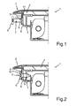
- Fig. 1 a partial section of a hob 1 is shown in a cross-sectional view.
- the hob 1 comprises a decorative frame 2 and a mounting frame 3, wherein between these two frames a hob plate 4 is arranged.
- This is formed for example of glass ceramic.
- the decorative frame 2 is located on an upper side of the hob plate 4, wherein the mounting frame 3 is arranged on an underside of the hob plate 4, so that the hob plate 4 rests on this sub-element of the mounting frame 3.
- the decorative frame 2 comprises a vertically extending web 5, which extends substantially parallel to the vertically extending web 6 of the mounting frame 3.
- the web 5 is positioned on the outside of the web 6.
- the decorative frame 2 and the mounting frame 3 are formed in the embodiment of four-cornered and on each side a plurality of compounds are formed. These connections are realized by self-tapping screws 7, wherein at least three such self-tapping screws 7 are formed on each of the sides of the four-bar.
- the self-tapping screw 7 has a tapered threaded portion 8 and a flat head 9.
- the special screw 7 is formed with a torque exceeding 500 Ncm.
- a continuous bore 10 is formed in the decorative frame 2, in particular in the vertical web 5.
- a hole-free region 11 is provided in this vertical web 6, and thus formed no continuous bore.
- the screw 7 is as shown Fig. 1 machine-guided to the connection position, passed through the bore 10 of the decorative frame 2 and attached to the hole-free area 11.
- the vertical web 5 of the decorative frame 2 is formed hole-free in the connection region and thus the bore 10 is not present.
- the self-tapping screw 7 is then rotated through both webs 5 and 6 at the specific connection region. Even if the connection area is not visible and signaled through the bore 10, and also the web 5 is formed hole-free on the connection area, can be found by the machine-controlled pre-screw 7 yet the precise connection point and a corresponding screwing done automatically, and a high quality connection can be achieved.
Landscapes
- Engineering & Computer Science (AREA)
- Chemical & Material Sciences (AREA)
- Combustion & Propulsion (AREA)
- Mechanical Engineering (AREA)
- General Engineering & Computer Science (AREA)
- Connection Of Plates (AREA)
- Residential Or Office Buildings (AREA)
Applications Claiming Priority (1)
| Application Number | Priority Date | Filing Date | Title |
|---|---|---|---|
| DE200710044239 DE102007044239A1 (de) | 2007-09-17 | 2007-09-17 | Kochfeld mit einem Zierrahmen und einem damit verbundenen Montagerahmen und Verfahren zum Verbinden des Zierrahmens mit dem Montagerahmen |
Publications (2)
| Publication Number | Publication Date |
|---|---|
| EP2037182A2 true EP2037182A2 (fr) | 2009-03-18 |
| EP2037182A3 EP2037182A3 (fr) | 2010-09-08 |
Family
ID=40219936
Family Applications (1)
| Application Number | Title | Priority Date | Filing Date |
|---|---|---|---|
| EP08105228A Withdrawn EP2037182A3 (fr) | 2007-09-17 | 2008-09-04 | Champ de cuisson doté d'un châssis décoratif et d'un cadre de montage y étant raccordé et procédé de raccordement du châssis décoratif et du cadre de montage |
Country Status (2)
| Country | Link |
|---|---|
| EP (1) | EP2037182A3 (fr) |
| DE (1) | DE102007044239A1 (fr) |
Cited By (1)
| Publication number | Priority date | Publication date | Assignee | Title |
|---|---|---|---|---|
| RU2768337C2 (ru) * | 2017-07-11 | 2022-03-23 | Э.Г.О. Электро-Геретебау Гмбх | Конфорочное устройство, содержащее конфорку и варочную поверхность |
Families Citing this family (1)
| Publication number | Priority date | Publication date | Assignee | Title |
|---|---|---|---|---|
| DE102018212052A1 (de) | 2018-07-19 | 2020-01-23 | BSH Hausgeräte GmbH | Kochfeld, Gargerät und Verfahren zum Montieren eines Kochfelds an einem Gargerät |
Citations (4)
| Publication number | Priority date | Publication date | Assignee | Title |
|---|---|---|---|---|
| GB2186311A (en) * | 1986-02-12 | 1987-08-12 | Hotpoint Ltd | Decorative panels for domestic appliances |
| DE19854229A1 (de) | 1998-11-24 | 2000-05-25 | Bsh Bosch Siemens Hausgeraete | Kochfeld mit zweiteiligem Rahmen |
| DE19907048A1 (de) | 1999-02-19 | 2000-08-24 | Bsh Bosch Siemens Hausgeraete | Koch- oder Warmhaltegerät |
| DE10348427A1 (de) * | 2003-10-14 | 2005-05-19 | Volkswagen Ag | Verfahren und Vorrichtung zur Direktverschraubung |
Family Cites Families (4)
| Publication number | Priority date | Publication date | Assignee | Title |
|---|---|---|---|---|
| DE3104114C2 (de) * | 1981-02-06 | 1984-06-14 | Schott Glaswerke, 6500 Mainz | Halterung für eine Platte aus Glas, Glaskeramik oder ähnlichem Material, insbesondere für eine Kochfläche |
| DE9416558U1 (de) * | 1994-10-14 | 1994-12-01 | Gebr. Seppelfricke GmbH, 45881 Gelsenkirchen | Glaskochfeld |
| EP0963535A2 (fr) * | 1997-01-26 | 1999-12-15 | Horst Mosshammer Von Mosshaim | Montage en araignee |
| DE102006037241A1 (de) * | 2005-08-16 | 2007-04-12 | BSH Bosch und Siemens Hausgeräte GmbH | Kochgerät |
-
2007
- 2007-09-17 DE DE200710044239 patent/DE102007044239A1/de not_active Withdrawn
-
2008
- 2008-09-04 EP EP08105228A patent/EP2037182A3/fr not_active Withdrawn
Patent Citations (4)
| Publication number | Priority date | Publication date | Assignee | Title |
|---|---|---|---|---|
| GB2186311A (en) * | 1986-02-12 | 1987-08-12 | Hotpoint Ltd | Decorative panels for domestic appliances |
| DE19854229A1 (de) | 1998-11-24 | 2000-05-25 | Bsh Bosch Siemens Hausgeraete | Kochfeld mit zweiteiligem Rahmen |
| DE19907048A1 (de) | 1999-02-19 | 2000-08-24 | Bsh Bosch Siemens Hausgeraete | Koch- oder Warmhaltegerät |
| DE10348427A1 (de) * | 2003-10-14 | 2005-05-19 | Volkswagen Ag | Verfahren und Vorrichtung zur Direktverschraubung |
Cited By (1)
| Publication number | Priority date | Publication date | Assignee | Title |
|---|---|---|---|---|
| RU2768337C2 (ru) * | 2017-07-11 | 2022-03-23 | Э.Г.О. Электро-Геретебау Гмбх | Конфорочное устройство, содержащее конфорку и варочную поверхность |
Also Published As
| Publication number | Publication date |
|---|---|
| EP2037182A3 (fr) | 2010-09-08 |
| DE102007044239A1 (de) | 2009-03-19 |
Similar Documents
| Publication | Publication Date | Title |
|---|---|---|
| DE3242730C2 (fr) | ||
| EP2982580B1 (fr) | Procédé de fabrication d'un véhicule automobile et véhicule automobile | |
| DE102016106006B4 (de) | Vorrichtung zum Ausgleichen von Toleranzen | |
| EP2099257B1 (fr) | Champ de cuisson | |
| EP2037182A2 (fr) | Champ de cuisson doté d'un châssis décoratif et d'un cadre de montage y étant raccordé et procédé de raccordement du châssis décoratif et du cadre de montage | |
| EP4048909B1 (fr) | Dispositif de boîtier en matière plastique pour une connexion à vis indirecte pour un véhicule automobile | |
| EP2131111A1 (fr) | Procédé destiné à la fabrication d'un champ de cuisson, tout comme champ de cuisson | |
| DE102014223420A1 (de) | Steuergerät, System aus einem Steuergerät und einer das Steuergerät aufnehmenden Halterung, Verfahren zur Ausbildung einer Gehäusevariante eines Steuergerätes | |
| AT520816B1 (de) | Montagewinkel und Montageanordnung | |
| EP2590493B1 (fr) | Convertisseur de fréquence | |
| DE102010063151A1 (de) | Steuergerät und Verfahren zum Herstellen eines Steuergeräts | |
| EP2894357B1 (fr) | Écrou clips, système de fixation et procédé de fabrication d'un écrou clips | |
| EP2775231A1 (fr) | Etrier de montage | |
| DE102018217276A1 (de) | Anordnung zur Befestigung von Bauteilen an einem Metallguss-Bauteil | |
| DE102009050944A1 (de) | Dachantenne mit einer Befestigungsvorrichtung | |
| DE102021200241A1 (de) | Spielfreie Befestigung einer Leiterplatte | |
| DE102011004527A1 (de) | Befestigungsstift zur mechanischen Befestigung und elektrischen Anbindung einer Leiterplatte an einen metallischen Träger und Verfahren zur Herstellung eines solchen Verbunds | |
| EP1562296A2 (fr) | Appareil électronique à monter dans une automobile | |
| EP1645013B1 (fr) | Composant destine a une plaquette | |
| DE2415855A1 (de) | Schrauben- oder mutternsicherung | |
| EP3705738B1 (fr) | Système de fixation d'un composant en métal léger à l'aide d'une vis de la technique des matières plastiques et procédé de vissage des vis de la technique des matières plastiques dans les métaux légers | |
| EP4519142B1 (fr) | Dispositif et procédé de fixation pour fixer une vitre d'une fenêtre pour un véhicule ferroviaire, et fenêtre pour un véhicule ferroviaire | |
| DE4227670A1 (de) | Befestigungselement | |
| DE102005003186A1 (de) | Vorrichtung zum Verbinden von Bauelementen | |
| DE102024107824A1 (de) | Verschraubungssystem, schraubverbindung sowie bauteil-vorbohrung für eine schraubverbindung |
Legal Events
| Date | Code | Title | Description |
|---|---|---|---|
| PUAI | Public reference made under article 153(3) epc to a published international application that has entered the european phase |
Free format text: ORIGINAL CODE: 0009012 |
|
| AK | Designated contracting states |
Kind code of ref document: A2 Designated state(s): AT BE BG CH CY CZ DE DK EE ES FI FR GB GR HR HU IE IS IT LI LT LU LV MC MT NL NO PL PT RO SE SI SK TR |
|
| AX | Request for extension of the european patent |
Extension state: AL BA MK RS |
|
| PUAL | Search report despatched |
Free format text: ORIGINAL CODE: 0009013 |
|
| AK | Designated contracting states |
Kind code of ref document: A3 Designated state(s): AT BE BG CH CY CZ DE DK EE ES FI FR GB GR HR HU IE IS IT LI LT LU LV MC MT NL NO PL PT RO SE SI SK TR |
|
| AX | Request for extension of the european patent |
Extension state: AL BA MK RS |
|
| 17P | Request for examination filed |
Effective date: 20110308 |
|
| AKX | Designation fees paid |
Designated state(s): AT BE BG CH CY CZ DE DK EE ES FI FR GB GR HR HU IE IS IT LI LT LU LV MC MT NL NO PL PT RO SE SI SK TR |
|
| RAP1 | Party data changed (applicant data changed or rights of an application transferred) |
Owner name: BSH HAUSGERAETE GMBH |
|
| 17Q | First examination report despatched |
Effective date: 20160510 |
|
| STAA | Information on the status of an ep patent application or granted ep patent |
Free format text: STATUS: THE APPLICATION IS DEEMED TO BE WITHDRAWN |
|
| 18D | Application deemed to be withdrawn |
Effective date: 20170905 |