EP2037187A2 - Unité extérieure pour climatiseur - Google Patents
Unité extérieure pour climatiseur Download PDFInfo
- Publication number
- EP2037187A2 EP2037187A2 EP08252264A EP08252264A EP2037187A2 EP 2037187 A2 EP2037187 A2 EP 2037187A2 EP 08252264 A EP08252264 A EP 08252264A EP 08252264 A EP08252264 A EP 08252264A EP 2037187 A2 EP2037187 A2 EP 2037187A2
- Authority
- EP
- European Patent Office
- Prior art keywords
- accumulator
- outdoor unit
- unit according
- main body
- refrigerant
- Prior art date
- Legal status (The legal status is an assumption and is not a legal conclusion. Google has not performed a legal analysis and makes no representation as to the accuracy of the status listed.)
- Withdrawn
Links
Images


Classifications
-
- F—MECHANICAL ENGINEERING; LIGHTING; HEATING; WEAPONS; BLASTING
- F25—REFRIGERATION OR COOLING; COMBINED HEATING AND REFRIGERATION SYSTEMS; HEAT PUMP SYSTEMS; MANUFACTURE OR STORAGE OF ICE; LIQUEFACTION SOLIDIFICATION OF GASES
- F25B—REFRIGERATION MACHINES, PLANTS OR SYSTEMS; COMBINED HEATING AND REFRIGERATION SYSTEMS; HEAT PUMP SYSTEMS
- F25B40/00—Subcoolers, desuperheaters or superheaters
-
- F—MECHANICAL ENGINEERING; LIGHTING; HEATING; WEAPONS; BLASTING
- F24—HEATING; RANGES; VENTILATING
- F24F—AIR-CONDITIONING; AIR-HUMIDIFICATION; VENTILATION; USE OF AIR CURRENTS FOR SCREENING
- F24F1/00—Room units for air-conditioning, e.g. separate or self-contained units or units receiving primary air from a central station
- F24F1/06—Separate outdoor units, e.g. outdoor unit to be linked to a separate room comprising a compressor and a heat exchanger
- F24F1/46—Component arrangements in separate outdoor units
-
- F—MECHANICAL ENGINEERING; LIGHTING; HEATING; WEAPONS; BLASTING
- F24—HEATING; RANGES; VENTILATING
- F24F—AIR-CONDITIONING; AIR-HUMIDIFICATION; VENTILATION; USE OF AIR CURRENTS FOR SCREENING
- F24F13/00—Details common to, or for air-conditioning, air-humidification, ventilation or use of air currents for screening
- F24F13/20—Casings or covers
-
- F—MECHANICAL ENGINEERING; LIGHTING; HEATING; WEAPONS; BLASTING
- F25—REFRIGERATION OR COOLING; COMBINED HEATING AND REFRIGERATION SYSTEMS; HEAT PUMP SYSTEMS; MANUFACTURE OR STORAGE OF ICE; LIQUEFACTION SOLIDIFICATION OF GASES
- F25B—REFRIGERATION MACHINES, PLANTS OR SYSTEMS; COMBINED HEATING AND REFRIGERATION SYSTEMS; HEAT PUMP SYSTEMS
- F25B43/00—Arrangements for separating or purifying gases or liquids; Arrangements for vaporising the residuum of liquid refrigerant, e.g. by heat
- F25B43/006—Accumulators
Definitions
- the present disclosure relates to an outdoor unit of an air conditioner, which has an accumulator provided with a mounting unit to which a variety of other components can be coupled.
- an air conditioner is a cooling/heating system that cools an indoor environment by continually performing a cycle of suctioning warm air from the indoor environment, performing heat exchange between the air and cold refrigerant, and expelling the cooled air back into the indoor environment.
- the air conditioner defines a series of cycles using a compressor, condenser, expansion valve, and evaporator.
- the typical air conditioners may be divided largely into split type air conditioners with outdoor and indoor units that are installed separately from each other, and integrated type conditioners with the outdoor and indoor units that are integrally installed with each other.
- a relatively recent phenomenon is the widespread use of multi-unit air conditioners that are effectively applied in households wanting to install two or more air conditioners, and in buildings with multiple offices that require respective air conditioners.
- the multi-unit air conditioner connects one outdoor unit to a plurality of indoor units to achieve the same effect as a case where a plurality of the split type air conditioners are installed.
- a variety of components such as an accumulator and a super cooler in addition to the compressor are installed in the air conditioner.
- Such components are generally mounted on a base assembly defining a lower exterior of the outdoor unit.
- an outdoor unit of an air conditioner which has an accumulator on which a variety of components can be detachably mounted.
- an outdoor unit of an air conditioner includes a base assembly defining a lower exterior of the outdoor unit and supporting a plurality of components; and an accumulator that is installed above the base assembly to filter off liquefied refrigerant from refrigerant entering a compressor, wherein the accumulator comprises a mounting unit enabling at least one of other components to be mounted on the accumulator.
- the mounting unit is provided on a surface of the accumulator. Therefore, a component such as a super cooler can be mounted on the accumulator by the mounting unit, an overall size of the air conditioner can be reduced.
- an internal space of the outdoor unit and the base assembly can be downsized.
- the mounting unit provided on the accumulator may be designed such that an end of the component can be hooked on the accumulator. Therefore, since a screw-coupling work can be conveniently performed in a state where the end of the component is hooked on the accumulator, the working efficiency can be improved.
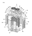
- FIG. 1 is a perspective view of an outdoor unit according to an exemplary embodiment of the present disclosure. Specifically, FIG. 1 exemplarily shows a type of outdoor unit for an air conditioner that discharges air upwards.
- the outdoor unit 10 is formed in a box shape and connected through pipes to a plurality of indoor units (not shown). Refrigerant flows between the outdoor and indoor units.
- the outdoor unit 10 includes a base assembly 100 defining a lower exterior and a cabinet 200 defining an upper exterior. That is, the cabinet 200 is disposed on the base assembly 100.
- the outdoor unit 10 further includes an outlet grills G having an octagonal shape (when viewed from a top) and protruding upward from a top surface of the cabinet 200. The air is discharged out of the outdoor unit 10 through the outlet grills G.
- FIG. 2 is an exploded perspective view of the outdoor unit 10.
- the cabinet 200 is formed with a plurality panels.
- the cabinet 200 includes a pair of front panels 210 and 212 that are provided at a front end of the base assembly 100 to define a front exterior of the outdoor unit. That is, the front panels 210 and 212 are respectively installed on left and right sides at the front end of the base assembly 100.
- a front center frame 220 is vertically elongated between the front panels 210 and 212.
- the cabinet 200 further includes a pair of front upper panels 230 and 232 provided above the respective front panels 210 and 212.
- the front upper panels 230 and 232 define a front upper exterior of the outdoor unit and are installed at the left and right above the respective panels 210 and 212, respectively.
- a front upper frame 240 is further provided between the front upper panels 230 and 232.
- the front upper frame 240 is shaped correspondingly to the front center frame 220 to support the pair of front upper panels 230 and 232.
- a left panel 250 and a right panel 260 are respectively provided at the left and right ends of the base assembly 100, defining left and right external facets of the outdoor unit. Also, a left grill 252 is integrally formed with the left panel 250, and a right grill 262 is integrally formed with the left panel 260. Thus, external air is able to enter the outdoor unit 10 through the left and right grills 252 and 262.
- a pair of rear grills 270 is provided at an upper rear end of the base assembly 100.
- the rear grills 270 define the rear exterior surface, and the external air also enters the outdoor unit 10 through the rear grills 270.
- a rear center frame (not shown) corresponding to the front center frame 220 is further provided at a central portion of the rear grills 270 to support the pair of rear grills 270.
- a pair of top panels 280 and 282 is provided between top ends of the left and right panels 250 and 260 to define the top exterior of the outdoor unit. That is, the external top surface of the outdoor unit 10 is defined by the rectangular left top panel 280 and right top panel 282.
- An outlet 284 is defined vertically through each of the pair of top panels 280 and 282.
- outlet grills G are installed on the outlets 284.
- the outlet grills G prevent impurities from the outside from entering through the outlets 284, and also allow the air to be discharged upwards out of the outdoor unit.
- a pair of rear upper panels 290 and 292 is further provided at the top of the pair of rear grills 270.
- the rear upper panels 290 and 292 define the rear upper exterior of the outdoor unit, and are formed to have a shape corresponding to the front upper panels 230 and 232.
- the rear upper panels 290 and 292 are respectively disposed at left and right sides, and a rear upper frame 294 is further provided between the rear upper panels 290 and 292.
- the rear upper frame 294 is formed in a shape corresponding to the front upper frame 240, and supports the pair of rear upper panels 290 and 292.
- a frame assembly 300 is provided within the cabinet 200.
- the frame assembly 300 is installed on upper ends of the front panels 210 and 212 to support shrouds 420 and 422, a blower fan 400, and other components, which will be described below.
- a pair of blower fan 400 and a fan motor 410 are installed at the top of the frame assembly 300.
- the pair of blower fans 400 is enclosed by a pair of shrouds 420 and 422. That is, the shrouds 420 and 422 having the same shape are installed on left and right sides at the top of the frame assembly 300, and the blower fan 400 is disposed to the inside of the pair of shrouds 420 and 422.
- a heat exchanger 450 is installed within the cavity 200.
- the heat exchanger 450 functions to exchange heat between refrigerant flowing therein and air from the outside, and is installed on the upper left end, rear end, and right end of the base assembly 100. That is, the heat exchanger 450 is formed in a ' ⁇ ' shape, that is an inverted "U" shape, as shown (when viewed from above).
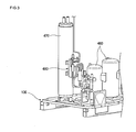
- FIG. 3 is a partial perspective view illustrating an installed state of a component on the base assembly 100.
- a compressor 460 for compressing refrigerant is installed on the base assembly 100 and an accumulator 470 for filtering liquefied refrigerant from the refrigerant flowing toward the compressor 460 is installed beside the compressor 460 on the base assembly 100.
- a super cooler 480 is fixedly coupled to a surface of the accumulator 470.
- the super cooler 480 serves to further cool the refrigerant that is cooled as it passes through the heat exchanger 450.
- a plate heat exchanger may be used as the super cooler 480.
- the plate heat exchanger includes a plurality of thin plates that are spaced apart from each other at predetermined intervals to define spaces along which the refrigerant and cooling water flow. Refrigerant flows through each of the spaces defined between the plurality of thin plates to perform heat exchange.
- FIG. 4 is an exploded perspective view of the accumulator 470 and the super cooler 480.
- the accumulator 470 includes a main body 472 defining a refrigerant receiving chamber and inlet and outlet pipes 474 and 476 that communicate with the refrigerant receiving chamber defined by the main body 472 to guide the flow of the refrigerant into or out of the main body 472, inside of the main body 472.
- the main body 472 is formed in a cylindrical shape and erected upright.
- the inlet pipe 474 penetrates the top of the main body 474.
- a lower end portion of the inlet pipe 474 is bent toward an inner wall of the main body 474.
- the outlet pipe 476 is also formed to penetrate the top of the main body 472 and partly projected above the top of the main body 472.
- a plurality of supporting legs (e.g., three or four legs) 478 are formed on a lower end of the main body 472.
- the supporting legs 478 support the accumulator 470 on the base assembly 100.
- the accumulator 470 is provided with a mounting unit on which at least one component such as the super cooler 480 or other components can be supported.
- the mounting unit is provided on, for example, an outer circumference of the main body 470.
- the mounting unit includes a hook unit 500 by which the component (e.g., the super cooler 480) can be hooked on a surface of the main body 472 of the accumulator 470 and a coupling unit 510 for allowing a lower end of the super cooler 480 to be coupled to the surface of the main body 472 of the accumulator 470.
- the component e.g., the super cooler 480
- the hook unit 500 enables the super cooler 480 to be fixed in a state where the super cooler 480 is hooked on the outer circumference of the main body 472 of the accumulator 470.
- the hook unit 500 includes a pair of first hook members 502 formed on the outer circumference of the main body 472 of the accumulator 470 and a pair of second hook members 504 formed on an upper end of the super cooler 480.
- the first hook members 502 and the second hook members 504 are configured to be hooked one another.
- the first hook members 502 are respectively formed in ' ⁇ ' and ' ⁇ ' shapes, that is opposing "C" shapes (when viewed from a top) and the second hook members 504 are respectively formed in a ' ⁇ ' shape (when viewed from a side).
- the coupling unit 510 is for allowing the lower end of the super cooler 480 to be fixed on the outer circumference of the main body 472 of the accumulator 470 by, for example, screws.
- the coupling unit 510 includes first coupling members 512 formed on the main body 472 of the accumulator 470 and second coupling member 514 formed on a lower end of the super cooler 480.
- the first coupling members 512 is shaped to correspond to the second coupling members 514.
- the fist coupling members 512 are formed in a ' ⁇ ' shape (when viewed from a top)
- the second coupling member 514 are formed in a ' ⁇ ' shape (when viewed from a top). That is, the first coupling members 512 and the second coupling member 514 are formed in opposing "L" shapes.
- the first hook members 502 and the first coupling members 512 are provided at front surfaces with respective coupling holes 520 in which the screws are coupled.
- the second hook members 504 and the second coupling members 514 are provided at front surfaces with respective through holes 520 through which the screws pass.
- a worker lifts the super cooler 480 and moves downward the super cooler 480 in a state where the super cooler 480 closely contacts the outer circumference of the main body 472 of the accumulator 470. Then, the front surfaces of the first hook members 502 inserted into the second hook members 504 and thus the upper end of the super cooler 480 is hooked on the accumulator 470.
- the super cooler 480 maintains its hooked state on the main body. Therefore, the worker can do other works. That is, the worker inserts the screws into the through holes 522 of the second hook members 504 and couples the screws to the coupling holes 520, thereby completing the coupling of the upper end of the super cooler 480.
- the worker inserts the screws into the through holes 522 of the second coupling members 514 and then couples the screws to the coupling holes 520 of the first coupling members 512, thereby completing the coupling of the lower end of the super cooler 480.
- the mounting unit functions to guide an arrangement of electric wires as well as to mount the component on the accumulator 470. That is, a variety of wires of the outdoor unit may be hung on the mounting unit or fixed to the mounting unit by separate coupling members. Alternatively, the wires may be supported on the mounting unit by being knotted itself around the mounting unit.
- the super cooler 480 is coupled to the accumulator 470 by the mounting unit in the above embodiment, the present disclosure is not limited to the embodiment. That is, a variety of other components may be coupled to the accumulator 470 by the mounting unit.
- a dryer for removing moisture from the refrigerant a receiver that is disposed near an outlet of the heater exchanger 450 to store condensed, liquefied refrigerant, an oil separator for separating oil from the refrigerant discharged from the compressor 460, or the like may be mounted on the accumulator 470 by the mounting unit.
Landscapes
- Engineering & Computer Science (AREA)
- Mechanical Engineering (AREA)
- General Engineering & Computer Science (AREA)
- Chemical & Material Sciences (AREA)
- Physics & Mathematics (AREA)
- Thermal Sciences (AREA)
- Combustion & Propulsion (AREA)
- Analytical Chemistry (AREA)
- Power Engineering (AREA)
- Other Air-Conditioning Systems (AREA)
- Heat-Exchange Devices With Radiators And Conduit Assemblies (AREA)
Applications Claiming Priority (1)
| Application Number | Priority Date | Filing Date | Title |
|---|---|---|---|
| KR1020070093334A KR20090028064A (ko) | 2007-09-13 | 2007-09-13 | 공기조화기의 실외기 |
Publications (2)
| Publication Number | Publication Date |
|---|---|
| EP2037187A2 true EP2037187A2 (fr) | 2009-03-18 |
| EP2037187A3 EP2037187A3 (fr) | 2012-04-04 |
Family
ID=39831675
Family Applications (1)
| Application Number | Title | Priority Date | Filing Date |
|---|---|---|---|
| EP08252264A Withdrawn EP2037187A3 (fr) | 2007-09-13 | 2008-07-02 | Unité extérieure pour climatiseur |
Country Status (3)
| Country | Link |
|---|---|
| EP (1) | EP2037187A3 (fr) |
| KR (1) | KR20090028064A (fr) |
| CN (1) | CN101387427B (fr) |
Cited By (4)
| Publication number | Priority date | Publication date | Assignee | Title |
|---|---|---|---|---|
| EP3034959A1 (fr) * | 2014-12-17 | 2016-06-22 | LG Electronics Inc. | Dispositif extérieur pour climatiseur |
| US10041704B2 (en) | 2014-09-12 | 2018-08-07 | Lg Electronics Inc. | Outdoor device for an air conditioner |
| US10077910B2 (en) | 2014-09-12 | 2018-09-18 | Lg Electronics Inc. | Outdoor device for an air conditioner |
| US12203667B2 (en) | 2021-03-31 | 2025-01-21 | Daikin Industries, Ltd. | Air conditioner |
Families Citing this family (7)
| Publication number | Priority date | Publication date | Assignee | Title |
|---|---|---|---|---|
| KR102283550B1 (ko) * | 2014-12-31 | 2021-07-30 | 엘지전자 주식회사 | 공기 조화기의 실외기 |
| CN105180306B (zh) * | 2015-09-24 | 2019-01-25 | 珠海格力电器股份有限公司 | 安装底座及具有该安装底座的空调器 |
| CN105352235B (zh) * | 2015-11-24 | 2018-01-16 | 芜湖豫新世通汽车空调有限公司 | 防歪斜的储液干燥器组件 |
| CN108826514B (zh) * | 2018-08-23 | 2023-08-11 | 宁波奥克斯电气股份有限公司 | 一体式固定支架、油分气分固定组件及空调器 |
| CN109186136A (zh) * | 2018-11-08 | 2019-01-11 | 珠海格力节能环保制冷技术研究中心有限公司 | 一种压缩机组件和空调器 |
| KR20220049908A (ko) | 2020-10-15 | 2022-04-22 | 삼성전자주식회사 | 공기조화기 |
| KR20230075271A (ko) * | 2021-11-22 | 2023-05-31 | 삼성전자주식회사 | 열 교환기 조립체와 열 교환기 조립체를 포함하는 실외기 |
Family Cites Families (6)
| Publication number | Priority date | Publication date | Assignee | Title |
|---|---|---|---|---|
| US4888962A (en) * | 1989-01-06 | 1989-12-26 | Tecumseh Products Company | Suction accumulator strap |
| DE19543463C2 (de) * | 1995-11-22 | 1998-07-16 | Ford Werke Ag | Kältemittelsammler |
| JPH09243115A (ja) * | 1996-03-13 | 1997-09-16 | Sanyo Electric Co Ltd | 熱交換ユニット |
| US5850743A (en) * | 1996-11-13 | 1998-12-22 | Tecumseh Products Company | Suction accumulator assembly |
| US6378327B1 (en) * | 1999-09-30 | 2002-04-30 | Visteon Global Technologies, Inc. | Accumulator insulator bracket |
| JP4569041B2 (ja) * | 2000-07-06 | 2010-10-27 | 株式会社デンソー | 車両用冷凍サイクル装置 |
-
2007
- 2007-09-13 KR KR1020070093334A patent/KR20090028064A/ko not_active Ceased
-
2008
- 2008-07-02 EP EP08252264A patent/EP2037187A3/fr not_active Withdrawn
- 2008-07-11 CN CN2008101335346A patent/CN101387427B/zh not_active Expired - Fee Related
Cited By (5)
| Publication number | Priority date | Publication date | Assignee | Title |
|---|---|---|---|---|
| US10041704B2 (en) | 2014-09-12 | 2018-08-07 | Lg Electronics Inc. | Outdoor device for an air conditioner |
| US10077910B2 (en) | 2014-09-12 | 2018-09-18 | Lg Electronics Inc. | Outdoor device for an air conditioner |
| EP3034959A1 (fr) * | 2014-12-17 | 2016-06-22 | LG Electronics Inc. | Dispositif extérieur pour climatiseur |
| US10443902B2 (en) | 2014-12-17 | 2019-10-15 | Lg Electronics Inc. | Outdoor device for an air conditioner |
| US12203667B2 (en) | 2021-03-31 | 2025-01-21 | Daikin Industries, Ltd. | Air conditioner |
Also Published As
| Publication number | Publication date |
|---|---|
| CN101387427B (zh) | 2010-12-08 |
| KR20090028064A (ko) | 2009-03-18 |
| EP2037187A3 (fr) | 2012-04-04 |
| CN101387427A (zh) | 2009-03-18 |
Similar Documents
| Publication | Publication Date | Title |
|---|---|---|
| EP2037187A2 (fr) | Unité extérieure pour climatiseur | |
| US8092156B2 (en) | Outdoor unit of air conditioner | |
| US7185513B2 (en) | Low profile evaporator coil | |
| EP2056029A2 (fr) | Climatiseur | |
| US20080314068A1 (en) | Outdoor unit of air conditioner | |
| KR102077570B1 (ko) | 공기조화기의 실내기 | |
| KR20080075258A (ko) | 공기조화기 | |
| CN212252861U (zh) | 一种空调器 | |
| KR101911954B1 (ko) | 공기 조화기의 실내기 및 그의 조립방법 | |
| KR100626455B1 (ko) | 멀티형 공기조화기 | |
| CN216744600U (zh) | 吊装式空调室内机 | |
| KR100593080B1 (ko) | 멀티형 공기조화기의 실외기 | |
| CN222012123U (zh) | 风管机 | |
| CN215175502U (zh) | 天花机及空调器 | |
| CN217876165U (zh) | 空调室内机 | |
| KR100593079B1 (ko) | 멀티형 공기조화기의 실외기 | |
| KR200156393Y1 (ko) | 창문형 에어콘 | |
| CN110925887A (zh) | 空调 | |
| KR100593083B1 (ko) | 공기조화기의 실외기 시스템 | |
| KR102297911B1 (ko) | 덕트형 공기조화기 | |
| KR100584284B1 (ko) | 공기조화기 실외기의 상면판넬 결합구조 | |
| KR20050075152A (ko) | 멀티형 공기조화기의 실외기 | |
| KR20070077409A (ko) | 공기조화기의 실외기 | |
| KR20080058782A (ko) | 멀티형 공기조화기 | |
| KR100671568B1 (ko) | 멀티형 공기조화기의 실외기 |
Legal Events
| Date | Code | Title | Description |
|---|---|---|---|
| PUAI | Public reference made under article 153(3) epc to a published international application that has entered the european phase |
Free format text: ORIGINAL CODE: 0009012 |
|
| AK | Designated contracting states |
Kind code of ref document: A2 Designated state(s): AT BE BG CH CY CZ DE DK EE ES FI FR GB GR HR HU IE IS IT LI LT LU LV MC MT NL NO PL PT RO SE SI SK TR |
|
| AX | Request for extension of the european patent |
Extension state: AL BA MK RS |
|
| PUAL | Search report despatched |
Free format text: ORIGINAL CODE: 0009013 |
|
| AK | Designated contracting states |
Kind code of ref document: A3 Designated state(s): AT BE BG CH CY CZ DE DK EE ES FI FR GB GR HR HU IE IS IT LI LT LU LV MC MT NL NO PL PT RO SE SI SK TR |
|
| AX | Request for extension of the european patent |
Extension state: AL BA MK RS |
|
| RIC1 | Information provided on ipc code assigned before grant |
Ipc: F25B 43/00 20060101ALI20120228BHEP Ipc: F24F 13/20 20060101ALI20120228BHEP Ipc: F24F 1/00 20110101AFI20120228BHEP |
|
| AKY | No designation fees paid | ||
| REG | Reference to a national code |
Ref country code: DE Ref legal event code: R108 |
|
| REG | Reference to a national code |
Ref country code: DE Ref legal event code: R108 Effective date: 20121212 |
|
| STAA | Information on the status of an ep patent application or granted ep patent |
Free format text: STATUS: THE APPLICATION IS DEEMED TO BE WITHDRAWN |
|
| 18D | Application deemed to be withdrawn |
Effective date: 20121005 |