EP2037195A2 - Appareil de réfrigération - Google Patents
Appareil de réfrigération Download PDFInfo
- Publication number
- EP2037195A2 EP2037195A2 EP08252985A EP08252985A EP2037195A2 EP 2037195 A2 EP2037195 A2 EP 2037195A2 EP 08252985 A EP08252985 A EP 08252985A EP 08252985 A EP08252985 A EP 08252985A EP 2037195 A2 EP2037195 A2 EP 2037195A2
- Authority
- EP
- European Patent Office
- Prior art keywords
- evaporator
- side region
- disposed
- refrigerating apparatus
- flow route
- Prior art date
- Legal status (The legal status is an assumption and is not a legal conclusion. Google has not performed a legal analysis and makes no representation as to the accuracy of the status listed.)
- Withdrawn
Links
- XLYOFNOQVPJJNP-UHFFFAOYSA-N water Substances O XLYOFNOQVPJJNP-UHFFFAOYSA-N 0.000 claims abstract description 10
- 239000003507 refrigerant Substances 0.000 claims description 26
- 238000011144 upstream manufacturing Methods 0.000 claims description 13
- 230000008020 evaporation Effects 0.000 claims description 7
- 238000001704 evaporation Methods 0.000 claims description 7
- 238000010438 heat treatment Methods 0.000 description 4
- 238000013459 approach Methods 0.000 description 3
- 238000010586 diagram Methods 0.000 description 3
- 238000010257 thawing Methods 0.000 description 3
- 238000001816 cooling Methods 0.000 description 2
- 230000003321 amplification Effects 0.000 description 1
- 238000005265 energy consumption Methods 0.000 description 1
- 235000013305 food Nutrition 0.000 description 1
- 238000007710 freezing Methods 0.000 description 1
- 230000008014 freezing Effects 0.000 description 1
- 239000012212 insulator Substances 0.000 description 1
- 238000003199 nucleic acid amplification method Methods 0.000 description 1
Images
Classifications
-
- F—MECHANICAL ENGINEERING; LIGHTING; HEATING; WEAPONS; BLASTING
- F25—REFRIGERATION OR COOLING; COMBINED HEATING AND REFRIGERATION SYSTEMS; HEAT PUMP SYSTEMS; MANUFACTURE OR STORAGE OF ICE; LIQUEFACTION SOLIDIFICATION OF GASES
- F25D—REFRIGERATORS; COLD ROOMS; ICE-BOXES; COOLING OR FREEZING APPARATUS NOT OTHERWISE PROVIDED FOR
- F25D21/00—Defrosting; Preventing frosting; Removing condensed or defrost water
- F25D21/04—Preventing the formation of frost or condensate
Definitions
- the invention relates to a refrigerating apparatus with an electric field-generating unit.
- a refrigerating apparatus includes a storage compartment, a fan, and a refrigerating unit.
- the storage compartment has an evaporator-side region and a cooling-side region that is used to store, for example, foods.
- the refrigerating unit includes an evaporator disposed in the evaporator-side region of the storage compartment, a compressor, a condenser, and an expansion valve.
- a thermodynamic cycle is performed in the refrigerating unit. In this cycle, a circulating refrigerant enters the compressor as a low-pressure vapor. The vapor is compressed and exits the compressor as a superheated high-pressure vapor.
- the superheated vapor travels through the condenser which removes the superheat and then condenses the vapor into a liquefied refrigerant.
- the expansion valve By passing through the expansion valve, the liquefied refrigerant expands from the high-pressure level in the condenser to the low-pressure level in the evaporator, thereby resulting in flash evaporation.
- the liquefied refrigerant is completely vaporized in the evaporator by cooling the warm air from the cooling-side region, such that the cooling-side region can be maintained at a low temperature.
- the resulting refrigerant vapor returns to the compressor to complete the cycle.
- ice builds up on a conduit body of the evaporator.
- the ice on the evaporator acts as an insulator and reduces heat transfer between the evaporator and the air passing therethrough, thereby reducing the efficiency of the refrigerating apparatus.
- a heating element providing heat to melt ice off the evaporator is connected to the evaporator or is disposed at a position adjacent thereto. Normally, the heating element is controlled through a timer or a sensor.
- the prior art approaches require the expenditure of heating and are time consuming. Since the temperature in the storage compartment is likely to be unstable using the heating approach for defrosting, most large chest freezers require manual defrosting.
- an object of this invention is to provide a refrigerating apparatus that can overcome the aforesaid drawbacks associated with the prior art.
- a refrigerating apparatus of the present invention comprises: a storage compartment, an air-circulating member, a refrigerating unit, and an electric field-generating unit.
- the storage compartment includes an evaporator-side region and a cooling-side region.
- the air-circulating member is disposed to establish an air circulation path in which a to-be-cooled air flows from the cooling-side region to the evaporator-side region along an onward flow route, and in which a cooled air flows from the evaporator-side region back to the cooling-side region along a backward flow route.
- the refrigerating unit includes: an evaporator having a conduit body disposed in the evaporator-side region for evaporation of a refrigerant, and inlet and outlet members which are disposed upstream and downstream of the conduit body respectively to lead the refrigerant in and out of the conduit body, respectively; a compressor which is disposed outwardly of the storage compartment, which is positioned downstream of the outlet member to compress the vapor of refrigerant led out thereof for supply of liquefied refrigerant, and which is upstream of the inlet member for delivering the liquefied refrigerant towards the inlet member; and an expansion valve which is disposed downstream of the compressor and upstream of the inlet member for flash evaporation of the liquefied refrigerant.
- the electric field-generating unit is disposed to impose a DC voltage over the onward flow route with a sufficient intensity such that water droplets entrained in the to-be-cooled air are charged so as to minimize cohesion of water droplets in the evaporator-side region, thereby reducing phenomenon of frosting on the conduit body of the evaporator.
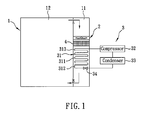
- a refrigerating apparatus in the first preferred embodiment, is shown to include a storage compartment 1, an air-circulating member 2, a refrigerating unit 3, and an electric field-generating unit 4.
- the storage compartment 1 has an evaporator-side region 11 and a cooling-side region 12.
- the air-circulating member 2 is disposed in the evaporator-side region 11 to establish an air circulation path in which a to-be-cooled air flows from the cooling-side region 12 to the evaporator-side region 11 along an onward flow route (A), and in which a cooled air flows from the evaporator-side region 11 back to the cooling-side region 12 along a backward flow route (B).
- the refrigerating unit 3 includes an evaporator 31, a compressor 32, a condenser 33, and an expansion valve 34.
- the evaporator 31 has a conduit body 311, and inlet and outlet members 312, 313.
- the conduit body 311 is disposed in the evaporator-side region 11 for evaporation of a refrigerant.
- the inlet and outlet members 312, 313 are disposed upstream and downstream of the conduit body 311 respectively to lead the refrigerant in and out of the conduit body 311, respectively.
- the refrigerant evaporates in the conduit body 311 as the heat is transferred from the to-be-cooled air to the refrigerant through the conduit body 311 of the evaporator 31.
- the cooled air then flows back to the cooling-side region 12 so as to maintain the storage compartment 1 of the refrigerating apparatus at a relatively low temperature.
- the compressor 32 is disposed outwardly of the storage compartment 1, and is positioned downstream of the outlet member 313 to compress the vapor of refrigerant as a superheated high-pressure vapor.
- the condenser 33 is also disposed outwardly of the storage compartment 1, and is positioned downstream of the compressor 32 and upstream of the expansion valve 34 to condense the superheated high-pressure vapor into a liquefied refrigerant.
- the liquefied refrigerant is delivered towards the expansion valve 34 disposed downstream of the condenser 33 and upstream of the inlet member 312 for flash evaporation of the liquefied refrigerant, followed by delivery of the refrigerant into the evaporator 31.
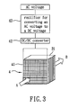
- the electric field-generating unit 4 includes a rectifier 43, a DC/DC converter 42, and a voltage grid 41 disposed upstream of the evaporator 31 in the onward flow route (A).
- the number of the voltage grid 41 is not limited.
- An external AC voltage is converted to a DC voltage using the rectifier 43, followed by amplification of the DC voltage to a desired high voltage using the DC/DC converter 42.
- the high voltage is applied to the voltage grid 41 such that water droplets entrained in the to-be-cooled air passing through the voltage grid 41 are charged so as to minimize cohesion of water droplets in the evaporator-side region 11, thereby reducing phenomenon of frosting on the conduit body 311 of the evaporator 31.
- the high voltage ranges from 3000V to 5000V.
- the air-circulating member 2 is disposed on the onward flow route (A) and upstream of the electric field-generating unit 4.
- the air-circulating member 2 is a ventilating fan.
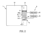
- Fig. 2 illustrates the second preferred embodiment of the refrigerating apparatus of this invention.
- the second preferred embodiment differs from the previous embodiment in that the air-circulating member 2 is disposed on the backward flow route (B) and downstream of the evaporator 31.
- the air-circulating member 2 is a ventilating fan.
Landscapes
- Engineering & Computer Science (AREA)
- Chemical & Material Sciences (AREA)
- Combustion & Propulsion (AREA)
- Physics & Mathematics (AREA)
- Mechanical Engineering (AREA)
- Thermal Sciences (AREA)
- General Engineering & Computer Science (AREA)
- Removal Of Water From Condensation And Defrosting (AREA)
- Defrosting Systems (AREA)
Applications Claiming Priority (1)
| Application Number | Priority Date | Filing Date | Title |
|---|---|---|---|
| TW96134035A TW200912225A (en) | 2007-09-12 | 2007-09-12 | Defrost-free device for refrigerating system |
Publications (2)
| Publication Number | Publication Date |
|---|---|
| EP2037195A2 true EP2037195A2 (fr) | 2009-03-18 |
| EP2037195A3 EP2037195A3 (fr) | 2011-04-13 |
Family
ID=39930546
Family Applications (1)
| Application Number | Title | Priority Date | Filing Date |
|---|---|---|---|
| EP08252985A Withdrawn EP2037195A3 (fr) | 2007-09-12 | 2008-09-10 | Appareil de réfrigération |
Country Status (2)
| Country | Link |
|---|---|
| EP (1) | EP2037195A3 (fr) |
| TW (1) | TW200912225A (fr) |
Family Cites Families (4)
| Publication number | Priority date | Publication date | Assignee | Title |
|---|---|---|---|---|
| DE1501111A1 (de) * | 1965-02-26 | 1970-04-02 | Gerhard Rausch | Vorrichtung zur Verhinderung von Vereisung der Verdampfer bei Kuehlaggregaten in Kuehlschraenken,Kuehltruhen,Kuehlraeumen u.dgl. |
| JPS57172124A (en) * | 1981-04-17 | 1982-10-22 | Hitachi Ltd | Heat exchanger of air conditioner |
| JPH06317366A (ja) * | 1993-05-07 | 1994-11-15 | Hitachi Ltd | 冷凍庫の空気冷却器 |
| DE10057006C1 (de) * | 2000-11-17 | 2002-05-23 | Friedhelm Meyer | Verfahren und Vorrichtung zum Betreiben von Klima- und Kälteanlagen |
-
2007
- 2007-09-12 TW TW96134035A patent/TW200912225A/zh unknown
-
2008
- 2008-09-10 EP EP08252985A patent/EP2037195A3/fr not_active Withdrawn
Also Published As
| Publication number | Publication date |
|---|---|
| TW200912225A (en) | 2009-03-16 |
| EP2037195A3 (fr) | 2011-04-13 |
Similar Documents
| Publication | Publication Date | Title |
|---|---|---|
| CN104613688B (zh) | 一种冰箱的热气除霜系统及其控制方法 | |
| US20100100243A1 (en) | Refrigerator and control method for the same | |
| US20240110733A1 (en) | Regrigerant charge control system for heat pump systems | |
| US4979371A (en) | Refrigeration system and method involving high efficiency gas defrost of plural evaporators | |
| US11092376B2 (en) | Refrigeration device comprising multiple storage chambers | |
| EP2554411B1 (fr) | Système de réfrigération pour véhicule et procédé de contrôle d'un système de réfrigération pour véhicule | |
| US9677789B2 (en) | Refrigeration appliance with two evaporators in different compartments | |
| EP2180277A3 (fr) | Contrôle de l'état de refroidissement d'un chargement | |
| US20170292770A1 (en) | Refrigeration system with fluid defrost | |
| US20160128241A1 (en) | Cooling device for a frequency converter, converter assembly comprising said cooling device and refrigerating or conditioning plant comprising said converter assembly | |
| US10443913B2 (en) | Refrigerator and method for controlling the same | |
| CN105135553A (zh) | 一种多联机系统和增加多联机系统的过冷度的方法 | |
| CN212362559U (zh) | 多元化制冷设备 | |
| US6250090B1 (en) | Apparatus and method for evaporator defrosting | |
| US20170292769A1 (en) | Refrigeration system with fluid defrost | |
| US20100205994A1 (en) | Refrigerating apparatus | |
| CN104132473A (zh) | 两级压缩不间断制热装置及两级压缩不间断制热融霜方法 | |
| US20190049164A1 (en) | Refrigerator And/Or Freezer Device | |
| KR101533644B1 (ko) | 핫가스 제상 냉동 사이클 장치 | |
| US10921045B2 (en) | Roll-bonded evaporator and method of forming the evaporator | |
| US20110219806A1 (en) | Refrigeration appliance comprising a plurality of shelves | |
| KR101962878B1 (ko) | 냉동기 토출 가스에 의한 응축 폐열 회수를 이용한 냉동 시스템 | |
| KR102713944B1 (ko) | 냉동 제상 사이클 장치 | |
| GB2532439A (en) | Improved air-source heat pump | |
| EP3859255B1 (fr) | Réfrigérateur |
Legal Events
| Date | Code | Title | Description |
|---|---|---|---|
| PUAI | Public reference made under article 153(3) epc to a published international application that has entered the european phase |
Free format text: ORIGINAL CODE: 0009012 |
|
| AK | Designated contracting states |
Kind code of ref document: A2 Designated state(s): AT BE BG CH CY CZ DE DK EE ES FI FR GB GR HR HU IE IS IT LI LT LU LV MC MT NL NO PL PT RO SE SI SK TR |
|
| AX | Request for extension of the european patent |
Extension state: AL BA MK RS |
|
| PUAL | Search report despatched |
Free format text: ORIGINAL CODE: 0009013 |
|
| AK | Designated contracting states |
Kind code of ref document: A3 Designated state(s): AT BE BG CH CY CZ DE DK EE ES FI FR GB GR HR HU IE IS IT LI LT LU LV MC MT NL NO PL PT RO SE SI SK TR |
|
| AX | Request for extension of the european patent |
Extension state: AL BA MK RS |
|
| AKY | No designation fees paid | ||
| REG | Reference to a national code |
Ref country code: DE Ref legal event code: R108 |
|
| REG | Reference to a national code |
Ref country code: DE Ref legal event code: R108 Effective date: 20111221 |
|
| STAA | Information on the status of an ep patent application or granted ep patent |
Free format text: STATUS: THE APPLICATION IS DEEMED TO BE WITHDRAWN |
|
| 18D | Application deemed to be withdrawn |
Effective date: 20111014 |