EP2037232A2 - Système et procédé pour l'étalonnage sur le terrain de débitmètres - Google Patents
Système et procédé pour l'étalonnage sur le terrain de débitmètres Download PDFInfo
- Publication number
- EP2037232A2 EP2037232A2 EP08158641A EP08158641A EP2037232A2 EP 2037232 A2 EP2037232 A2 EP 2037232A2 EP 08158641 A EP08158641 A EP 08158641A EP 08158641 A EP08158641 A EP 08158641A EP 2037232 A2 EP2037232 A2 EP 2037232A2
- Authority
- EP
- European Patent Office
- Prior art keywords
- flow meter
- transit time
- signal pulses
- calibration
- flow
- Prior art date
- Legal status (The legal status is an assumption and is not a legal conclusion. Google has not performed a legal analysis and makes no representation as to the accuracy of the status listed.)
- Withdrawn
Links
- 238000000034 method Methods 0.000 title claims description 32
- 238000004088 simulation Methods 0.000 claims abstract description 20
- 239000000523 sample Substances 0.000 claims description 100
- 239000012530 fluid Substances 0.000 claims description 96
- 238000012545 processing Methods 0.000 claims description 33
- 238000012937 correction Methods 0.000 claims description 21
- 238000003780 insertion Methods 0.000 claims description 7
- 230000037431 insertion Effects 0.000 claims description 7
- 238000011144 upstream manufacturing Methods 0.000 description 13
- 238000005259 measurement Methods 0.000 description 12
- 239000007789 gas Substances 0.000 description 10
- 230000006870 function Effects 0.000 description 6
- VNWKTOKETHGBQD-UHFFFAOYSA-N methane Chemical compound C VNWKTOKETHGBQD-UHFFFAOYSA-N 0.000 description 6
- 230000000670 limiting effect Effects 0.000 description 5
- XLYOFNOQVPJJNP-UHFFFAOYSA-N water Chemical compound O XLYOFNOQVPJJNP-UHFFFAOYSA-N 0.000 description 5
- 238000001311 chemical methods and process Methods 0.000 description 4
- 238000010586 diagram Methods 0.000 description 4
- 239000012080 ambient air Substances 0.000 description 3
- 239000003345 natural gas Substances 0.000 description 3
- 239000000654 additive Substances 0.000 description 2
- 230000000996 additive effect Effects 0.000 description 2
- 238000012993 chemical processing Methods 0.000 description 2
- 239000000356 contaminant Substances 0.000 description 2
- 230000003628 erosive effect Effects 0.000 description 2
- 230000002452 interceptive effect Effects 0.000 description 2
- 230000002411 adverse Effects 0.000 description 1
- 238000013459 approach Methods 0.000 description 1
- 230000005540 biological transmission Effects 0.000 description 1
- 230000015556 catabolic process Effects 0.000 description 1
- 238000002485 combustion reaction Methods 0.000 description 1
- 238000004891 communication Methods 0.000 description 1
- 238000010276 construction Methods 0.000 description 1
- 238000006731 degradation reaction Methods 0.000 description 1
- 239000012153 distilled water Substances 0.000 description 1
- 238000005516 engineering process Methods 0.000 description 1
- 230000007717 exclusion Effects 0.000 description 1
- 238000004519 manufacturing process Methods 0.000 description 1
- 238000012544 monitoring process Methods 0.000 description 1
- 238000005457 optimization Methods 0.000 description 1
- 230000000135 prohibitive effect Effects 0.000 description 1
- 238000010079 rubber tapping Methods 0.000 description 1
- 239000000126 substance Substances 0.000 description 1
- 238000012360 testing method Methods 0.000 description 1
- 238000012546 transfer Methods 0.000 description 1
Images



Classifications
-
- G—PHYSICS
- G01—MEASURING; TESTING
- G01F—MEASURING VOLUME, VOLUME FLOW, MASS FLOW OR LIQUID LEVEL; METERING BY VOLUME
- G01F1/00—Measuring the volume flow or mass flow of fluid or fluent solid material wherein the fluid passes through a meter in a continuous flow
- G01F1/66—Measuring the volume flow or mass flow of fluid or fluent solid material wherein the fluid passes through a meter in a continuous flow by measuring frequency, phase shift or propagation time of electromagnetic or other waves, e.g. using ultrasonic flowmeters
- G01F1/667—Arrangements of transducers for ultrasonic flowmeters; Circuits for operating ultrasonic flowmeters
- G01F1/668—Compensating or correcting for variations in velocity of sound
-
- G—PHYSICS
- G01—MEASURING; TESTING
- G01F—MEASURING VOLUME, VOLUME FLOW, MASS FLOW OR LIQUID LEVEL; METERING BY VOLUME
- G01F25/00—Testing or calibration of apparatus for measuring volume, volume flow or liquid level or for metering by volume
- G01F25/10—Testing or calibration of apparatus for measuring volume, volume flow or liquid level or for metering by volume of flowmeters
Definitions
- a flow meter measures flow velocity using two transducers which are located upstream and downstream from each other on a pipe or conduit. Each transducer transmits and receives in an alternating manner. Flow velocity is then computed as a function of the transit times of the ultrasonic signals both with and against the direction of flow, i.e. the difference between the upstream and downstream transit times. For example, in the presence of a flow, the transit time signal pulse transmitted from the upstream transducer to the downstream transducer is faster than the pulse transmitted from the downstream transducer to the upstream transducer. By subtracting the transit time from the downstream transducer to the upstream transducer from the transit time from the upstream transducer to the downstream transducer, the transit time differential ⁇ t is calculated. Utilizing other known parameters such as the conduit dimensions and ultrasonic signal path length, and the measured speed of sound in the fluid, flow velocity can thus be determined. The general principle of transit time measurement in ultrasonic flow meters is fairly well known.
- the probe includes at least one transducer and a reflector spaced a fixed distance apart and at least one aperture for the fluid to flow through the probe, the one probe transducer configured to transmit ultrasonic signals, receive ultrasonic signals reflected back from the reflector, and to output transit time signals.
- the flow meter may be a flare gas flow meter and the fluid may be a flare gas.
- the probe is portable, and may be pre-calibrated, and in one example the probe is less than or equal to 3 ⁇ 4 inches in diameter or width.
- the probe transducers may be moveable within the probe, or the reflector may be moveable within the probe.
- the processing subsystem is further configured to output a series of sound speeds representing a fluid sound speed profile.
- the subject invention further features a calibration system for a flow meter, the calibration system including a flow simulator including a receiver configured to receive flow meter transducer signals from a flow meter and a simulation subsystem configured to create simulated transit time signal pulses based on actual transit time signal pulses from the flow meter, and to transmit the simulated transit time signal pulses to the flow meter at preselected time intervals.
- a calibration subsystem is configured to receive from the flow meter a transit time differential value generated by the flow meter based on the simulated transit time signal pulses, compare the transit time differential value generated by the flow meter to a preselected time interval to compute a calibration factor, and output the calibration factor to the flow meter.
- the subject invention also features a calibration method for a flow meter including receiving flow meter transducer signals from a flow meter, creating simulated transit time signal pulses and transmitting the simulated transit time signal pulses to the flow meter at preselected time intervals, receiving from the flow meter a transit time differential value generated by the flow meter based on the simulated transit time signal pulses, and outputting a calibration factor to the flow meter.
- the preselected time interval may be representative of a transit time differential value for a particular type of fluid flowing at a known velocity.
- the flow meter transducer signals received are transmitted flow meter transducers signals, and the simulated transit time signal pulses are created using the transmitted flow meter transducer signals received from the flow meter.
- the simulated transit time signal pulses are based on actual flow meter transit time signal pulses from the flow meter.
- the method may include distorting the simulated transit time signal pulses to simulate noise factors interfering with the pulses, and/or modulating signal qualities of the simulated transit time signal pulses.
- the modulated signal qualities may include amplitude and/or frequency.
- the calibration method may further include inserting a probe into a conduit with fluid flowing therein, calculating the sound speed in the fluid, and outputting a sound speed correction factor to the flow meter.
- the probe is shaped to fit into an opening in the conduit, and in one configuration, the probe includes at least two transducers spaced a fixed distance apart and at least one aperture for the fluid to flow through the probe, the probe transducers configured to transmit and receive ultrasonic signals and to output transit time signals.
- the probe transducers typically define an ultrasonic signal path through the fluid.
- This invention further features a calibration method for a flow meter including receiving transmitted flow meter transducer signals from a flow meter, creating simulated transit time signal pulses using the transmitted flow meter transducer signals received from the flow meter and transmitting the simulated transit time signal pulses to the flow meter at preselected time intervals, receiving from the flow meter a transit time differential value generated by the flow meter based on the simulated transit time signal pulses, comparing the transit time differential value generated by the flow meter to a preselected time interval to compute a calibration factor to adjust the transit time differential value generated by the flow meter, and outputting the calibration factor to the flow meter.
- This invention also features a calibration method for a flow meter including receiving flow meter transducer signals from a flow meter, creating simulated transit time signal pulses based on actual transit time signals pulses from the flow meter and transmitting the simulated transit time signal pulses to the flow meter at preselected time intervals, receiving from the flow meter a transit time differential value generated by the flow meter based on the simulated transit time signal pulses, comparing the transit time differential value generated by the flow meter to a preselected time interval to compute a calibration factor, and outputting the calibration factor to the flow meter.
- This invention also features a calibration method for a flow meter including inserting a probe into an opening in a conduit with fluid flowing therein, calculating the sound speed in the fluid, and outputting a sound speed correction factor to a flow meter.
- the method further includes receiving flow meter transducer signals from the flow meter, creating simulated transit time signal pulses and transmitting the simulated transit time signal pulses to the flow meter at preselected time intervals, receiving from the flow meter a transit time differential value generated by the flow meter based on the simulated transit time signal pulses, and outputting a calibration factor to the flow meter.
- the method further includes receiving transmitted flow meter transducer signals from the flow meter, creating simulated transit time signal pulses using the transmitted flow meter transducer signals received from the flow meter, transmitting the simulated transit time signal pulses to the flow meter at preselected time intervals, receiving from the flow meter a transit time differential value generated by the flow meter based on the simulated transit time signal pulses, and outputting a calibration factor to the flow meter.
- flow meter calibration system 20 includes probe 30 and processing subsystem 40 for determining sound speed in fluid 24 flowing in conduit 18.
- flow meter calibration system 20 includes flow simulator 60 configured to simulate flow of a fluid, such as fluid 24 in one example.
- Other embodiments of flow meter calibration system 20 may include each of probe 30 and processing subsystem 40, as well as flow simulator 60, as discussed below.
- flow meter calibration system 20 calibrates flow meter 10 for improved accuracy of sound speed and/or velocity measurements in fluid 24, as well as other parameters which depend on such measurements.
- the embodiments of the subject invention are particularly suited to flare gas flow meters measuring flare gas, the invention is not so limited, and the embodiments of the system and method of the subject invention are not limited to use with any particular flow meter or a flow meter's particular configuration.
- a flow meter such as flow meter 10 measures fluid flow velocity of fluid 24 flowing in conduit 18 using two transducers 12 and 14, with transducer 12 located upstream and transducer 14 located downstream, each on or connected to pipe or conduit 18.
- each transducer 12, 14 is configured to transmit and receive ultrasonic signals in an alternating manner. The ultrasonic signals transmitted from one transducer are received by the other transducer and vice versa.
- flow velocity of fluid 24 through conduit 18 can be computed as a function of the transit times of the ultrasonic signals both with and against the direction of flow, i.e. the difference between the upstream and downstream ultrasonic signal transit times.
- the transit time signal pulse t dn transmitted from upstream transducer 12 to downstream transducer 14 is not the same as pulse t up transmitted from downstream transducer 14 to upstream transducer 12.
- speed of sound c in fluid 24 is an important factor in the determination of velocity V.
- Speed of sound c in fluid 24 is determined by the flow meter 10 using ultrasonic signal transit times. Erosion and degradation of flow meter components and/or deposits of contaminants accumulating over time, however, can adversely affect the accuracy of the sound speed determined by the flow meter, and consequently the fluid flow velocity V ascertained by the flow meter.
- calibration system 20 includes probe 30 for insertion into conduit 18 with fluid 24 flowing therein.
- probe 30 is shaped to fit into opening 31 in conduit 18.
- probe 30, Fig. 2A has a width or diameter w which is less than or equal to 3 ⁇ 4 inches for insertion of probe 30 into conduit 18. While tapping an opening of greater than 3 ⁇ 4 inches into an existing pipe is generally an expensive process requiring specialized personnel, under current regulations governing chemical process emissions, for example, conduit ports or openings up to 3 ⁇ 4 inches made by operators of the processing plant where the pipe is located are permissible. Thus, no specialized personnel are required, and such a port or opening can be easily and inexpensively prepared to allow for insertion of the probe into the pipe.
- the pipes of many chemical processing plants for example, include built-in ports of such size where the probe may be inserted.
- Flow meter calibration system 20 including probe 30 also includes processing subsystem 40 connected to probe 30 and configured to calculate sound speed in fluid 24 and output a sound speed correction factor to flow meter 10.
- processing subsystem 40 excites at least one of probe transducers 32 and 34 to transmit an ultrasonic signal.
- probe transducers 32 and 34 When probe 30 is fit or inserted into opening 31, Fig. 1 in conduit 18, apertures 36 and 38, Fig. 2 allow fluid flowing in the conduit to also flow through probe 30. Probe transducers 32 and 34 thus define an ultrasonic signal path through the fluid.
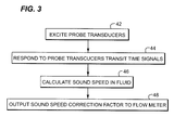
- FIG. 3 A summary of one configuration of the operation of processing subsystem 40 is shown in flowchart form in Fig. 3 .
- Probe transducers 30 and 32 are excited to transmit ultrasonic pulses or signals, step 42, and processing system 40 responds to the probe transducers transit time signals, step 44, calculates the speed of sound in the fluid, step 46, and outputs a sound speed correction factor to the flow meter, step 48.
- steps set forth in Fig. 3 are set forth in a particular sequence, it will be understood that this sequence is not limiting, and that steps may be undertaken simultaneously or out of order, steps may be eliminated or added in accordance with various embodiments, and that one or more steps may be achieved at least in part utilizing electronic circuitry.
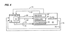
- flow simulator 60 is connected to flow meter processing and electronics 16 and includes receiver 62, simulation subsystem or module 64, and calibration subsystem or module 66.
- receiver 62 is configured to receive or capture flow meter transducer signals 68 and 68' from flow meter 10, typically transmitted flow meter transducer signals.
- simulated transit time signal pulses 70 and 70' are based on actual transit time signal pulses from flow meter 10, which have been captured and stored prior to calibration, and which are then later used by flow simulator 60 in its creation of simulated transit time signal pulses 70 and 70'. In this way, simulated signal pulses 70 and 70' are not pure, and since they are based on actual signals, will include signal characteristics peculiar to the particular flow meter which is the subject of the calibration.
- simulation subsystem 64 is further configured to distort simulated transit time signal pulses 70 and 70' to simulate noise factors which interfere with the pulses.
- simulation subsystem 64 is configured to modulate signal qualities of simulated transit time signal pulses 70 and 70', such as amplitude and/or frequency, for improved simulation and to create the various simulated signal pulses.
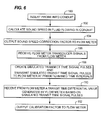
- Receiver 62 receives transmitted flow meter transducer signals 68, 68' from flow meter 10, step 80.
- simulation subsystem 64 uses transmitted flow meter transducer signals 68, 68' from flow meter 10, simulation subsystem 64 creates simulated transit time signal pulses 70 and 70', step 82, and transmits them to flow meter 10 at a preselected time interval, step 84.
- Calibration subsystem 66 receives transit time differential value 72 and/or velocity value 74 generated by flow meter 10 based on the simulated transit time signal pulses 70 and 70', step 86, and outputs calibration factor(s) 76 and/or 78 to the flow meter, step 88.
- a transit time differential value generated by the flow meter based on the simulated transit time signal pulses is received, step 110, for example by calibration subsystem 66, and a calibration factor is output to the flow meter, step 112.
Landscapes
- Physics & Mathematics (AREA)
- Fluid Mechanics (AREA)
- General Physics & Mathematics (AREA)
- Electromagnetism (AREA)
- Measuring Volume Flow (AREA)
Applications Claiming Priority (1)
| Application Number | Priority Date | Filing Date | Title |
|---|---|---|---|
| US11/774,215 US7984637B2 (en) | 2007-07-06 | 2007-07-06 | System and method for field calibration of flow meters |
Publications (2)
| Publication Number | Publication Date |
|---|---|
| EP2037232A2 true EP2037232A2 (fr) | 2009-03-18 |
| EP2037232A3 EP2037232A3 (fr) | 2009-05-27 |
Family
ID=40213195
Family Applications (1)
| Application Number | Title | Priority Date | Filing Date |
|---|---|---|---|
| EP08158641A Withdrawn EP2037232A3 (fr) | 2007-07-06 | 2008-06-20 | Système et procédé pour l'étalonnage sur le terrain de débitmètres |
Country Status (5)
| Country | Link |
|---|---|
| US (1) | US7984637B2 (fr) |
| EP (1) | EP2037232A3 (fr) |
| JP (1) | JP5292001B2 (fr) |
| CN (1) | CN101339068B (fr) |
| CA (1) | CA2635390C (fr) |
Families Citing this family (47)
| Publication number | Priority date | Publication date | Assignee | Title |
|---|---|---|---|---|
| EP2088932B1 (fr) | 2006-10-25 | 2020-04-08 | Maui Imaging, Inc. | Procédé et appareil de production d'images ultrasonores au moyen d'une pluralité d'orifices |
| US7661289B1 (en) * | 2007-08-31 | 2010-02-16 | Edc Biosystems, Inc. | Method for calibrating an acoustic droplet dispensing apparatus |
| US9282945B2 (en) | 2009-04-14 | 2016-03-15 | Maui Imaging, Inc. | Calibration of ultrasound probes |
| US9339256B2 (en) | 2007-10-01 | 2016-05-17 | Maui Imaging, Inc. | Determining material stiffness using multiple aperture ultrasound |
| US9788813B2 (en) | 2010-10-13 | 2017-10-17 | Maui Imaging, Inc. | Multiple aperture probe internal apparatus and cable assemblies |
| US9247926B2 (en) | 2010-04-14 | 2016-02-02 | Maui Imaging, Inc. | Concave ultrasound transducers and 3D arrays |
| WO2010057951A2 (fr) * | 2008-11-21 | 2010-05-27 | Flexim Flexible Industriemesstechnik Gmbh | Procédé et dispositif d'étalonnage de tranducteurs de mesure de débitmètres à ultrasons |
| US7942068B2 (en) * | 2009-03-11 | 2011-05-17 | Ge Infrastructure Sensing, Inc. | Method and system for multi-path ultrasonic flow rate measurement |
| JP5485373B2 (ja) | 2009-04-14 | 2014-05-07 | マウイ イマギング,インコーポレーテッド | 複数開口の超音波アレイ位置合せ装置 |
| KR102322776B1 (ko) | 2010-02-18 | 2021-11-04 | 마우이 이미징, 인코포레이티드 | 초음파 이미지를 구성하는 방법 및 이를 위한 다중-개구 초음파 이미징 시스템 |
| EP2383550A1 (fr) * | 2010-04-28 | 2011-11-02 | Miitors ApS | Débitmètre à ultrasons |
| AT509641B1 (de) | 2011-06-24 | 2012-08-15 | Avl List Gmbh | Verfahren zur ermittlung des durchflusses von fluiden nach dem ultraschalllaufzeitverfahren |
| JP6407719B2 (ja) | 2011-12-01 | 2018-10-17 | マウイ イマギング,インコーポレーテッド | ピングベース及び多数開口ドップラー超音波を用いた運動の検出 |
| EP2607864B8 (fr) | 2011-12-19 | 2017-08-02 | Endress+Hauser Consult AG | Procédé pour la vérification en ligne d'un débitmètre |
| JP2015503404A (ja) | 2011-12-29 | 2015-02-02 | マウイ イマギング,インコーポレーテッド | 任意経路のmモード超音波イメージング |
| CN102589627B (zh) * | 2012-02-23 | 2014-06-04 | 北京理工大学 | 一种用于超声波流量计的绝对传播时间测量方法 |
| EP2833791B1 (fr) | 2012-03-26 | 2022-12-21 | Maui Imaging, Inc. | Procédés pour l'amélioration de la qualité d'images ultrasonores par l'application de facteurs de pondération |
| EP2690461B1 (fr) * | 2012-07-26 | 2017-03-01 | Sercel | Procédé pour estimer la vitesse de l'eau d'un noeud acoustique |
| CN104620128B (zh) | 2012-08-10 | 2017-06-23 | 毛伊图像公司 | 多孔径超声探头的校准 |
| CN103676827A (zh) | 2012-09-06 | 2014-03-26 | Ip音乐集团有限公司 | 用于远程控制音频设备的系统和方法 |
| US9986969B2 (en) | 2012-09-06 | 2018-06-05 | Maui Imaging, Inc. | Ultrasound imaging system memory architecture |
| WO2014160291A1 (fr) | 2013-03-13 | 2014-10-02 | Maui Imaging, Inc. | Alignement de groupements de transducteurs à ultrasons et ensemble de sonde à ouvertures multiples |
| DK178244B1 (en) * | 2013-06-21 | 2015-09-28 | Agena As | A system or a method for measuring flow in a flow duct |
| US9883848B2 (en) | 2013-09-13 | 2018-02-06 | Maui Imaging, Inc. | Ultrasound imaging using apparent point-source transmit transducer |
| AU2015301406B2 (en) * | 2014-08-14 | 2020-07-16 | Reliance Worldwide Corporation | Methods and apparatus for fluid flow monitoring and leak detection |
| MX370819B (es) | 2014-08-14 | 2020-01-08 | Reliance Worldwide Corp | Dispositivos y sistemas para canalización y monitoreo automático de flujo de fluido en sistemas de distribución de fluido. |
| US10401493B2 (en) | 2014-08-18 | 2019-09-03 | Maui Imaging, Inc. | Network-based ultrasound imaging system |
| CN104596602A (zh) * | 2015-02-13 | 2015-05-06 | 广东奥迪威传感科技股份有限公司 | 超声波测量系统及其测量方法 |
| CN107613878B (zh) | 2015-03-30 | 2021-04-06 | 毛伊图像公司 | 用于检测物体运动的超声成像系统和方法 |
| PL3234514T3 (pl) * | 2015-08-28 | 2020-07-27 | Reliance Worldwide Corporation | Konfiguracja i kalibracja przepływomierza |
| US20170082480A1 (en) * | 2015-09-21 | 2017-03-23 | Honeywell International Inc. | Real-time condition based monitoring (cbm) based ultrasonic meter (usm) accuracy performance detection and notification |
| ES2873899T3 (es) | 2016-01-18 | 2021-11-04 | Gwf Messsysteme Ag | Caudalímetro de tiempo de recorrido con señal acústica mejorada de formación de haces |
| CN105547420A (zh) * | 2016-01-18 | 2016-05-04 | 成都千嘉科技有限公司 | 超声波燃气表流量点系数校正装置及方法 |
| EP4697068A3 (fr) | 2016-01-27 | 2026-04-22 | Maui Imaging, Inc. | Imagerie ultrasonore à sondes à matrice creuse |
| DE102016103419A1 (de) * | 2016-02-26 | 2017-08-31 | Krohne Messtechnik Gmbh | Messstab für den Nachweis eines strömenden Mediums in einem Rohr und diesbezügliche Messanordnung |
| CN106644844B (zh) * | 2016-09-30 | 2020-02-07 | 中国核动力研究设计院 | 一种液体用粒子分析仪检定装置的粒子分析仪检定方法 |
| US12036568B2 (en) * | 2018-06-11 | 2024-07-16 | Dh Technologies Development Pte. Ltd. | Volumetric measurement of micro droplets |
| CN113167617B (zh) * | 2018-11-30 | 2024-09-24 | 贝克休斯控股有限责任公司 | 原位超声流量计验证 |
| PL3929542T3 (pl) * | 2020-06-26 | 2023-11-06 | Sick Engineering Gmbh | Testowanie przepływomierza ultradźwiękowego |
| JP7724853B2 (ja) | 2020-10-21 | 2025-08-18 | マウイ イマギング,インコーポレーテッド | 多数開口超音波を用いた組織の特徴付けのためのシステム及び方法 |
| EP4236811A4 (fr) | 2020-11-02 | 2024-10-09 | Maui Imaging, Inc. | Systèmes et procédés d'amélioration de la qualité d'image ultrasonore |
| CN114235107B (zh) * | 2021-12-22 | 2024-11-19 | 北京奥特美克科技股份有限公司 | 一种明渠流量计量的校准方法和校准系统 |
| US20240248467A1 (en) * | 2023-01-20 | 2024-07-25 | Saudi Arabian Oil Company | Automatic online flaring data validation and reporting |
| CN116858346B (zh) * | 2023-09-05 | 2023-11-07 | 成都千嘉科技股份有限公司 | 基于超声波流量计的校准方法和校准装置 |
| CN117182038B (zh) * | 2023-09-11 | 2026-03-13 | 重庆长安汽车股份有限公司 | 一种用于微量油基脱模剂的流量异常预警方法及其系统 |
| US20250198816A1 (en) * | 2023-12-18 | 2025-06-19 | Sensia Netherlands B.V. | Systems and methods of high accuracy flow measurements |
| CN118882545B (zh) * | 2024-09-30 | 2025-01-28 | 山东省计量科学研究院 | 超声换能器声道长度复核计算的方法及系统 |
Family Cites Families (14)
| Publication number | Priority date | Publication date | Assignee | Title |
|---|---|---|---|---|
| US3981191A (en) * | 1975-07-05 | 1976-09-21 | Danfoss A/S | Method and apparatus for the ultrasonic measurement of the flow velocity of fluent media |
| SU792143A1 (ru) * | 1979-01-25 | 1980-12-30 | Каунасский Политехнический Институт Им.А.Снечкуса | Устройство дл градуировки и определени метрологических характеристик ультразвуковых измерителей скорости потока |
| US4509373A (en) * | 1983-06-09 | 1985-04-09 | Manning Technologies, Inc. | Calibration circuit for ultrasonic flowmeter |
| JPS62165122A (ja) * | 1986-01-17 | 1987-07-21 | Kawasaki Steel Corp | 透過形超音波流量計の較正方法 |
| US4729247A (en) * | 1986-12-19 | 1988-03-08 | Manning Technologies, Inc. | Universal doppler flowmeter tester |
| US4762012A (en) * | 1987-01-29 | 1988-08-09 | Manning Technologies, Inc. | Universal upstream-downstream flowmeter tester |
| JPH088417Y2 (ja) * | 1989-03-17 | 1996-03-06 | 株式会社カイジョー | 超音波流量計校正装置 |
| US4989446A (en) * | 1990-01-23 | 1991-02-05 | Dynatek Laboratories, Inc. | Ultrasound calibrator |
| JP3136002B2 (ja) * | 1992-09-08 | 2001-02-19 | 株式会社オーバル | 超音波流量計 |
| US5748504A (en) * | 1996-06-12 | 1998-05-05 | Welch Allyn, Inc. | Calibration method for use with ultrasonic flowmeters |
| JP3026770B2 (ja) * | 1997-02-27 | 2000-03-27 | 核燃料サイクル開発機構 | インライン酸濃度測定方法及び測定プローブ |
| JPH11351928A (ja) * | 1998-06-08 | 1999-12-24 | Yazaki Corp | 流量計および流量計測方法 |
| JP2005241407A (ja) * | 2004-02-26 | 2005-09-08 | Fuji Electric Systems Co Ltd | 超音波流量計の校正方法、超音波流速分布計の校正方法、超音波流量計、超音波流速分布計、検出器 |
| DE102004031274B4 (de) * | 2004-06-28 | 2007-07-12 | Flexim Flexible Industriemesstechnik Gmbh | Verfahren zur Kalibrierung von Ultraschall-Clamp-on-Durchflussmessgeräten |
-
2007
- 2007-07-06 US US11/774,215 patent/US7984637B2/en active Active
-
2008
- 2008-06-19 CA CA2635390A patent/CA2635390C/fr active Active
- 2008-06-20 EP EP08158641A patent/EP2037232A3/fr not_active Withdrawn
- 2008-07-04 JP JP2008175187A patent/JP5292001B2/ja not_active Expired - Fee Related
- 2008-07-07 CN CN2008101251001A patent/CN101339068B/zh not_active Expired - Fee Related
Also Published As
| Publication number | Publication date |
|---|---|
| CA2635390C (fr) | 2012-09-11 |
| JP2009014726A (ja) | 2009-01-22 |
| CA2635390A1 (fr) | 2009-01-06 |
| US20090007625A1 (en) | 2009-01-08 |
| CN101339068A (zh) | 2009-01-07 |
| CN101339068B (zh) | 2013-12-25 |
| EP2037232A3 (fr) | 2009-05-27 |
| US7984637B2 (en) | 2011-07-26 |
| JP5292001B2 (ja) | 2013-09-18 |
Similar Documents
| Publication | Publication Date | Title |
|---|---|---|
| US7984637B2 (en) | System and method for field calibration of flow meters | |
| EP2607864B1 (fr) | Procédé pour la vérification en ligne d'un débitmètre | |
| Geiger et al. | State-of-the-art in leak detection and localization | |
| RU2443010C1 (ru) | Способ определения приближающегося отказа преобразователей, система определения приближающегося отказа преобразователей (варианты) и машиночитаемый носитель информации | |
| EP2909587B1 (fr) | Système de mesure d'écoulement ultrasonore ayant un transducteur de pression amont | |
| US4109523A (en) | Method of determining acoustic flow meter correction factor | |
| EP3348968B1 (fr) | Appareil et procédé de mesure d'écoulement de gaz de torche | |
| US20080103629A1 (en) | Diagnostic device for use in process control system | |
| WO2008016697A2 (fr) | Procédé pour surveiller un fluide s'écoulant | |
| CN104136891A (zh) | 利用经补偿的计算温度的超声流动计量 | |
| EP2428776B1 (fr) | Procédé et appareil pour mesurer la vitesse de débit d'un gaz | |
| US6816808B2 (en) | Peak switch detector for transit time ultrasonic meters | |
| JP5569383B2 (ja) | 脈動流の流量測定方法およびガス流量測定装置 | |
| US6813588B1 (en) | Control system and method for detecting plugging in differential pressure cells | |
| CN106768104A (zh) | 一种超声波质量流量计 | |
| US20250198817A1 (en) | High sensitivity ultrasonic flow meter | |
| KR20160128220A (ko) | 초음파식 적산 열량계 | |
| JPH06186124A (ja) | 超音波式漏れ位置測定の校正方法と装置 | |
| Lunde et al. | Handbook of Uncertainty Calculations: Ultrasonic Fiscal Oil Metering Stations | |
| CN100593761C (zh) | 超声计量系统以及用于检测波形中的峰值选择误差的方法 | |
| CN104154962A (zh) | 一种大口径超声流量计时间差校准装置 | |
| CN107884755A (zh) | 一种为雷达测速仪提供模拟信号的方法和模拟装置 | |
| JP2009270882A (ja) | 超音波流量計 | |
| Brown et al. | Quantitative self-verification, a breakthrough in ultrasonic metering technology | |
| Lansing | Principles of operation for ultrasonic gas flow meters |
Legal Events
| Date | Code | Title | Description |
|---|---|---|---|
| PUAI | Public reference made under article 153(3) epc to a published international application that has entered the european phase |
Free format text: ORIGINAL CODE: 0009012 |
|
| AK | Designated contracting states |
Kind code of ref document: A2 Designated state(s): AT BE BG CH CY CZ DE DK EE ES FI FR GB GR HR HU IE IS IT LI LT LU LV MC MT NL NO PL PT RO SE SI SK TR |
|
| AX | Request for extension of the european patent |
Extension state: AL BA MK RS |
|
| PUAL | Search report despatched |
Free format text: ORIGINAL CODE: 0009013 |
|
| AK | Designated contracting states |
Kind code of ref document: A3 Designated state(s): AT BE BG CH CY CZ DE DK EE ES FI FR GB GR HR HU IE IS IT LI LT LU LV MC MT NL NO PL PT RO SE SI SK TR |
|
| AX | Request for extension of the european patent |
Extension state: AL BA MK RS |
|
| 17P | Request for examination filed |
Effective date: 20091127 |
|
| 17Q | First examination report despatched |
Effective date: 20091222 |
|
| AKX | Designation fees paid |
Designated state(s): AT BE BG CH CY CZ DE DK EE ES FI FR GB GR HR HU IE IS IT LI LT LU LV MC MT NL NO PL PT RO SE SI SK TR |
|
| GRAP | Despatch of communication of intention to grant a patent |
Free format text: ORIGINAL CODE: EPIDOSNIGR1 |
|
| INTG | Intention to grant announced |
Effective date: 20160209 |
|
| STAA | Information on the status of an ep patent application or granted ep patent |
Free format text: STATUS: THE APPLICATION IS DEEMED TO BE WITHDRAWN |
|
| 18D | Application deemed to be withdrawn |
Effective date: 20160621 |