EP2037246B1 - Procédé destiné à la surveillance de l'état d'un tuyau pour un habillage dans un système de tuyaux ou de canaux - Google Patents
Procédé destiné à la surveillance de l'état d'un tuyau pour un habillage dans un système de tuyaux ou de canaux Download PDFInfo
- Publication number
- EP2037246B1 EP2037246B1 EP08015793A EP08015793A EP2037246B1 EP 2037246 B1 EP2037246 B1 EP 2037246B1 EP 08015793 A EP08015793 A EP 08015793A EP 08015793 A EP08015793 A EP 08015793A EP 2037246 B1 EP2037246 B1 EP 2037246B1
- Authority
- EP
- European Patent Office
- Prior art keywords
- temperature
- hose
- fiber optic
- sensor
- liner
- Prior art date
- Legal status (The legal status is an assumption and is not a legal conclusion. Google has not performed a legal analysis and makes no representation as to the accuracy of the status listed.)
- Active
Links
Images
Classifications
-
- G—PHYSICS
- G01—MEASURING; TESTING
- G01K—MEASURING TEMPERATURE; MEASURING QUANTITY OF HEAT; THERMALLY-SENSITIVE ELEMENTS NOT OTHERWISE PROVIDED FOR
- G01K11/00—Measuring temperature based upon physical or chemical changes not covered by groups G01K3/00, G01K5/00, G01K7/00 or G01K9/00
- G01K11/32—Measuring temperature based upon physical or chemical changes not covered by groups G01K3/00, G01K5/00, G01K7/00 or G01K9/00 using changes in transmittance, scattering or luminescence in optical fibres
-
- B—PERFORMING OPERATIONS; TRANSPORTING
- B29—WORKING OF PLASTICS; WORKING OF SUBSTANCES IN A PLASTIC STATE IN GENERAL
- B29C—SHAPING OR JOINING OF PLASTICS; SHAPING OF MATERIAL IN A PLASTIC STATE, NOT OTHERWISE PROVIDED FOR; AFTER-TREATMENT OF THE SHAPED PRODUCTS, e.g. REPAIRING
- B29C63/00—Lining or sheathing, i.e. applying preformed layers or sheathings of plastics; Apparatus therefor
- B29C63/26—Lining or sheathing of internal surfaces
- B29C63/34—Lining or sheathing of internal surfaces using tubular layers or sheathings
-
- F—MECHANICAL ENGINEERING; LIGHTING; HEATING; WEAPONS; BLASTING
- F16—ENGINEERING ELEMENTS AND UNITS; GENERAL MEASURES FOR PRODUCING AND MAINTAINING EFFECTIVE FUNCTIONING OF MACHINES OR INSTALLATIONS; THERMAL INSULATION IN GENERAL
- F16L—PIPES; JOINTS OR FITTINGS FOR PIPES; SUPPORTS FOR PIPES, CABLES OR PROTECTIVE TUBING; MEANS FOR THERMAL INSULATION IN GENERAL
- F16L55/00—Devices or appurtenances for use in, or in connection with, pipes or pipe systems
- F16L55/16—Devices for covering leaks in pipes or hoses, e.g. hose-menders
- F16L55/162—Devices for covering leaks in pipes or hoses, e.g. hose-menders from inside the pipe
- F16L55/165—Devices for covering leaks in pipes or hoses, e.g. hose-menders from inside the pipe a pipe or flexible liner being inserted in the damaged section
-
- G—PHYSICS
- G01—MEASURING; TESTING
- G01K—MEASURING TEMPERATURE; MEASURING QUANTITY OF HEAT; THERMALLY-SENSITIVE ELEMENTS NOT OTHERWISE PROVIDED FOR
- G01K1/00—Details of thermometers not specially adapted for particular types of thermometer
- G01K1/14—Supports; Fastening devices; Arrangements for mounting thermometers in particular locations
-
- G—PHYSICS
- G01—MEASURING; TESTING
- G01M—TESTING STATIC OR DYNAMIC BALANCE OF MACHINES OR STRUCTURES; TESTING OF STRUCTURES OR APPARATUS, NOT OTHERWISE PROVIDED FOR
- G01M3/00—Investigating fluid-tightness of structures
- G01M3/002—Investigating fluid-tightness of structures by using thermal means
Definitions
- the invention relates to a method for monitoring the condition of a hose for a liner in a pipe or duct system.
- the inspection of the liner quality is usually carried out today by optical inspections in the shaft area. In the case of irregularities or as proof of the correct execution of the remediation, a sample is taken in the shaft and evaluated in the laboratory.
- the Institute for Underground Infrastructure gGmbH carried out about 4,400 investigations on liners over a period of 6 years. The evaluations show that on the basis of an optical inspection no conclusions can be drawn on the liner quality.
- DE 195 09 129 A1 discloses a method and apparatus for controlling and monitoring the condition of pipes or pipelines carrying fluids whose temperature is different from the temperature of the environment of the pipes or pipelines, using distributed fiber optic temperature measurement.
- the aim of this application is the localization and detection of leaks along pipes or pipelines. The leakage of fluid is detected by a temperature change from the environment.
- an optical waveguide used as a thermal sensor is preferably designed longitudinally in the extended objects ( DE 9318404 U1 .
- EP 0555846 A2 ; DE 19844753 A1 ).
- the DE 9318404 U1 shows an arrangement in which the optical waveguide is designed flat.
- EP 0555846 A2 is used as a thermal sensor Raman backscattering.
- the object of the invention is to provide a method for monitoring a hose for a lining of a pipe or channel system, which can be carried out over a long period of time, with time-unique or temporally arbitrarily repeatable measurements are possible.
- thermographic image With the heat-conducting contacting arises an arrangement of a spatially distributed temperature sensor, which allows a (nearly) complete measurement of the surface temperature distribution of the tube in the form of a spatially resolved thermographic image as a function of location and time. Measurements can be repeated in time, starting with the production (of the not yet cured tube, its transport and storage), the installation (in particular the hardening done during the installation) in one system, over the period of operation up to a later repair of the Curing converted liner.
- the curing process of the hose can be monitored in situ and made available to process management.
- hoses After manufacture, hoses must be stored so that they are not exposed to light and / or heat. Some manufacturers also require the hoses to be cooled until they are installed. Is a fiber optic sensor already in this Phase placed in thermally conductive contact with a hose, the temperature monitoring can be started so to speak, completely from the time of manufacture.
- process parameters can be used to control, change and / or adjust process parameters.
- process management can be further optimized.
- the invention provides a test method, with the basis of the temperature image measured values are supplied, with which an evaluation of the quality of the sewer system (hydraulics, material resistance and tightness of the liner) is possible.
- the test procedure which can be repeated time and time again, can at any time provide proof of a professional installation (renovation).
- Fiber-optic Raman temperature sensors enable spatially resolved, distributed temperature measurement along an optical fiber span of up to several kilometers in length.
- the achievable local resolution is between 0.5 m and 1 m, the temperature accuracy is ⁇ 1 K and depends on the measuring time and the measuring location (range).
- a spatial resolution of e.g. 1 m means that the displayed value corresponds to the average temperature value of a 1 m long piece of fiber. That Temperature events that occur within this length can not be accurately measured and separated.
- FIG. 1 shows a basic arrangement of a lined channel.
- the temperature can be calculated for optimal cure at each location of the liner.
- the thermally dynamic model is based on the knowledge of the thermal resistances of the liner resin depending on the degree of cure (which are known from laboratory experiments) as well as the knowledge of the thermal resistances of the used measuring equipment (sensor cable, preliner, sliding foil, old pipe, soil etc.).
- the mathematical model is designed in such a way that the resulting heat losses along the liner are calculated with the help of a heat compensation image taking into account the heat energy supplied and the thermal resistances.
- the expected curing temperature can be determined both in the transverse and in the longitudinal direction of the liner. This result is compared with the local temperature distribution of the fiber optic sensors, so that conclusions about local irregularities are possible.
- the heat energy increase can be recalculated using the model to compensate for heat loss during curing.
- This method is comparable to the so-called RTTR (Real Time Temperature Rating) method used in thermal stress calculation of power cables.
- the temperature measurement system In order to take into account the current (temporal) degree of cure for calculating the thermal resistances of the liner resin during the measurement, the temperature measurement system must record the local and temporal temperature characteristics of the measurement locations.
- the representation of the temperature values as a function of the measuring location and the measuring repetition time is the temperature image.
- the temperature image also allows a statement about the quality status along the liner.
- the time measured can be compared with the temporally predicted course. The comparison shows whether there are places along the liner whose curing temperature is outside a specified tolerance band.
- Example 1 In the case of thermosetting hoses, the laying of the fiber optic sensors preferably takes place in the longitudinal axis of the inliner tube, so that 100 metric meters are obtained with a tube length of 100 m and a local resolution of 1 m per horizontal sensor arrangement.
- the fiber optic sensors are preferably positioned in the area of the apex (12 o'clock position) and the sole (6 o'clock position) to detect the temperature tolerance band of the curing process. Condensation in the steam process causes the temperature in the area of the sole to be cooled slightly more than in the apex area.
- the transport of the hot water takes place via hoses from the supply trolley to the liner during the heating process. As the hot water flows in, there are spatial temperature layers both in the longitudinal direction and in the transverse direction of the liner. In the apex area, warmer water layers are formed rather than in the sole area.
- Example 2 In the case of light-curing hoses, a longitudinal arrangement can likewise be selected.
- a transverse arrangement of fiber optic sensors makes it possible to increase the density of the measuring points in the area of the thermal effect of the light string.
- the sensor cable length per circuit With a pipe diameter of 1 m, the sensor cable length per circuit is 3.14 m.
- An optical fiber sensor can be designed as a sensor cable, sensor fiber or sensor mat.
- the design of the sensor cable usually consists of a sheathed loose tube (stainless steel tube, plastic tube) with at least one integrated fiber optic sensor fiber.
- the diameter of the sensor cable is typically 4 to 5 mm. Due to the loose tube construction, sensor cables have a relatively high rigidity, which prevents or impedes laying on small surfaces. For this reason, the fiber optic sensor cable (s. FIG. 5b ) preferably between old pipe and Preliner / sliding film (s. FIG. 5a ) or positioned between Preliner / sliding foil and liner.
- a fiber optic bundle core with a small diameter (between 0.8mm and 2mm) and with built-in fiber or a fiber optic fiber (s. FIG. 5d ) needed. Since the LWL sensor elements in the liner are subject to high mechanical compressive and tensile forces during remediation, a suitable fiber optic type that is insensitive to microbending must be used. So-called multimode fibers with a large core diameter (62.5 ⁇ m and larger) and a large cladding diameter (500 ⁇ m) are preferred.
- the fiber optic fiber can additionally be mechanically protected by a loose tube (eg made of plastic or stainless steel), with the advantage of compensating for the thermal expansion of fiber optic material compared to its surroundings.
- a loose tube eg made of plastic or stainless steel
- the fiber optic fiber is connected with a splice connection to a robust fiber optic sensor cable.
- the sensor mat to the old pipe on a hard underlayer and the preliner or sliding film on a soft upper layer.
- the fiber optic fiber is connected to a rugged fiber optic sensor cable with a splice connection (see p. Fig. 5f and 5i ).
- the flowing canal water generally has a higher temperature than the outside temperature of the in-line tube and a higher temperature than the groundwater temperature.
- the local temperature profile in the longitudinal direction of the channel is almost constant (only small local temperature gradient).
- the channel water flows through the jacket to the bottom of the inline hose.
- Wastewater is transported daily in large quantities through the sewers, cleaned in sewage treatment plants and then discharged into the receiving waters. It is basically a waste product with no economic value. However, wastewater from private households, agricultural and industrial companies not only releases pollutants but also warms the water. Consequently, the effluent has a higher temperature than, for example, the drinking water.
- the fiber optic sensor arrangements and embodiments according to the invention are suitable for measuring the temperature distribution in the sewer.
- the fiber optic sensor may be incorporated directly into the body of the thermosetting resin impregnated fiberglass reinforced tubing.
- the fiber optic sensor can be incorporated as a fiber optic sensor cable. It is essential here that a linear contact with the hose is formed.
- the fiber-optic sensor can be incorporated in a mat (sensor mat), wherein the planar introduction meander-shaped and the contacting takes place areally.
- the loops of the meander can be introduced parallel to the longitudinal extent of the mat, or perpendicular to the longitudinal extent of the mat.
- the sensor mat should be made of a plastic or Fiberglass fabric with hard bottom (inward to the channel) and soft top (outward to the old tube) consist, in which the optical fiber sensor fiber is introduced directly or in combination of a loose tube.
- a sensor mat produced with at least one flat-type fiber-optic sensor is applied on the inside or on the outside of a fiberglass-reinforced hose impregnated with hardenable resin.
- the inside should be directed towards the center of the pipe or the channel, and the outside should be directed towards the old pipe.
- thermographic image of the temperature as a function of location and time (hereinafter referred to as "temperature image") is created during the installation (during the curing process) of the hose / liner.
- the energy input (light and / or heat) to the lining is monitored during curing. It comes to control and monitoring of the curing process.
- the temperature image can be correlated with a thermal model of the system. Furthermore, the temperature image can be correlated with a predeterminable temperature tolerance band. Based on the temperature image, local deviations from measured to predicted curing temperatures are detected.
- the localized deviations detected can be used to control a robot that travels (for example) to take samples along the lined pipe or channel system.
- the at least one fiber-optic sensor should be inserted between the lining and the old pipe.
- the at least one fiber-optic sensor may also lie within a preliner or within a sliding film, which are introduced together with the liner into a system.
- the fiber optic sensor In order to control the process parameters for the heat input at the liner, it depends on whether the fiber optic sensor is located in the inside of the lining (to the channel center) or on the outside (towards the old pipe) is positioned or introduced. Due to the relatively low thermal conductivity of a glass fiber reinforced hose; or by the contact outside with the old pipe and the associated heat dissipation occur between inside and outside quite temperature differences of 5 to 10 K.
- the fiber-optic temperature sensor can be used for spatially resolved water level measurement in pipe and duct systems, or for measuring the temperature of the wastewater.
- the fiber optic temperature sensor system used can be used in the form of Raman temperature sensors.
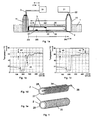
- Fig. 1 shows the principle arrangements for measuring the state of cure during sewer rehabilitation using fiber optic temperature measurement.
- a liner 2 built into the channel 1.
- the supply of heat energy 22 for the curing of the liner takes place from the supply carriage 21 via the shaft 12.
- the installation of the sensor cable 3, on the other hand, took place from the opposite shaft 11.
- the illustrated example shows a sensor arrangement in the form of a stub.
- the optical measuring signal is generated in the evaluation unit 31 (optical backscatter measuring device) and coupled into the sensor cable (optical fiber: fiber optic cable).
- the backscattered light from the optical fiber can be used in a known manner for the spatially distributed temperature measurement.
- the sensor cable is arranged so that the local temperature graph ( Fig. 1b and Fig.
- the temperature along the fiber optic cable up to approx. 150m
- the shaft area between 150m and 235m
- the temperature distribution along the sole area between 235m and 365m
- the apex area between 365m and 495m
- the permissible temperature tolerance band 43 for the curing process of the respective formulation can be implemented in the software evaluation and representation of the local temperature curves, so that irregularities can be detected, assessed and localized. Irregularities, for example due to local inflows of extraneous water 41 or local overheating 42 are in the temperature curve of the FIG. 1b respectively. Figure 1c shown.
- Figure 1d shows a sensor arrangement; in which the optical fiber sensor 3 is positioned in the horizontal direction to the liner in order to achieve a high measurement density in the longitudinal direction of the liner. At the respective end of the liner 2, the optical fiber is returned in the form of loops 36. Longitudinal arrangements of the fiber optic sensor 34 are preferably used in thermosetting liners.
- Figure 1e shows a sensor arrangement in which the optical fiber sensor 3 is positioned in the radial direction of the liner to a high measurement density in the transverse direction 35 of the liner to achieve. Transverse arrangements of the fiber optic sensor 35 are preferably used in light-curing liners.
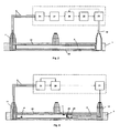
- the FIG. 2 shows a device for process control of liner cure, in combination with a fiber optic temperature measurement using a thermal model.
- the evaluation 31 calculates based on the local and temporal temperature measurement data of the fiber optic sensor (thermographic image 37 ) the current thermal resistances of the liner resin. These data, together with the (actual) supplied heat energy, are provided to a thermal model 38 for further calculation.
- the supplied heat energy can be determined, for example, (indirectly) from the process parameters 23 of the heat energy supply or (directly) by measuring the process temperature. According to the result of the thermodynamic model, the supply of the heat energy 22 is increased or decreased.
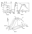
- FIG. 3 should clarify relationships with regard to statements on liner quality.
- the graphs of FIGS. 3a to 3c refer to the principle arrangement of FIG. 1a and show the temperature profile during the curing of a liner in various forms of presentation.
- the temporal. Verläute the in Fig. 3a marked location points (52, 53 and 56) are in the FIG. 3b over the entire measuring period (600 min).
- FIG. 4 refers to the problem with the sampling by means of milling robot and shows a device for positioning a milling robot. If quality defects 4 are detected on the liner, a sample is removed from the liner 2 with the aid of a milling robot 24. The positioning of the milling robot takes place, for example, from the supply carriage 21. To achieve the most accurate positioning, the milling robot has a heat source 25. By software, the removal of the temperature location of the heat source 25 from the temperature location the damage site are calculated. According to the result of a coordinate adjustment 29, the milling robot is repositioned until the exact location for the sampling is found.
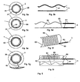
- FIGS. 5a to 5i show examples in the form of schematic representations of various arrangements and embodiments of the fiber optic sensor for use in pipe and duct systems using pipe lining method.
- the fiber optic sensor can be used as fiber optic sensor cable 61 (s. Fig. 5b ), as fiber optic sensor fiber 64 (s. Fig. 5d ) or as an optical fiber sensor 62, 63 (s. Fig. 5f and 5i ).
- the optical fiber sensor cable 61 is preferably positioned between the old pipe / channel 1 and Preliner / sliding film 26 (s. Fig. 5a
- the fiber optic sensor fiber 64 is suitable for integration into the liner 2 (s. Fig. 5c ) and the fiber optic sensor mat 62, 63 is preferably installed between the old pipe and Preliner / sliding film (s. Fig. 5e and Fig.
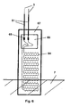
- FIG. 6 shows an example of a sensor mat design with sleeve 67 for the height measurement in the shaft area.
- the fiber optic fiber 64 is arranged meandering.
- the sensor mat includes a splice cassette 68.
- the fiber optic sensor fiber 64 is connected to a rugged fiber optic sensor cable 61 with a splice connection 65.
Landscapes
- Physics & Mathematics (AREA)
- General Physics & Mathematics (AREA)
- Engineering & Computer Science (AREA)
- General Engineering & Computer Science (AREA)
- Mechanical Engineering (AREA)
- Manufacturing & Machinery (AREA)
- Measuring Temperature Or Quantity Of Heat (AREA)
- Lining Or Joining Of Plastics Or The Like (AREA)
Claims (10)
- Procédé de surveillance de l'état thermique d'un flexible (2),• qui se trouve en tant que habillage dans un système de tuyau ou de canaux,• sachant qu'au moins un capteur à fibre optique (3) est mis en contact thermo-conducteur avec le flexible (2) pour la technologie des capteurs de température à définition locale.• et au moyen de la technologie des capteurs de température à fibre optique, à définition locale, une image thermographique (37) représentant des données de mesure de température à définition locale est créée en fonction du lieu (z) et du temps (t),
caractérisé en ce que• le flexible est imprégné de résine thermodurcissable et• l'image thermographique est créée dans le système pendant l'installation et le durcissement du flexible. - Procédé selon revendication 1, caractérisé par une mise en contact plane et en forme de méandre du capteur à fibre optique minimum (3, 64) avec le flexible (2).
- Procédé selon revendication 1, caractérisé par une mise en contact linéaire du capteur à fibre optique minimum (3, 64) avec le flexible (2).
- Procédé selon l'une des revendications précédentes, caractérisé en ce que l'image thermographique (37) est mise en corrélation avec un modèle thermique du système.
- Procédé selon l'une des revendications précédentes, caractérisé en ce que l'image thermographique (37) est mise en corrélation avec une plage de tolérance de température pouvant être fixée.
- Procédé selon l'une des revendications précédentes, caractérisé par détection de divergences locales thermiques de températures de durcissement mesurées à prognostiquer au moyen de l'image thermographique (37).
- Procédé selon revendication 6, caractérisé par réglage d'un robot (24) déplaçable dans le système sur au moins un endroit avec divergence thermique détectée par l'utilisation divergence thermique détectée.
- Procédé selon l'une des revendications précédentes, caractérisé par mise en contact du capteur à fibre optique minimum (3) sur un endroit dans le système entre le flexible à durcir (2) et un ancien tuyau.
- Procédé selon l'une des revendications 1 à 8, caractérisé par la mise en contact du capteur à fibre optique minimum (3) à l'intérieur d'un flexible renforcé par fibres de verre imprégné avec de la résine thermodurcissable.
- Procédé selon l'une des revendications précédentes, caractérisé par l'utilisation d'une technologie des capteurs de température à fibre optique sous forme de technologie des capteurs de température Raman.
Priority Applications (1)
| Application Number | Priority Date | Filing Date | Title |
|---|---|---|---|
| PL08015793T PL2037246T3 (pl) | 2007-09-07 | 2008-09-08 | Sposób monitorowania stanu rękawa na okładziny w systemie rur lub kanałów |
Applications Claiming Priority (1)
| Application Number | Priority Date | Filing Date | Title |
|---|---|---|---|
| DE102007042546A DE102007042546B4 (de) | 2007-09-07 | 2007-09-07 | Verfahren zur ortsaufgelösten Temperaturmessung in einem Rohr- oder Kanalsystem |
Publications (4)
| Publication Number | Publication Date |
|---|---|
| EP2037246A2 EP2037246A2 (fr) | 2009-03-18 |
| EP2037246A3 EP2037246A3 (fr) | 2011-05-18 |
| EP2037246B1 true EP2037246B1 (fr) | 2012-11-28 |
| EP2037246B8 EP2037246B8 (fr) | 2019-12-25 |
Family
ID=40280196
Family Applications (1)
| Application Number | Title | Priority Date | Filing Date |
|---|---|---|---|
| EP08015793.6A Active EP2037246B8 (fr) | 2007-09-07 | 2008-09-08 | Procédé destiné à la surveillance de l'état d'un tuyau pour un habillage dans un système de tuyaux ou de canaux |
Country Status (7)
| Country | Link |
|---|---|
| US (2) | US8162535B2 (fr) |
| EP (1) | EP2037246B8 (fr) |
| DE (1) | DE102007042546B4 (fr) |
| DK (1) | DK2037246T3 (fr) |
| ES (1) | ES2400245T3 (fr) |
| PL (1) | PL2037246T3 (fr) |
| PT (1) | PT2037246E (fr) |
Cited By (2)
| Publication number | Priority date | Publication date | Assignee | Title |
|---|---|---|---|---|
| WO2017101915A1 (fr) | 2015-12-18 | 2017-06-22 | Sml Verwaltungs Gmbh | Procédé permettant de faire durcir un tuyau de revêtement |
| WO2024230898A1 (fr) * | 2023-05-08 | 2024-11-14 | Relineeurope Gmbh | Revêtement tubulaire comprenant des capteurs intégrés |
Families Citing this family (27)
| Publication number | Priority date | Publication date | Assignee | Title |
|---|---|---|---|---|
| US8757870B2 (en) * | 2007-03-22 | 2014-06-24 | Baker Hughes Incorporated | Location dependent calibration for distributed temperature sensor measurements |
| EP2462758B1 (fr) * | 2009-08-04 | 2018-05-30 | Zia Systems, LLC | Système et procédé pour l'installation d'un revêtement interne |
| DE102010011610A1 (de) | 2010-03-16 | 2011-09-22 | Bkp Berolina Polyester Gmbh & Co. Kg | Optisches Sensorkabel und Verwendung des Sensorkabels während der Installation eines Relining-Schlauchs |
| US20110186203A1 (en) | 2011-04-08 | 2011-08-04 | Richard Lindner | Method and apparatus for determining proper curing of pipe liners using distributed temperature sensing |
| US20120255664A1 (en) * | 2011-04-08 | 2012-10-11 | Richard Lindner | Method and apparatus for determining proper curing of pipe liners using distributed temperature sensing |
| US9196387B2 (en) * | 2011-11-03 | 2015-11-24 | Atomic Energy Of Canada Limited | Apparatus and method for detecting position of annulus spacer between concentric tubes |
| EP2851669A1 (fr) * | 2012-06-05 | 2015-03-25 | Airbus Operations GmbH | Système et procédé de surveillance d'un composant d'avion ou de vaisseau spatial en cours de production et/ou de service |
| US9849625B2 (en) * | 2012-07-13 | 2017-12-26 | Lmk Technologies Llc | Temperature sensing within an underground structure to determine liner cure schedule |
| US8844577B2 (en) | 2012-07-30 | 2014-09-30 | Lmk Technologies, Llc | Pipe liner having a wireless data transmitter with sensing capabilities |
| CN102853937B (zh) * | 2012-09-14 | 2014-09-17 | 长沙有色冶金设计研究院有限公司 | 氧化铝熔出工艺用感温光缆测定管道系统表面多点温度的装置 |
| US10401164B2 (en) * | 2012-10-16 | 2019-09-03 | Exxonmobil Research And Engineering Company | Sensor network design and inverse modeling for reactor condition monitoring |
| DE102013001092A1 (de) * | 2013-01-23 | 2014-07-24 | Martin GmbH für Umwelt- und Energietechnik | Verfahren zum Führen einer Leitung in einer Verbrennungsanlage sowie Vorrichtung mit einer derartigen Leitung |
| WO2014143489A1 (fr) * | 2013-03-11 | 2014-09-18 | Exxonmobil Upstream Research Company | Système de surveillance de revêtement de canalisation |
| JP6315366B2 (ja) * | 2013-08-09 | 2018-04-25 | 日本発條株式会社 | コントロールケーブル用アウターケーシング及びその製造方法並びにコントロールケーブル |
| DE102014110929A1 (de) | 2014-07-31 | 2016-02-04 | Sml Verwaltungs Gmbh | Auskleidungsschlauch zur Sanierung fluidführender Leitungssysteme |
| DE102014217503A1 (de) * | 2014-09-02 | 2016-03-03 | Illinois Tool Works Inc. | Spülmaschine mit einer Flüssigkeits-Transportleitung |
| US11095101B2 (en) * | 2016-09-06 | 2021-08-17 | Quanta Associates, L.P. | Repurposing pipeline for electrical cable |
| US20180136017A1 (en) * | 2016-09-15 | 2018-05-17 | Lloyd's Register Americas, Inc. | Integration of fiber optic sensors into sleeve |
| CA3088019A1 (fr) * | 2018-10-16 | 2020-04-23 | Sanexen Services Environnementaux Inc. | Systemes et procedes de renovation de conduits d'eau et d'autres conduits |
| CN110296765A (zh) * | 2019-06-06 | 2019-10-01 | 深圳市合众清洁能源研究院 | 一种全温度场测量式特种非均匀电加热元件及制造方法 |
| WO2021030726A1 (fr) * | 2019-08-15 | 2021-02-18 | Quanta Associates, L.P. | Réadaptation de canalisations pour câbles électriques |
| EP3842776A1 (fr) * | 2019-12-27 | 2021-06-30 | Tubacex Innovación A.I.E. | Ensemble pour surveiller la température et la contrainte d'un tuyau |
| CN113532691B (zh) * | 2021-07-15 | 2024-05-28 | 威海建设集团股份有限公司 | 一种大体积混凝土温度自动采集及其降温处理系统 |
| DE102022105673A1 (de) * | 2022-03-10 | 2023-09-14 | PFW Aerospace GmbH | Verfahren zur Herstellung eines mindestens zweischichtigen Sandwichbauelements |
| CN115683457B (zh) * | 2023-01-05 | 2023-04-07 | 中国核动力研究设计院 | 微流道换热器泄漏检测方法及测量系统 |
| FR3153410A1 (fr) * | 2023-09-27 | 2025-03-28 | Airbus Operations (S.A.S.) | Dispositif de mesure de temperature a fibre optique isolee d’une paroi de fixation par une piece comprenant du liege |
| US12291944B1 (en) | 2023-10-13 | 2025-05-06 | Saudi Arabian Oil Company | System and method for deploying fiber optic cables with a cured-in-place pipe liner |
Family Cites Families (54)
| Publication number | Priority date | Publication date | Assignee | Title |
|---|---|---|---|---|
| SE435866B (sv) | 1983-04-06 | 1984-10-22 | Vj System Ab | Forfarande och anordning for infodring av rorledningar, med en flexibel, herdbar plast innehallande slang |
| JPH0477624A (ja) * | 1990-07-20 | 1992-03-11 | Sumitomo Electric Ind Ltd | 水位センサ及び水位監視方法 |
| US5124151A (en) * | 1990-08-07 | 1992-06-23 | Mediventures Inc. | Drug delivery by injection with thermo-irreversible gels |
| CA2089223C (fr) * | 1992-02-13 | 1999-06-01 | Kazuo Amano | Ouvrage de detection de temperature anormale, destine a une conduite de fluide |
| CA2168756C (fr) | 1993-08-06 | 2004-12-07 | Joachim Brandenburger | Methode et apparreil pour la fabrication d'un tuyau souple avec doublure interieure |
| DE9318404U1 (de) * | 1993-12-01 | 1994-02-10 | GESO Gesellschaft für Sensorik, geotechnischen Umweltschutz und mathematische Modellierung mbH Jena, 07743 Jena | Einrichtung zum Bestimmen von Temperaturen an und in ausgedehnten Objekten |
| ATE164004T1 (de) | 1994-07-16 | 1998-03-15 | Felten & Guilleaume Energie | Verfahren zur auswertung optisch rückgestreuter signale zur bestimmung eines streckenabhängigen messprofils eines rückstreumediums |
| CA2178076A1 (fr) | 1994-10-03 | 1996-04-11 | Arnold Harold Hartog | Surveillance des temperatures des parois propres de cuves de reacteurs |
| DE19509129C2 (de) | 1995-02-24 | 1998-07-02 | Geso Ges Fuer Sensorik Geotech | Verfahren und Vorrichtung zur Kontrolle und Überwachung des Zustandes von Rohren, Behältern, Pipelines oder dergleichen |
| US5921285A (en) * | 1995-09-28 | 1999-07-13 | Fiberspar Spoolable Products, Inc. | Composite spoolable tube |
| US5770155A (en) * | 1995-11-21 | 1998-06-23 | United Technologies Corporation | Composite structure resin cure monitoring apparatus using an optical fiber grating sensor |
| DE29623263U1 (de) * | 1996-08-06 | 1998-06-04 | Forschungszentrum Karlsruhe GmbH, 76133 Karlsruhe | Vorrichtung zum ortsaufgelösten Substanznachweis |
| US6004639A (en) * | 1997-10-10 | 1999-12-21 | Fiberspar Spoolable Products, Inc. | Composite spoolable tube with sensor |
| DE19817413C2 (de) | 1998-04-18 | 2002-09-19 | Uv Reline Tec Gmbh & Co | Verfahren und Vorrichtung zum Sanieren von Rohrleitungen |
| US6547435B1 (en) * | 1998-05-15 | 2003-04-15 | GESO Gesellschaft für Sensorik, Geotechnischen Umweltschutz und Mathematische Modellierung mbH Jena | Device for monitoring temperature distribution on the basis of distributed fiber-optic sensing, and use of same |
| GB9812465D0 (en) * | 1998-06-11 | 1998-08-05 | Abb Seatec Ltd | Pipeline monitoring systems |
| DE19826155A1 (de) * | 1998-06-12 | 2000-02-17 | Jens Bauer | Verfahren und Einrichtung zum Sanieren unbegehbarer Rohre, insbesondere Abwasserrohre |
| GB9813095D0 (en) * | 1998-06-18 | 1998-08-19 | Secr Defence | Temperature sensing apparatus |
| US6935376B1 (en) * | 1998-07-28 | 2005-08-30 | Safetyliner Systems, Llc | Enhancement of profiled tubular lining systems by channel augmentation |
| DE19844753B4 (de) * | 1998-08-03 | 2004-07-15 | AVU Aktiengesellschaft für Versorgungs-Unternehmen | Vorrichtung zum Überwachen des Zustands von Rohren, Rohrsystemen, Pipelines oder dergleichen Gas oder flüssige Medien führenden Einrichtungen und Verfahren und Einrichtung zum Verlegen einer Kabel-Verbundanordnung für die Zustandsüberwachung und Nachrichtenübermittlung |
| DE19950880C1 (de) * | 1999-10-22 | 2001-06-28 | Torsten Gogolla | Verfahren und Fasersensor zur Korrektur von im Zuge ortsausgelöster Messungen aufgenommenen Brillouin-Spektren |
| US6751342B2 (en) * | 1999-12-02 | 2004-06-15 | Thermal Wave Imaging, Inc. | System for generating thermographic images using thermographic signal reconstruction |
| DE10004384C2 (de) * | 2000-02-02 | 2003-04-03 | Daimler Chrysler Ag | Anordnung und Verfahren zur Erfassung von Dehnungen und Temperaturen und deren Veränderungen einer auf einem Träger, insbesondere einem aus Metall, Kunststoff oder Keramik bestehenden Träger, applizierten Deckschicht |
| DE20005871U1 (de) | 2000-03-30 | 2000-08-03 | UV Reline.tec GmbH & Co., 87437 Kempten | Strahlungsquelle für die Bestrahlung von Innenwänden langgestreckter Hohlräume mit eiförmigem Querschnitt |
| CA2427534A1 (fr) * | 2000-06-09 | 2001-12-20 | Fiberliner Networks | Procede et dispositif pour equiper un conduit d'une garniture interne |
| DE10122565B4 (de) | 2001-05-10 | 2010-01-14 | Allmann, Ludwig | Verfahren zum Sanieren von Rohrleitungen |
| US6803335B2 (en) * | 2001-08-03 | 2004-10-12 | The University Of Southampton | Gallium lanthanum sulfide glasses and optical waveguides and devices using such glasses |
| US6813403B2 (en) * | 2002-03-14 | 2004-11-02 | Fiber Optic Systems Technology, Inc. | Monitoring of large structures using brillouin spectrum analysis |
| EP1527306B1 (fr) | 2002-08-06 | 2011-06-01 | LIOS Technology GmbH | Four, procede et systeme de surveillance destines a surveiller l'etat de ce four |
| DE10338178A1 (de) * | 2002-08-19 | 2004-03-25 | Lammering, Martina | Verfahren zur Anordnung von Kommunikationsmitteln in rohrleitungssystemen |
| EA007244B1 (ru) * | 2003-03-05 | 2006-08-25 | Шелл Интернэшнл Рисерч Маатсхаппий Б.В. | Узел со спирально свернутыми оптическими волокнами для измерения давления и/или других физических данных |
| US7706640B2 (en) * | 2003-10-23 | 2010-04-27 | Prysmian Cavi E Sistemi Energia S.R.L. | Telecommunication optical cable for gas pipeline applications having built-in leakage detecting device |
| GB0409865D0 (en) * | 2004-05-01 | 2004-06-09 | Sensornet Ltd | Direct measurement of brillouin frequency in distributed optical sensing systems |
| NO321068B1 (no) * | 2004-05-28 | 2006-03-13 | Nexans | Umbilical-kabel |
| US20050274425A1 (en) * | 2004-06-03 | 2005-12-15 | Itt Manufacturing Enterprises, Inc. | Flexiform tubing |
| DE102004059883A1 (de) | 2004-12-10 | 2006-06-14 | Brandenburger Patentverwertung Gbr (Vertretungsberechtigte Gesellschafter Herr Joachim Brandenburger | Herstellung eines harzgetränkten Faserschlauches zur Innenauskleidung von Kanälen und Rohrleitungen |
| US7374127B2 (en) * | 2005-01-12 | 2008-05-20 | Smart Pipe Company, Inc. | Systems and methods for making pipe liners |
| US8567450B2 (en) * | 2005-01-12 | 2013-10-29 | Smart Pipe Company Lp | Methods and systems for in situ manufacture and installation of non-metallic high pressure pipe and pipe liners |
| US7585107B2 (en) * | 2006-01-17 | 2009-09-08 | Weatherford/Lamb, Inc. | Corrected DTS measurements based on Raman-Stokes signals |
| WO2007087720A1 (fr) * | 2006-02-02 | 2007-08-09 | University Of Regina | Dispositif de detection de fuites dans une canalisation |
| NO324585B1 (no) * | 2006-02-21 | 2007-11-26 | Nexans | Feildeteksjons-system |
| US7499151B2 (en) * | 2006-06-05 | 2009-03-03 | University Of Ottawa | Distributed Brillouin sensor system based on DFB lasers using offset locking |
| US7379631B2 (en) * | 2006-06-12 | 2008-05-27 | Baker Hughes Incorporated | Multi-core distributed temperature sensing fiber |
| GB0612868D0 (en) * | 2006-06-29 | 2006-08-09 | Schlumberger Holdings | Fiber optic temperature monitoring sensor for use on sub-sea pipelines to predict hydrate formation |
| US7509008B2 (en) * | 2006-10-06 | 2009-03-24 | Halliburton Energy Services, Inc. | Method and apparatus for locating a localized temperature change in a workspace |
| CA2619317C (fr) * | 2007-01-31 | 2011-03-29 | Weatherford Technology Holdings, Llc | Mesure de la temperature repartie par effet brillouin etalonnee sur place avec detection de la temperature repartie par effet raman |
| US7437046B2 (en) * | 2007-02-12 | 2008-10-14 | Furukawa Electric North America, Inc. | Optical fiber configuration for dissipating stray light |
| US20100229662A1 (en) * | 2007-04-29 | 2010-09-16 | Brower David V | Instrumentation and Monitoring System For Pipes and Conduits Transporting Cryogenic Materials |
| US8380021B2 (en) * | 2007-09-06 | 2013-02-19 | Shell Oil Company | High spatial resolution distributed temperature sensing system |
| US7941906B2 (en) * | 2007-12-31 | 2011-05-17 | Schlumberger Technology Corporation | Progressive cavity apparatus with transducer and methods of forming and use |
| US8303176B2 (en) * | 2010-05-11 | 2012-11-06 | Vladimir Kochergin | Cryogenic fiber optic temperature sensor and method of manufacturing the same |
| US8328969B2 (en) * | 2011-01-04 | 2012-12-11 | Gearhart Stephen V | Method and system for curing pipe liners using microwave energy |
| US20110186203A1 (en) * | 2011-04-08 | 2011-08-04 | Richard Lindner | Method and apparatus for determining proper curing of pipe liners using distributed temperature sensing |
| US20130034324A1 (en) * | 2011-08-03 | 2013-02-07 | Baker Hughes Incorporated | Optical fiber sensor and method for adhering an optical fiber to a substrate |
-
2007
- 2007-09-07 DE DE102007042546A patent/DE102007042546B4/de not_active Expired - Fee Related
-
2008
- 2008-09-08 ES ES08015793T patent/ES2400245T3/es active Active
- 2008-09-08 DK DK08015793.6T patent/DK2037246T3/da active
- 2008-09-08 PL PL08015793T patent/PL2037246T3/pl unknown
- 2008-09-08 PT PT80157936T patent/PT2037246E/pt unknown
- 2008-09-08 US US12/206,515 patent/US8162535B2/en active Active
- 2008-09-08 EP EP08015793.6A patent/EP2037246B8/fr active Active
-
2012
- 2012-02-23 US US13/403,393 patent/US8727614B2/en active Active
Cited By (4)
| Publication number | Priority date | Publication date | Assignee | Title |
|---|---|---|---|---|
| WO2017101915A1 (fr) | 2015-12-18 | 2017-06-22 | Sml Verwaltungs Gmbh | Procédé permettant de faire durcir un tuyau de revêtement |
| WO2017101916A1 (fr) | 2015-12-18 | 2017-06-22 | Sml Verwaltungs Gmbh | Système permettant de faire durcir un tuyau de revêtement |
| EP3389991B1 (fr) * | 2015-12-18 | 2022-06-29 | RelineEurope AG | Système permettant de faire durcir un tuyau de revêtement |
| WO2024230898A1 (fr) * | 2023-05-08 | 2024-11-14 | Relineeurope Gmbh | Revêtement tubulaire comprenant des capteurs intégrés |
Also Published As
| Publication number | Publication date |
|---|---|
| EP2037246B8 (fr) | 2019-12-25 |
| US20120147920A1 (en) | 2012-06-14 |
| US8162535B2 (en) | 2012-04-24 |
| ES2400245T3 (es) | 2013-04-08 |
| US8727614B2 (en) | 2014-05-20 |
| DE102007042546A1 (de) | 2009-03-12 |
| DE102007042546B4 (de) | 2010-01-14 |
| DK2037246T3 (da) | 2013-03-11 |
| EP2037246A3 (fr) | 2011-05-18 |
| US20090092173A1 (en) | 2009-04-09 |
| EP2037246A2 (fr) | 2009-03-18 |
| ES2400245T8 (es) | 2020-01-28 |
| PT2037246E (pt) | 2013-03-04 |
| PL2037246T3 (pl) | 2013-04-30 |
Similar Documents
| Publication | Publication Date | Title |
|---|---|---|
| EP2037246B1 (fr) | Procédé destiné à la surveillance de l'état d'un tuyau pour un habillage dans un système de tuyaux ou de canaux | |
| KR101569501B1 (ko) | 견인방향 보정 및 도통봉의 간격 유지 장치가 장착된 곡률 반경 측정 시스템 | |
| DE102014112254B4 (de) | Verfahren zur Sanierung einer Rohrleitung | |
| DE102013224977A1 (de) | Stranggießkokille mit einem Temperatursensor und Herstellungsverfahren für die Stranggießkokille mit dem Temperatursensor | |
| CN116608358B (zh) | 一种复合材料管道成型的全历程智能检测方法及应用 | |
| KR101393690B1 (ko) | 튜브 종점부 경화온도 제어기능을 구비한 관로 보수장치 및 이를 이용한 관로 비굴착 내면 전체 보수공법 | |
| EP3389991A1 (fr) | Système permettant de faire durcir un tuyau de revêtement | |
| DE102007048978A1 (de) | Verfahren zum Messen von Funktionsparametern einer Erdwärmenutzungsanordnung mittels eines faseroptischen Temperatursensorkabels | |
| DE10052922B4 (de) | Sensorkabel für faseroptische Temperturmessungen | |
| JP2008134221A (ja) | 赤外線配管診断方法、及び赤外線配管診断装置 | |
| JP6315605B2 (ja) | 構造物撮影システム | |
| WO2010052126A1 (fr) | Procédé pour mesurer la température et/ou la pression au niveau d'un pipeline, en particulier dans la zone en mer d'installations d'extraction de pétrole et de gaz | |
| DE19825500C1 (de) | Verfahren und Vorrichtung zur Messung von Fluidbewegungen mittels Lichtwellenleiter | |
| Panasiuk et al. | The concept of using the mobile robot for telemechanical wires installation in pipelines | |
| EP1197730B1 (fr) | Procédé pour déterminer des profils longitudinaux et dispositif pour mettre en oeuvre le procédé | |
| JPH0752126B2 (ja) | 地中埋設電力ケーブルの最高温度評価方法 | |
| WO2017129172A1 (fr) | Procédé et dispositif de détection par mesure d'un système de conduites | |
| DE202004013240U1 (de) | Vorrichtung zur Detektion und Markierung von Temperaturanomalien in Rohren | |
| AT413000B (de) | Verfahren zum bestimmen von längsprofilen und vorrichtung zum durchführen des verfahrens | |
| DE102005024926B4 (de) | Verfahren und Vorrichtung zum Detektieren von Infiltrationen in flüssigkeitsgefüllte Kanäle | |
| EP4339498B1 (fr) | Procédé de rénovation d'un tuyau de canalisation au moyen d'un tubage flexible | |
| KR102643338B1 (ko) | 스마트센서링을 적용하는 경량형 광경화 방식의 비굴착 관로 보수 보강 공법 | |
| DE102022110506A1 (de) | Verfahren zur Untersuchung der Wärmeverluste von Fernwärmeleitungen | |
| WO2010018357A1 (fr) | Revêtement de tuyau | |
| EP4170311B1 (fr) | Procédé et agencement de vérification d'au moins une conduite de refoulement |
Legal Events
| Date | Code | Title | Description |
|---|---|---|---|
| PUAI | Public reference made under article 153(3) epc to a published international application that has entered the european phase |
Free format text: ORIGINAL CODE: 0009012 |
|
| AK | Designated contracting states |
Kind code of ref document: A2 Designated state(s): AT BE BG CH CY CZ DE DK EE ES FI FR GB GR HR HU IE IS IT LI LT LU LV MC MT NL NO PL PT RO SE SI SK TR |
|
| AX | Request for extension of the european patent |
Extension state: AL BA MK RS |
|
| PUAL | Search report despatched |
Free format text: ORIGINAL CODE: 0009013 |
|
| AK | Designated contracting states |
Kind code of ref document: A3 Designated state(s): AT BE BG CH CY CZ DE DK EE ES FI FR GB GR HR HU IE IS IT LI LT LU LV MC MT NL NO PL PT RO SE SI SK TR |
|
| AX | Request for extension of the european patent |
Extension state: AL BA MK RS |
|
| RIC1 | Information provided on ipc code assigned before grant |
Ipc: G01K 1/14 20060101AFI20090205BHEP Ipc: G01K 11/32 20060101ALI20110411BHEP Ipc: G01M 3/00 20060101ALI20110411BHEP |
|
| 17P | Request for examination filed |
Effective date: 20111014 |
|
| AKX | Designation fees paid |
Designated state(s): AT BE BG CH CY CZ DE DK EE ES FI FR GB GR HR HU IE IS IT LI LT LU LV MC MT NL NO PL PT RO SE SI SK TR |
|
| GRAP | Despatch of communication of intention to grant a patent |
Free format text: ORIGINAL CODE: EPIDOSNIGR1 |
|
| GRAS | Grant fee paid |
Free format text: ORIGINAL CODE: EPIDOSNIGR3 |
|
| GRAP | Despatch of communication of intention to grant a patent |
Free format text: ORIGINAL CODE: EPIDOSNIGR1 |
|
| GRAC | Information related to communication of intention to grant a patent modified |
Free format text: ORIGINAL CODE: EPIDOSCIGR1 |
|
| GRAA | (expected) grant |
Free format text: ORIGINAL CODE: 0009210 |
|
| AK | Designated contracting states |
Kind code of ref document: B1 Designated state(s): AT BE BG CH CY CZ DE DK EE ES FI FR GB GR HR HU IE IS IT LI LT LU LV MC MT NL NO PL PT RO SE SI SK TR |
|
| REG | Reference to a national code |
Ref country code: GB Ref legal event code: FG4D Free format text: NOT ENGLISH |
|
| REG | Reference to a national code |
Ref country code: CH Ref legal event code: EP |
|
| REG | Reference to a national code |
Ref country code: AT Ref legal event code: REF Ref document number: 586420 Country of ref document: AT Kind code of ref document: T Effective date: 20121215 |
|
| REG | Reference to a national code |
Ref country code: IE Ref legal event code: FG4D Free format text: LANGUAGE OF EP DOCUMENT: GERMAN |
|
| REG | Reference to a national code |
Ref country code: DE Ref legal event code: R096 Ref document number: 502008008750 Country of ref document: DE Effective date: 20130124 |
|
| REG | Reference to a national code |
Ref country code: RO Ref legal event code: EPE |
|
| REG | Reference to a national code |
Ref country code: PT Ref legal event code: SC4A Free format text: AVAILABILITY OF NATIONAL TRANSLATION Effective date: 20130221 |
|
| REG | Reference to a national code |
Ref country code: DK Ref legal event code: T3 |
|
| REG | Reference to a national code |
Ref country code: SE Ref legal event code: TRGR |
|
| REG | Reference to a national code |
Ref country code: ES Ref legal event code: FG2A Ref document number: 2400245 Country of ref document: ES Kind code of ref document: T3 Effective date: 20130408 |
|
| REG | Reference to a national code |
Ref country code: NL Ref legal event code: T3 |
|
| REG | Reference to a national code |
Ref country code: LT Ref legal event code: MG4D |
|
| PG25 | Lapsed in a contracting state [announced via postgrant information from national office to epo] |
Ref country code: HR Free format text: LAPSE BECAUSE OF FAILURE TO SUBMIT A TRANSLATION OF THE DESCRIPTION OR TO PAY THE FEE WITHIN THE PRESCRIBED TIME-LIMIT Effective date: 20121128 Ref country code: NO Free format text: LAPSE BECAUSE OF FAILURE TO SUBMIT A TRANSLATION OF THE DESCRIPTION OR TO PAY THE FEE WITHIN THE PRESCRIBED TIME-LIMIT Effective date: 20130228 Ref country code: LT Free format text: LAPSE BECAUSE OF FAILURE TO SUBMIT A TRANSLATION OF THE DESCRIPTION OR TO PAY THE FEE WITHIN THE PRESCRIBED TIME-LIMIT Effective date: 20121128 |
|
| REG | Reference to a national code |
Ref country code: PL Ref legal event code: T3 |
|
| PG25 | Lapsed in a contracting state [announced via postgrant information from national office to epo] |
Ref country code: SI Free format text: LAPSE BECAUSE OF FAILURE TO SUBMIT A TRANSLATION OF THE DESCRIPTION OR TO PAY THE FEE WITHIN THE PRESCRIBED TIME-LIMIT Effective date: 20121128 Ref country code: LV Free format text: LAPSE BECAUSE OF FAILURE TO SUBMIT A TRANSLATION OF THE DESCRIPTION OR TO PAY THE FEE WITHIN THE PRESCRIBED TIME-LIMIT Effective date: 20121128 Ref country code: GR Free format text: LAPSE BECAUSE OF FAILURE TO SUBMIT A TRANSLATION OF THE DESCRIPTION OR TO PAY THE FEE WITHIN THE PRESCRIBED TIME-LIMIT Effective date: 20130301 |
|
| PG25 | Lapsed in a contracting state [announced via postgrant information from national office to epo] |
Ref country code: BG Free format text: LAPSE BECAUSE OF FAILURE TO SUBMIT A TRANSLATION OF THE DESCRIPTION OR TO PAY THE FEE WITHIN THE PRESCRIBED TIME-LIMIT Effective date: 20130228 Ref country code: SK Free format text: LAPSE BECAUSE OF FAILURE TO SUBMIT A TRANSLATION OF THE DESCRIPTION OR TO PAY THE FEE WITHIN THE PRESCRIBED TIME-LIMIT Effective date: 20121128 Ref country code: EE Free format text: LAPSE BECAUSE OF FAILURE TO SUBMIT A TRANSLATION OF THE DESCRIPTION OR TO PAY THE FEE WITHIN THE PRESCRIBED TIME-LIMIT Effective date: 20121128 |
|
| PLBE | No opposition filed within time limit |
Free format text: ORIGINAL CODE: 0009261 |
|
| 26N | No opposition filed |
Effective date: 20130829 |
|
| REG | Reference to a national code |
Ref country code: HU Ref legal event code: AG4A Ref document number: E017259 Country of ref document: HU |
|
| PG25 | Lapsed in a contracting state [announced via postgrant information from national office to epo] |
Ref country code: CY Free format text: LAPSE BECAUSE OF FAILURE TO SUBMIT A TRANSLATION OF THE DESCRIPTION OR TO PAY THE FEE WITHIN THE PRESCRIBED TIME-LIMIT Effective date: 20121128 |
|
| REG | Reference to a national code |
Ref country code: DE Ref legal event code: R097 Ref document number: 502008008750 Country of ref document: DE Effective date: 20130829 |
|
| PG25 | Lapsed in a contracting state [announced via postgrant information from national office to epo] |
Ref country code: MC Free format text: LAPSE BECAUSE OF FAILURE TO SUBMIT A TRANSLATION OF THE DESCRIPTION OR TO PAY THE FEE WITHIN THE PRESCRIBED TIME-LIMIT Effective date: 20121128 |
|
| REG | Reference to a national code |
Ref country code: IE Ref legal event code: MM4A |
|
| PG25 | Lapsed in a contracting state [announced via postgrant information from national office to epo] |
Ref country code: IE Free format text: LAPSE BECAUSE OF NON-PAYMENT OF DUE FEES Effective date: 20130908 |
|
| PG25 | Lapsed in a contracting state [announced via postgrant information from national office to epo] |
Ref country code: MT Free format text: LAPSE BECAUSE OF FAILURE TO SUBMIT A TRANSLATION OF THE DESCRIPTION OR TO PAY THE FEE WITHIN THE PRESCRIBED TIME-LIMIT Effective date: 20121128 |
|
| PG25 | Lapsed in a contracting state [announced via postgrant information from national office to epo] |
Ref country code: LU Free format text: LAPSE BECAUSE OF NON-PAYMENT OF DUE FEES Effective date: 20130908 |
|
| PG25 | Lapsed in a contracting state [announced via postgrant information from national office to epo] |
Ref country code: IS Free format text: LAPSE BECAUSE OF FAILURE TO SUBMIT A TRANSLATION OF THE DESCRIPTION OR TO PAY THE FEE WITHIN THE PRESCRIBED TIME-LIMIT Effective date: 20121128 |
|
| REG | Reference to a national code |
Ref country code: FR Ref legal event code: PLFP Year of fee payment: 9 |
|
| REG | Reference to a national code |
Ref country code: FR Ref legal event code: PLFP Year of fee payment: 10 |
|
| REG | Reference to a national code |
Ref country code: FR Ref legal event code: PLFP Year of fee payment: 11 |
|
| GRAT | Correction requested after decision to grant or after decision to maintain patent in amended form |
Free format text: ORIGINAL CODE: EPIDOSNCDEC |
|
| REG | Reference to a national code |
Ref country code: CH Ref legal event code: PK Free format text: BERICHTIGUNG B8 |
|
| PLAA | Information modified related to event that no opposition was filed |
Free format text: ORIGINAL CODE: 0009299DELT |
|
| PLBE | No opposition filed within time limit |
Free format text: ORIGINAL CODE: 0009261 |
|
| REG | Reference to a national code |
Ref country code: CH Ref legal event code: PK Free format text: BERICHTIGUNG PRIORITAET |
|
| R26N | No opposition filed (corrected) |
Effective date: 20130829 |
|
| 26N | No opposition filed |
Effective date: 20130829 |
|
| REG | Reference to a national code |
Ref country code: DE Ref legal event code: R081 Ref document number: 502008008750 Country of ref document: DE Owner name: VORTEX TECHNOLOGY GROUP, LLC, HOUSTON, US Free format text: FORMER OWNER: OSSCAD BETEILIGUNGEN GMBH, 51429 BERGISCH GLADBACH, DE Ref country code: DE Ref legal event code: R081 Ref document number: 502008008750 Country of ref document: DE Owner name: VORTEX TECHNOLOGY GROUP, LLC, HOUSTON, US Free format text: FORMER OWNER: GLOMBITZA, ULRICH, DR., 51429 BERGISCH GLADBACH, DE |
|
| REG | Reference to a national code |
Ref country code: GB Ref legal event code: 732E Free format text: REGISTERED BETWEEN 20250515 AND 20250521 |
|
| REG | Reference to a national code |
Ref country code: GB Ref legal event code: 732E Free format text: REGISTERED BETWEEN 20250522 AND 20250528 |
|
| REG | Reference to a national code |
Ref country code: NL Ref legal event code: PD Owner name: VORTEX TECHNOLOGY GROUP, LLC; US Free format text: DETAILS ASSIGNMENT: CHANGE OF OWNER(S), ASSIGNMENT; FORMER OWNER NAME: OSSCAD BETEILIGUNGEN GMBH Effective date: 20250710 |
|
| REG | Reference to a national code |
Ref country code: BE Ref legal event code: PD Owner name: VORTEX TECHNOLOGY GROUP, LLC; US Free format text: DETAILS ASSIGNMENT: CHANGE OF OWNER(S), ASSIGNMENT; FORMER OWNER NAME: OSSCAD BETEILIGUNGEN GBMH Effective date: 20250428 |
|
| REG | Reference to a national code |
Ref country code: FI Ref legal event code: PCE Owner name: VORTEX TECHNOLOGY GROUP, LLC, US |
|
| REG | Reference to a national code |
Ref country code: HU Ref legal event code: FH1C Free format text: FORMER REPRESENTATIVE(S): PINTZ ES TARSAI SZABADALMI, VEDJEGY ES JOGI IRODA KFT., HU Representative=s name: PINTZ ES TARSAI KFT., HU Ref country code: HU Ref legal event code: GB9C Owner name: VORTEX TECHNOLOGY GROUP, LLC, US Free format text: FORMER OWNER(S): GLOMBITZA, ULRICH, DE |
|
| REG | Reference to a national code |
Ref country code: CH Ref legal event code: U11 Free format text: ST27 STATUS EVENT CODE: U-0-0-U10-U11 (AS PROVIDED BY THE NATIONAL OFFICE) Effective date: 20251001 |
|
| PGFP | Annual fee paid to national office [announced via postgrant information from national office to epo] |
Ref country code: PT Payment date: 20250828 Year of fee payment: 18 Ref country code: FI Payment date: 20250929 Year of fee payment: 18 |
|
| PGFP | Annual fee paid to national office [announced via postgrant information from national office to epo] |
Ref country code: DK Payment date: 20250923 Year of fee payment: 18 Ref country code: DE Payment date: 20250919 Year of fee payment: 18 |
|
| PGFP | Annual fee paid to national office [announced via postgrant information from national office to epo] |
Ref country code: PL Payment date: 20250828 Year of fee payment: 18 Ref country code: NL Payment date: 20250918 Year of fee payment: 18 Ref country code: IT Payment date: 20250919 Year of fee payment: 18 |
|
| PGFP | Annual fee paid to national office [announced via postgrant information from national office to epo] |
Ref country code: HU Payment date: 20250922 Year of fee payment: 18 Ref country code: BE Payment date: 20250918 Year of fee payment: 18 Ref country code: GB Payment date: 20250821 Year of fee payment: 18 |
|
| PGFP | Annual fee paid to national office [announced via postgrant information from national office to epo] |
Ref country code: FR Payment date: 20250919 Year of fee payment: 18 Ref country code: AT Payment date: 20250919 Year of fee payment: 18 |
|
| PGFP | Annual fee paid to national office [announced via postgrant information from national office to epo] |
Ref country code: SE Payment date: 20250918 Year of fee payment: 18 |
|
| PGFP | Annual fee paid to national office [announced via postgrant information from national office to epo] |
Ref country code: CZ Payment date: 20250903 Year of fee payment: 18 |
|
| PGFP | Annual fee paid to national office [announced via postgrant information from national office to epo] |
Ref country code: RO Payment date: 20250901 Year of fee payment: 18 |
|
| REG | Reference to a national code |
Ref country code: AT Ref legal event code: PC Ref document number: 586420 Country of ref document: AT Kind code of ref document: T Owner name: VORTEX TECHNOLOGY GROUP, LLC, US Effective date: 20251103 |
|
| PGFP | Annual fee paid to national office [announced via postgrant information from national office to epo] |
Ref country code: TR Payment date: 20251206 Year of fee payment: 18 |
|
| PGFP | Annual fee paid to national office [announced via postgrant information from national office to epo] |
Ref country code: CH Payment date: 20251001 Year of fee payment: 18 |
|
| PGFP | Annual fee paid to national office [announced via postgrant information from national office to epo] |
Ref country code: ES Payment date: 20251028 Year of fee payment: 18 |