EP2037247B1 - Temperatursensor - Google Patents
Temperatursensor Download PDFInfo
- Publication number
- EP2037247B1 EP2037247B1 EP08015880.1A EP08015880A EP2037247B1 EP 2037247 B1 EP2037247 B1 EP 2037247B1 EP 08015880 A EP08015880 A EP 08015880A EP 2037247 B1 EP2037247 B1 EP 2037247B1
- Authority
- EP
- European Patent Office
- Prior art keywords
- housing
- temperature sensor
- resistor
- sensor
- wires
- Prior art date
- Legal status (The legal status is an assumption and is not a legal conclusion. Google has not performed a legal analysis and makes no representation as to the accuracy of the status listed.)
- Active
Links
Images
Classifications
-
- G—PHYSICS
- G01—MEASURING; TESTING
- G01K—MEASURING TEMPERATURE; MEASURING QUANTITY OF HEAT; THERMALLY-SENSITIVE ELEMENTS NOT OTHERWISE PROVIDED FOR
- G01K1/00—Details of thermometers not specially adapted for particular types of thermometer
- G01K1/16—Special arrangements for conducting heat from the object to the sensitive element
- G01K1/18—Special arrangements for conducting heat from the object to the sensitive element for reducing thermal inertia
-
- G—PHYSICS
- G01—MEASURING; TESTING
- G01K—MEASURING TEMPERATURE; MEASURING QUANTITY OF HEAT; THERMALLY-SENSITIVE ELEMENTS NOT OTHERWISE PROVIDED FOR
- G01K1/00—Details of thermometers not specially adapted for particular types of thermometer
- G01K1/08—Protective devices, e.g. casings
-
- G—PHYSICS
- G01—MEASURING; TESTING
- G01K—MEASURING TEMPERATURE; MEASURING QUANTITY OF HEAT; THERMALLY-SENSITIVE ELEMENTS NOT OTHERWISE PROVIDED FOR
- G01K13/00—Thermometers specially adapted for specific purposes
- G01K13/02—Thermometers specially adapted for specific purposes for measuring temperature of moving fluids or granular materials capable of flow
Definitions
- the present invention relates to a temperature sensor, and in particular to a temperature sensor suitable for monitoring the temperature of gas in a vehicle exhaust system.
- a typical exhaust temperature sensor comprises a temperature dependant resistor element, which is provided within a protective housing.
- the housing is mounted such that it projects into the exhaust gas flow, with the resistor being mounted at the tip of the housing projecting furthest into the exhaust.
- An indication of the temperature is obtained by monitoring the resistance of the resistor. This monitoring is facilitated by the provision of a pair of wires running within the housing to connect the resistor to external circuitry.
- the housing is filled with a filler material, typically a compacted powder.
- FR 2880685 discloses a temperature sensor for a motor vehicle that comprises a heat sensitive unit placed in a protective housing. A massive ceramic cap is inserted between the unit and the housing. The unit is connected to conducting wires which are insulated and maintained by a ceramic insulating sheath. The cap has an orifice to receive the unit, where the orifice is complimentary to an outer cover of a unit to tightly adopt the surface of the unit.
- US2007195857 discloses a temperature sensor suitable for use in a vehicle exhaust.
- the temperature sensor comprises a temperature sensing portion having a metal housing configured with at least one circular fin on a surface of the metal housing.
- a temperature sensing element is generally associated with the temperature sensing portion, wherein a potting is located within a gap formed between the temperature sensing element and the metal housing and joined with a ceramic tube for carrying a plurality of high temperature metal lead wires to and from the temperature sensing portion.
- a temperature sensor suitable for use in a vehicle exhaust, the sensor comprising: a temperature dependent resistor; a pair of connection wires facilitating connection of the resistor to the external circuitry; a housing in which the resistor is mounted and through which the wires run from the resistor to an exit point; and filler material provided within the housing to support the wires and/or resistor wherein there is a gap in the filler material across which the wires run, the gap being provided between the resistor and the exit point, characterised in that the filler material surrounds the resistor and in that the gap extends fully between the side walls of the housing.
- the gap impedes the heat flow through the filler material and thus provides thermal decoupling between the resistor and the exterior of the exhaust. This improves the level of accuracy achievable by the sensor.
- the filler material is a fine grained refractory castable material.
- This material may be hardened within the housing.
- suitable materials include phosphate bonded materials, calcium aluminates or magnesium oxysulfate bonded materials.
- phosphate bonded materials such as calcium aluminates or magnesium oxysulfate bonded materials.
- Such a material provides the necessary level of support for the connecting wires.
- conventional compacted powder filler materials will not provide sufficient support to the connecting wires in the presence of normal mechanical forces such as vibration.
- the housing may be formed from any suitable material including but not limited to stainless steel or nickel base alloys.
- the housing may have a substantially circular cross-section.
- the resistor is preferably mounted in a projecting end portion of the housing.
- the projecting end portion may also be of substantially circular cross-section but is preferably of narrower cross-section than the rest of the housing. By having a narrower cross-section heat flow between the exterior of the projecting portion and the resistor is improved.
- the sensor may be adapted to be fitted in a hole provided in an exhaust wall.
- the sensor may be provided with a suitable mounting means for retaining the sensor within the hole.
- the mounting means may comprise a flange. Alternatively other suitable forms of mounting means may be used such as clamping devices or press fitting.
- the exit point for the wires is preferably in a rear portion of the housing beyond the mounting means.
- the wires may be provided with an insulating sheath.
- an additional heat exchange element may be attached to the housing.
- the additional heat exchange element may be attached to the housing adjacent to the position where the resistor is mounted.
- the additional heat exchange element may be a plate providing a large contact surface projecting into the exhaust gas. Such a plate will enable increased heat flow form the exhaust gas to the resistor and hence improve the performance of the sensor.
- the plate may be provided with one or more surface features or ridges adapted to further increase its surface area.
- the additional heat exchange element may be formed from metal or other material with good heat conductivity.
- a temperature sensor suitable for use in a vehicle exhaust, the sensor comprising: a temperature dependent resistor; a pair of connection wires facilitating connection of the resistor to the external circuitry; a housing within which the resistor is mounted and the wires run; and a filler material provided within the housing to support the wires and/or housing wherein an additional heat exchange element is provided upon the portion of the housing within which the resistor is mounted.
- the provision of the additional heat exchange element increases the flow of heat from the exhaust gas to the resistor.
- the increased heat flow from gas to resistor provides a faster response when the exhaust gas temperature rapidly changes and higher measurement accuracy amongst other benefits thus improving the performance of the sensor.
- the sensor of the second aspect of the present invention may incorporate any or all features of the first aspect of the present invention as desired or as appropriate.
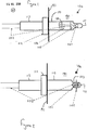
- a temperature sensor 100 projects into an exhaust pipe 190 of a vehicle through a specially provided hole (not shown) in pipe wall 191.
- the wall 191 divides a hot zone within the pipe 190 from a cold zone exterior to the pipe 190.
- the sensor 100 comprises a temperature dependent resistor 101 mounted within a protective housing 110.
- the housing 110 is formed from materials such as stainless steel, nickel base alloys or similar.
- the resistor 101 is connected to external circuitry via a pair of connecting wires 102.
- variations in temperature of the exhaust gas cause a variation in the temperature experienced by the resistor 101. Consequently, the resistance of the resistor 101 also varies.
- the resistance variation can be monitored by external circuitry via the wires 102 so as to provide an indication of the exhaust gas temperature.
- the resistor 101 is mounted in a projecting end portion 111 of the housing which is of narrower cross-section than the bulk of the housing 110. This exposes the resistor 101 more directly to the gas flow and thus improves the heat flow between the resistor 101 and the exhaust gas. The improved heat flow improves the accuracy and response time of the sensor 100.
- the housing 110 is retained in position by mounting means 112, which may comprise a flange or any other suitable means.
- mounting means 112 may comprise a flange or any other suitable means.
- the sensor may have a rear portion 113 extending beyond the mounting means 112.
- the rear portion 113 may house circuitry for monitoring the variation in resistance of the resistor 101.
- the housing 110 is filled with a filler material 103.
- the filler material 103 provides support to the resistor 101 and the wires 102.
- the filler material does not completely fill the housing 110. Instead a gap 104 is provided which is crossed by the wires 102. The gap 104 interrupts heat flow through the filler material and thus improves the thermal isolation of the resistor 101 and thereby the accuracy of the sensor 100.
- the filler material 103 is a refractory castable material such as a phosphate bonded material, a calcium aluminate or magnesium oxysulfate bonded material. Such a material provides support to the wires 102 despite the presence of the gap 104. Conventional compacted powder filler material does not provide sufficient support.
- the sensor of figure 2 may incorporate all the features of the sensor of figure 1 . Accordingly, like reference numerals have been used for like components and the description above of the general form of the sensor 100 of figure 1 , will suffice to describe the general form of the sensor 100 of figure 2 . The skilled man will of course understand that the sensor 100 of figure 2 need not incorporate all features of the sensor 100 of figure 1 .
- the sensor 100 of figure 2 may have a housing 110 substantially filled with compacted powder filler material 103, rather than the refractory castable filler material 103 having a gap 104.
- the embodiment of figure 2 is distinguished from that of figure 1 by the provision of an additional heat exchange element 105.
- the provision of the additional heat exchange element 105 improves the flow of heat from the exhaust gas to the resistor 101, thus providing a faster response when the temperature rapidly changes and higher measurement accuracy.
- the additional heat exchange element 105 shown is in the form of a simple plate but more complex elements can be used incorporating additional ridges and/or other structures to increase the surface area of the element 105 in contact with the gas.
- the heat exchange element is formed from a material having high heat conductivity, such as a metal.
Landscapes
- Physics & Mathematics (AREA)
- General Physics & Mathematics (AREA)
- Measuring Temperature Or Quantity Of Heat (AREA)
Claims (15)
- Ein Temperatursensor (100), geeignet für die Verwendung in einem Fahrzeugabgassystem, wobei der Sensor aufweist:einen temperaturabhängigen Widerstand (101);ein Paar von Anschlussdrähten (102), welche die Verbindung der Widerstände zu einer externen Schaltungsanordnung vereinfacht;ein Gehäuse (110), in welchem der Widerstand angeordnet ist und durch welches die Drähte von dem Widerstand zu einer Austrittsstelle laufen; undFüllmaterial (103), welches in dem Gehäuse zum Unterstützen der Drähte und/oder des Widerstands vorgesehen ist, wobei ein Spalt (104) in dem Füllmaterial vorgesehen ist, durch welches die Drähte verlaufen, wobei der Spalt zwischen dem Widerstand und der Austrittsstelle vorgesehen ist,dadurch gekennzeichnet,dass das Füllmaterial (103) den Widerstand (101) umgibt unddass der Spalt (104) sich vollständig zwischen den Seitenwänden des Gehäuses erstreckt.
- Temperatursensor (100) nach Anspruch 1,
dadurch gekennzeichnet,
dass das Füllmaterial (103) aus einem feinkörnigen, feuerfesten, gießbaren Material besteht, welches innerhalb des Gehäuses (110) aushärtbar ist. - Temperatursensor (100) nach einem der voranstehenden Ansprüche,
dadurch gekennzeichnet,
dass das Gehäuse (110) einen im Wesentlichen kreisförmigen Querschnitt, mit einem vorstehenden Endabschnitt (111) des Gehäuses von schmalerem im Wesentlichen kreisförmigen Querschnitt als der Rest des Gehäuses aufweist, und dass der Widerstand (101) in dem vorstehenden Endabschnitt des Gehäuses angeordnet ist. - Temperatursensor (100) nach einem der voranstehenden Ansprüche,
dadurch gekennzeichnet,
dass der Sensor angepasst ist, in einer Vertiefung einer Abgaswand angeordnet zu werden und mit einem Flansch, einer Klemmvorrichtung oder einer Presspassung zum Halten des Sensors in der Vertiefung ausgebildet ist. - Temperatursensor (100) nach einem der voranstehenden Ansprüche,
dadurch gekennzeichnet,
dass ein zusätzliches Wärmeaustauschelement (105) an dem Gehäuse gegenüberliegend zu der Position des Widerstands (101) angebracht ist. - Temperatursensor (100) nach Anspruch 5,
dadurch gekennzeichnet,
dass das zusätzliche Wärmetauschelement (105) eine große Platte ist, welche eine große Kontaktoberfläche bereitstellt, welche in die Abgase hineinragt. - Temperatursensor (100) nach Anspruch 6,
dadurch gekennzeichnet,
dass die Platte mit einem oder mehreren Oberflächen erhöhenden Merkmalen oder Rippen versehen ist, welche ausgebildet sind, weiter die Oberfläche zu erhöhen. - Temperatursensor (100) nach einem der voranstehenden Ansprüche,
dadurch gekennzeichnet,
dass ein zusätzliches Wärmetauschelement (105) auf dem Bereich des Gehäuses vorgesehen ist, an welchem innerhalb der Widerstand angeordnet ist. - Temperatursensor (100) nach Anspruch 8,
dadurch gekennzeichnet,
dass das zusätzliche Wärmetauschelement (105) eine Platte mit großer Kontaktoberfläche ist, welche in die Abgase hineinragt. - Temperatursensor (100) nach Anspruch 9,
dadurch gekennzeichnet,
dass die Platte mit einem oder mehreren weiter Oberflächen Merkmalen oder Rippen ausgebildet ist, welche ausgebildet sind, weiter die Oberfläche zu erhöhen. - Temperatursensor (100) nach einem der Ansprüche 8 oder 9,
dadurch gekennzeichnet,
dass das zusätzliche Wärmetauschelement (105) aus Metall oder einem Material gebildet ist, welches gute Wärmeleiteigenschaften aufweist. - Temperatursensor (100) nach einem der Ansprüche 8 bis 10,
dadurch gekennzeichnet,
dass das Füllmaterial (103) aus einem feinkörnigen, feuerfesten, gießbaren Material besteht, welches innerhalb des Gehäuses aushärtbar ist. - Temperatursensor (100) nach einem der Ansprüche 8 bis 11,
dadurch gekennzeichnet,
dass das Gehäuse (110) einen im Wesentlichen kreisförmigen Querschnitt, mit einem vorstehenden Endabschnitt (111) des Gehäuses von schmalerem im Wesentlichen kreisförmigen Querschnitt als der Rest des Gehäuses, aufweist und dass der Widerstand (101) in dem vorstehenden Endabschnitt (111) des Gehäuses angeordnet ist. - Temperatursensor (100) nach einem der Ansprüche 8 bis 12,
dadurch gekennzeichnet,
dass der Sensor ausgebildet ist, in einer Vertiefung einer Abgaswand angeordnet zu werden und zum Halten des Sensors in der Vertiefung mit einem Flansch, einer Klemmvorrichtung oder einer Presspassung zum Halten des Sensors in der Vertiefung ausgebildet ist. - Temperatursensor (100) nach einem der Ansprüche 8 bis 13,
dadurch gekennzeichnet,
dass der Austrittspunkt für die Drähte in einem hinteren Teil des Gehäuses (110) jenseits der Befestigungsmittel liegt.
Applications Claiming Priority (1)
| Application Number | Priority Date | Filing Date | Title |
|---|---|---|---|
| GBGB0717994.8A GB0717994D0 (en) | 2007-09-14 | 2007-09-14 | Temperature sensor |
Publications (3)
| Publication Number | Publication Date |
|---|---|
| EP2037247A2 EP2037247A2 (de) | 2009-03-18 |
| EP2037247A3 EP2037247A3 (de) | 2011-05-18 |
| EP2037247B1 true EP2037247B1 (de) | 2016-12-07 |
Family
ID=38658998
Family Applications (1)
| Application Number | Title | Priority Date | Filing Date |
|---|---|---|---|
| EP08015880.1A Active EP2037247B1 (de) | 2007-09-14 | 2008-09-09 | Temperatursensor |
Country Status (3)
| Country | Link |
|---|---|
| US (1) | US20090288481A1 (de) |
| EP (1) | EP2037247B1 (de) |
| GB (1) | GB0717994D0 (de) |
Families Citing this family (10)
| Publication number | Priority date | Publication date | Assignee | Title |
|---|---|---|---|---|
| GB0624002D0 (en) * | 2006-12-01 | 2007-01-10 | Rolls Royce Plc | Fluid temperature measurement device |
| DE102010018947B4 (de) | 2010-04-30 | 2022-11-17 | Abb Schweiz Ag | Thermischer Massendurchflussmesser mit metallgekapselter Sensorik |
| DE102010030075A1 (de) * | 2010-06-15 | 2011-12-15 | Robert Bosch Gmbh | Vorrichtung zur Erfassung einer Temperatur eines fluiden Mediums |
| DE102010030076A1 (de) * | 2010-06-15 | 2011-12-15 | Robert Bosch Gmbh | Vorrichtung zur Erfassung einer Temperatur eines strömenden fluiden Mediums |
| DE102010031127A1 (de) * | 2010-07-08 | 2012-01-12 | Endress + Hauser Flowtec Ag | Messaufnehmer eines thermischen Durchflussmessgeräts zur Ermittlung des Durchflusses eines Mediums durch ein Messrohr und Verfahren zu dessen Herstellung |
| DE102013219092B4 (de) * | 2013-09-23 | 2015-04-09 | Conti Temic Microelectronic Gmbh | Anordnung eines Temperatursensors mit einer elektrisch isolierenden Umhüllung |
| JP6459757B2 (ja) * | 2014-08-22 | 2019-01-30 | 株式会社デンソー | 温度センサの配管配置体 |
| WO2017067770A1 (de) * | 2015-10-19 | 2017-04-27 | Kriwan Industrie-Elektronik Gmbh | Messgerät zur erfassung wenigstens eines parameters eines fluids |
| JP6474342B2 (ja) * | 2015-10-28 | 2019-02-27 | 日立オートモティブシステムズ株式会社 | 物理量検出装置 |
| CA3088739A1 (en) | 2018-01-18 | 2019-07-25 | In-Situ, Inc. | Fast response temperature sensors |
Family Cites Families (17)
| Publication number | Priority date | Publication date | Assignee | Title |
|---|---|---|---|---|
| US3504544A (en) * | 1968-07-22 | 1970-04-07 | John Tymkewicz | Temperature indicating means for food preparation |
| US4560973A (en) * | 1983-11-15 | 1985-12-24 | Daimler-Benz Aktiengesellschaft | Rod shaped thermometer and method of making same |
| JPH0249129A (ja) * | 1987-09-28 | 1990-02-19 | Terumo Corp | 測温用プローブ及び該プローブを有する電子体温計 |
| JPH11218449A (ja) * | 1997-11-21 | 1999-08-10 | Denso Corp | 温度センサ及びその製造方法 |
| JP3555492B2 (ja) * | 1998-09-22 | 2004-08-18 | 株式会社デンソー | 温度センサ |
| JP4016627B2 (ja) * | 2000-11-22 | 2007-12-05 | 株式会社デンソー | 温度センサ |
| JP2002267547A (ja) * | 2001-03-14 | 2002-09-18 | Denso Corp | 温度センサ |
| JP2002289407A (ja) * | 2001-03-23 | 2002-10-04 | Denso Corp | 温度センサおよびその製造方法 |
| JP2004212269A (ja) * | 2003-01-07 | 2004-07-29 | Ngk Spark Plug Co Ltd | 温度センサ |
| US7036224B2 (en) * | 2003-05-12 | 2006-05-02 | Mamac Systems, Inc. | Method of making fluid sensor probe |
| US7740403B2 (en) * | 2004-02-09 | 2010-06-22 | Temperaturmesstechnik Geraberg Gmbh | High-temperature sensor |
| JP4620400B2 (ja) * | 2004-07-16 | 2011-01-26 | 日本特殊陶業株式会社 | 温度センサ、温度センサの製造方法 |
| FR2880685B1 (fr) * | 2005-01-12 | 2007-10-19 | Sc2N Sa | Capteur de temperature, notamment pour vehicule automobile |
| US7458718B2 (en) * | 2006-02-22 | 2008-12-02 | Honeywell International Inc. | Temperature sensor that achieves a fast response in an exhaust gas environment |
| US7303333B2 (en) * | 2006-04-21 | 2007-12-04 | Mesure Technology Co., Ltd. | Thermometer with soft flexible probe |
| DE102006034246B3 (de) * | 2006-07-21 | 2007-11-22 | Beru Ag | Temperaturfühler für ein Widerstandsthermometer, insbesondere zur Verwendung im Abgasstrang von Verbrennungsmotoren |
| JP5085398B2 (ja) * | 2007-04-16 | 2012-11-28 | 株式会社デンソー | 温度センサ |
-
2007
- 2007-09-14 GB GBGB0717994.8A patent/GB0717994D0/en not_active Ceased
-
2008
- 2008-09-09 EP EP08015880.1A patent/EP2037247B1/de active Active
- 2008-09-10 US US12/208,210 patent/US20090288481A1/en not_active Abandoned
Non-Patent Citations (1)
| Title |
|---|
| None * |
Also Published As
| Publication number | Publication date |
|---|---|
| US20090288481A1 (en) | 2009-11-26 |
| GB0717994D0 (en) | 2007-10-24 |
| EP2037247A2 (de) | 2009-03-18 |
| EP2037247A3 (de) | 2011-05-18 |
Similar Documents
| Publication | Publication Date | Title |
|---|---|---|
| EP2037247B1 (de) | Temperatursensor | |
| US7780348B2 (en) | Temperature sensor for a resistance thermometer, in particular for use in the exhaust gas system of combustion engines | |
| US7439845B2 (en) | Temperature sensor for a resistance thermometer, in particular for use in the exhaust gas system of combustion engines | |
| JP4620400B2 (ja) | 温度センサ、温度センサの製造方法 | |
| JP2000517421A (ja) | 自己検証温度センサー | |
| CN102156148B (zh) | 差示扫描热量计 | |
| US20150308875A1 (en) | Thermal Flowmeter | |
| US8197134B2 (en) | Thermocouple head unit | |
| WO2008140512A3 (en) | Exhaust gas temperature sensor with fast response | |
| CN101571428A (zh) | 多功能传感器及高温下测量热流与温度的方法 | |
| JP4274260B2 (ja) | 温度センサ | |
| US20150177073A1 (en) | High temperature measuring sensor arrangement | |
| CN102419219A (zh) | 温度传感器 | |
| US20110286494A1 (en) | Temperature sensor, manufacturing process and corresponding method of assembly | |
| CN112074715A (zh) | 具有保护管的测量插件 | |
| JP2011232343A (ja) | 流動する流体媒体の特性を検出するための装置 | |
| JP2009533587A (ja) | 内燃機関の排気系にある排気ガス触媒コンバーターの監視用装置 | |
| JP2009109313A (ja) | 圧力温度複合センサ | |
| EP0113554B1 (de) | Radial wirksame Thermoelement-Anordnung | |
| JP2007212195A (ja) | 温度センサ及びその製造方法 | |
| CN214621515U (zh) | 一种测温结构及测温针 | |
| EP1882912A2 (de) | Thermischer Gasströmungsmesser | |
| US20130133854A1 (en) | Heat exchange apparatus | |
| JP3296034B2 (ja) | サーミスタ温度センサ | |
| JP2002168700A (ja) | 温度センサ |
Legal Events
| Date | Code | Title | Description |
|---|---|---|---|
| PUAI | Public reference made under article 153(3) epc to a published international application that has entered the european phase |
Free format text: ORIGINAL CODE: 0009012 |
|
| AK | Designated contracting states |
Kind code of ref document: A2 Designated state(s): AT BE BG CH CY CZ DE DK EE ES FI FR GB GR HR HU IE IS IT LI LT LU LV MC MT NL NO PL PT RO SE SI SK TR |
|
| AX | Request for extension of the european patent |
Extension state: AL BA MK RS |
|
| PUAL | Search report despatched |
Free format text: ORIGINAL CODE: 0009013 |
|
| AK | Designated contracting states |
Kind code of ref document: A3 Designated state(s): AT BE BG CH CY CZ DE DK EE ES FI FR GB GR HR HU IE IS IT LI LT LU LV MC MT NL NO PL PT RO SE SI SK TR |
|
| AX | Request for extension of the european patent |
Extension state: AL BA MK RS |
|
| 17P | Request for examination filed |
Effective date: 20111107 |
|
| AKX | Designation fees paid |
Designated state(s): DE FR GB |
|
| 17Q | First examination report despatched |
Effective date: 20160602 |
|
| GRAP | Despatch of communication of intention to grant a patent |
Free format text: ORIGINAL CODE: EPIDOSNIGR1 |
|
| RIC1 | Information provided on ipc code assigned before grant |
Ipc: G01K 1/18 20060101ALN20160718BHEP Ipc: G01K 13/02 20060101AFI20160718BHEP Ipc: G01K 1/08 20060101ALN20160718BHEP |
|
| INTG | Intention to grant announced |
Effective date: 20160802 |
|
| GRAS | Grant fee paid |
Free format text: ORIGINAL CODE: EPIDOSNIGR3 |
|
| STAA | Information on the status of an ep patent application or granted ep patent |
Free format text: STATUS: GRANT OF PATENT IS INTENDED |
|
| GRAA | (expected) grant |
Free format text: ORIGINAL CODE: 0009210 |
|
| STAA | Information on the status of an ep patent application or granted ep patent |
Free format text: STATUS: THE PATENT HAS BEEN GRANTED |
|
| AK | Designated contracting states |
Kind code of ref document: B1 Designated state(s): DE FR GB |
|
| REG | Reference to a national code |
Ref country code: GB Ref legal event code: FG4D |
|
| REG | Reference to a national code |
Ref country code: DE Ref legal event code: R096 Ref document number: 602008047727 Country of ref document: DE |
|
| REG | Reference to a national code |
Ref country code: DE Ref legal event code: R097 Ref document number: 602008047727 Country of ref document: DE |
|
| PLBE | No opposition filed within time limit |
Free format text: ORIGINAL CODE: 0009261 |
|
| STAA | Information on the status of an ep patent application or granted ep patent |
Free format text: STATUS: NO OPPOSITION FILED WITHIN TIME LIMIT |
|
| 26N | No opposition filed |
Effective date: 20170908 |
|
| REG | Reference to a national code |
Ref country code: FR Ref legal event code: ST Effective date: 20180531 |
|
| PG25 | Lapsed in a contracting state [announced via postgrant information from national office to epo] |
Ref country code: FR Free format text: LAPSE BECAUSE OF NON-PAYMENT OF DUE FEES Effective date: 20171002 |
|
| REG | Reference to a national code |
Ref country code: DE Ref legal event code: R082 Ref document number: 602008047727 Country of ref document: DE Representative=s name: PAGE, WHITE & FARRER GERMANY LLP, DE Ref country code: DE Ref legal event code: R082 Ref document number: 602008047727 Country of ref document: DE Representative=s name: WUNDERLICH & HEIM PATENTANWAELTE PARTNERSCHAFT, DE |
|
| P01 | Opt-out of the competence of the unified patent court (upc) registered |
Effective date: 20230708 |
|
| REG | Reference to a national code |
Ref country code: GB Ref legal event code: 732E Free format text: REGISTERED BETWEEN 20241010 AND 20241016 |
|
| REG | Reference to a national code |
Ref country code: DE Ref legal event code: R082 Ref document number: 602008047727 Country of ref document: DE Representative=s name: PAGE, WHITE & FARRER GERMANY LLP, DE Ref country code: DE Ref legal event code: R081 Ref document number: 602008047727 Country of ref document: DE Owner name: SENSATA TECHNOLOGIES HOLLAND BV, NL Free format text: FORMER OWNER: EPIQ SENSOR-NITE N.V., TESSENDERLO, BE |
|
| PGFP | Annual fee paid to national office [announced via postgrant information from national office to epo] |
Ref country code: DE Payment date: 20250929 Year of fee payment: 18 |
|
| PGFP | Annual fee paid to national office [announced via postgrant information from national office to epo] |
Ref country code: GB Payment date: 20250929 Year of fee payment: 18 |