EP2037371A2 - Protocole commun et schéma de routage pour réseaux de traitement de données d'espace - Google Patents
Protocole commun et schéma de routage pour réseaux de traitement de données d'espace Download PDFInfo
- Publication number
- EP2037371A2 EP2037371A2 EP08161955A EP08161955A EP2037371A2 EP 2037371 A2 EP2037371 A2 EP 2037371A2 EP 08161955 A EP08161955 A EP 08161955A EP 08161955 A EP08161955 A EP 08161955A EP 2037371 A2 EP2037371 A2 EP 2037371A2
- Authority
- EP
- European Patent Office
- Prior art keywords
- endpoint
- layer
- switch
- protocol
- input
- Prior art date
- Legal status (The legal status is an assumption and is not a legal conclusion. Google has not performed a legal analysis and makes no representation as to the accuracy of the status listed.)
- Granted
Links
Images


Classifications
-
- G—PHYSICS
- G06—COMPUTING OR CALCULATING; COUNTING
- G06F—ELECTRIC DIGITAL DATA PROCESSING
- G06F13/00—Interconnection of, or transfer of information or other signals between, memories, input/output devices or central processing units
- G06F13/38—Information transfer, e.g. on bus
- G06F13/382—Information transfer, e.g. on bus using universal interface adapter
- G06F13/385—Information transfer, e.g. on bus using universal interface adapter for adaptation of a particular data processing system to different peripheral devices
-
- H—ELECTRICITY
- H04—ELECTRIC COMMUNICATION TECHNIQUE
- H04L—TRANSMISSION OF DIGITAL INFORMATION, e.g. TELEGRAPHIC COMMUNICATION
- H04L67/00—Network arrangements or protocols for supporting network services or applications
- H04L67/01—Protocols
- H04L67/12—Protocols specially adapted for proprietary or special-purpose networking environments, e.g. medical networks, sensor networks, networks in vehicles or remote metering networks
-
- H—ELECTRICITY
- H04—ELECTRIC COMMUNICATION TECHNIQUE
- H04L—TRANSMISSION OF DIGITAL INFORMATION, e.g. TELEGRAPHIC COMMUNICATION
- H04L69/00—Network arrangements, protocols or services independent of the application payload and not provided for in the other groups of this subclass
- H04L69/18—Multiprotocol handlers, e.g. single devices capable of handling multiple protocols
Definitions
- each data processing architecture is highly specialized and often relies upon a separate system interconnect technology. Since each customer has different system-level performance requirements, each system interconnect design starts from scratch. There is high risk associated with adopting new technology for each and every mission, and network technology is vulnerable to obsolescence since support for a given protocol may die out, leaving no path to higher performance as technology scales. Furthermore, only one protocol type may run over each physical network fabric, implying that complex space systems often require separate physical networks for separate functions such as data traffic, control, and management. The requirement of separate physical networks for each function further increases system complexity, size, weight, and power.
- a method of communicatively coupling network elements supporting multiple network protocol types comprises receiving input having multiple network protocol types from an upper-level of the protocol stack at an endpoint-flexible-interface layer in a network endpoint, mapping the input between the upper-level of a protocol stack and a common-lower-level in the protocol stack at the endpoint-flexible-interface layer, and implementing the common-lower-level protocol layer to interface the multiple network protocol types to the physical layer, so that at least two endpoints of a network are communicatively coupled.
- Figure 1 is a block diagram of one embodiment of protocol stacks in communicatively coupled network endpoints in accordance with the present invention.
- FIGS 2A and 2B are block diagrams of embodiments of protocol stacks communicatively coupling endpoints and switches in accordance with the present invention.
- FIG. 3 is a block diagram of one embodiment of an endpoint protocol stack in accordance with the present invention.
- FIG. 4 is a block diagram of one embodiment of a switch protocol stack in accordance with the present invention.
- Figure 5 is a flow diagram of one embodiment of a method to communicatively couple network elements supporting multiple network protocol types.
- Figure 6 is a flow diagram of one embodiment of a method to implement a common-lower-level protocol layer in a switch protocol stack in accordance with the present invention.
- Figure 7 is a flow diagram of one embodiment of a method to implement a common-lower-level protocol layer in an endpoint protocol stack in accordance with the present invention.
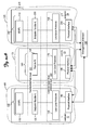
- FIG. 1 is a block diagram of one embodiment of protocol stacks 100 and 200 in respective communicatively coupled network endpoints 10 and 20 in accordance with the present invention.
- the network endpoints 10 and 20 are also referred to herein as “endpoints 10 and 20.”
- a data processing architecture for space applications is shown in a space processing system 40 housed in a spacecraft vehicle 50.
- the space processing system 40 is referred to herein as "network 40.”
- the space processing system 40 includes a plurality of network elements 10 and 20, also referred to herein as "first endpoint 10 and second endpoint 20.”
- the first endpoint 10 and second endpoint 20 are communicatively coupled to each other via the respective physical interfaces 140 and 240 of the physical layer.
- the physical interfaces 140 and 240 comprise a plurality of physical interconnections for receiving and/or transmitting inputs having a respective plurality of protocols.
- input and/or inputs
- inputs are used to represent datum, data, signals, and/or information indicative of data and/or signals that are received at layers of the protocol stacks and that are sent from the layers of the protocol stack.
- input generically represents input signals and output signals.
- a management processor 190 manages the network elements 10 and 20 in the space processing system 40.
- the management processor 190 is communicatively coupled to the first endpoint 10 and the second endpoint 20 via the respective physical interfaces 140 and 240 in order to manage them.
- the management processor 190 is one of the endpoints in the space processing system 40.
- the protocol stacks 100 and 200 in the respective network endpoints 10 and 20 each include a plurality of lower-level interconnect protocols 330 (also referred to herein as "common-lower-level protocol layer 330"), a plurality of upper-level network protocols 310 (also referred to herein as upper-level 310 of a network protocol stack), and a flexible interface layer 320 that lies between the plurality of lower-level interconnect protocols and the plurality of upper-level network protocols.
- Each upper-level network protocol is associated with a respective type of data traffic.
- the protocol stack 100 of the first endpoint 10 includes the upper-level network protocol layer (ULNPL) 110, such as an application layer, in the upper-level 310 of the network protocol stack 100, the endpoint-flexible-interface layer (Endpoint-Flexible IL) 120 in the flexible interface layer 320, and the low-level protocol 130 in the common-lower-level protocol layer 330.
- the protocol stack 200 of the second endpoint 20 includes the upper-level network protocol layer 210 in the upper-level 310 of the network protocol stack 200, the endpoint-flexible-interface layer 220 in the flexible interface layer 320, and the low-level protocol 230 in the common-lower-level protocol layer 330.
- the low-level protocol 130 is a low-level serial protocol 130.
- the lower-level interconnect protocols such as low-level protocols 130 and 230, are common to each of the plurality of network elements in the space processing system 40.
- the low-level protocols 130 and 230 include the same protocols.
- the common-lower-level protocol layer 330 provides the platform on which the plurality of upper-level network protocols co-exist.
- the flexible interface layer maps the plurality of upper level protocols in the flexible interface layer 320 to an associated one of the plurality of lower-level interconnect protocols in the common-lower-level protocol layer 330 of a network element, such as first and second endpoints 10 and 20.
- the lower-level protocols are independent of the physical transport medium and the upper-layer protocols.
- all the network elements are network endpoints.
- the network elements in the space processing system 40 comprise a tightly coupled embedded system.
- the network elements are in a processing system that is not a space processing system in a spacecraft vehicle 50.
- the network elements comprise a tightly coupled embedded system that is not a space processing system.
- Figures 2A and 2B are block diagrams of embodiments of protocol stacks communicatively coupling endpoints and switches in accordance with the present invention.
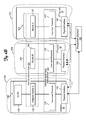
- Figure 2A is a block diagram of one embodiment of protocol stacks 100 and 200 in respective network endpoints 10 and 20 communicatively coupled via a protocol stack 300 in a switch 30 in accordance with the present invention.
- a first portion of the network elements represented generally by the numeral 105 include network endpoints, such as network endpoints 10 and 20, which each have an endpoint-flexible-interface layer 120 and 220, respectively, in the flexible interface layer 321.
- a second portion of the network elements represented generally by the numeral 106 includes switches, such as switch 30.
- Each switch 30 has a flexible-routing layer (Flexible RL) 160 in the flexible interface layer 321.
- the network elements 10 and 20 and the switch 30 are in a space processing system in a spacecraft vehicle 50.
- the management processor 190 manages the network elements, such as network endpoints 10 and 20 and the switch 30.
- the management processor 190 is communicatively coupled to the physical interfaces 140, 180, and 240 of the first endpoint 10, the switch 30, and the second endpoint 20 in order to manage them.
- the management processor 190 is communicatively coupled to the physical interface 180 of the switch 30, and the management processor 190 indirectly manages the first endpoint 10 and the second endpoint 20 via the switch 30.
- the protocol stack 300 of the switch 30 includes the flexible routing layer 160 in the flexible interface layer 321 and the low-level protocol 170 in the common-lower-level protocol layer 331.
- the protocol stacks 100 and 200 in the respective network endpoints 10 and 20 are as described above with reference to Figure 1 .
- the protocol stacks 100 and 200 of the respective first endpoint 10 and second endpoint 20 include the endpoint-flexible-interface layers 120 and 220 in the flexible interface layer 321 and the low-level protocol 130 and 230 in the common-lower-level protocol layer 331.
- the low-level protocols 130 and 230 have at least one protocol in common with the low-level protocols 170 in the switch 30, however low-level protocols 130 and 230 do not need to have any protocols in common with each other.
- the common-lower-level protocol layer 331 provides the platform on which the plurality of upper-level network protocols co-exist. In one implementation of this embodiment, a single standard lower-level protocol is run on the common-lower-level protocol layer of each protocol stack when the system is powered-on.
- the flexible routing layer 160 in the switch 30 routes the input from the first endpoint 10 to the second endpoint 20.
- the flexible routing layer 160 in the switch 30 maps the received input to the second endpoint and, based on the mapping, the switch 30 sends the input via the physical interface 180.
- the physical interface 180 comprises at least one physical interconnection for receiving and/or transmitting inputs in a respective plurality of protocols. In one implementation of this embodiment, the same physical interconnection is used for multiple upper-level protocols. In another implementation of this embodiment, the same physical interconnections are also used for some lower-level protocols. In yet another implementation of this embodiment, some lower-level protocols use different physical interconnections from the other lower-level protocols.
- Figure 2B is a block diagram of one embodiment of protocol stack 100 in respective network endpoint 10 communicatively coupled to a second switch 32 via a protocol stack 300 in a first switch 30 in accordance with the present invention.
- Figure 2B differs from Figure 2A in that the endpoint 10 is communicatively coupled to a second switch 32 via the switch 30, also referred to as first switch 30.
- the second switch 32 is similar in structure to the first switch 30 described above with reference to Figure 2A .
- the low-level protocol 172 in the common-lower-level protocol layer 331 of the second switch 32 is similar to the low-level protocol 170 in the common-lower-level protocol layer 331 of the first switch 30.
- the flexible-routing layer 162 in the second switch 32 is similar to the flexible-routing layer 160 in the first switch 30.
- the input sent to the second switch 32 is sent to yet another network element, such as a third switch or a second endpoint.
- the input sent to the second switch 32 is stored or implemented at the second switch 32 and is not sent to any other network element.
- the management processor 190 manages the network elements, such as network endpoint 10 and the switches 30 and 32.
- the management processor 190 is communicatively coupled to the physical interfaces 140, 180, and 182 of the respective endpoint 10, the first switch 30, and the second switch 32 in order to directly manage the endpoint 10, the first switch 30, and the second switch 32.
- the management processor 190 is communicatively coupled to the physical interface 180 of the first switch 30, and the management processor 190 indirectly manages the endpoint 10 and the second switch 32 via the first switch 30.
- two switches are communicatively coupled to each other via a third switch.
- FIG. 3 is a block diagram of one embodiment of an endpoint protocol stack 101 in accordance with the present invention.
- the physical interface is an electrical interface 141.
- the upper level 310 of the protocol stack includes applications using commercially available network protocols RapidIO 111, Gigibit Ethernet (GigE) 112, SpaceWire 113, and InfiniBand Architecture (IBA) 114.
- the common-lower-level protocol layer 331 of Figure 3 includes commercially available protocols including Interlaken 131 and System Packet Interface-Scalable (SPI-S) 132.
- FIG 4 is a block diagram of one embodiment of a switch protocol stack 301 in accordance with the present invention.
- the physical interface is an electrical interface 181.
- the common-lower-level protocol layer 331 of Figure 3 includes commercially available protocols including Interlaken 131 and SPI-S 132 so the switch protocol stack 301 is compatible with the endpoint protocol stack 101 as shown in Figure 3 .
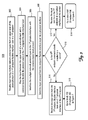
- Figure 5 is a flow diagram of one embodiment of a method 500 to communicatively couple network elements supporting multiple network protocol types.
- the method 500 is described with reference to the exemplary protocol stacks 100, 200, and 300 of Figures 1 and 2 although it is to be understood that method 500 can be implemented using other embodiments of the communicatively coupled protocol stacks as is understandable by one skilled in the art who reads this document.
- a network endpoint receives input having multiple network protocol types from an upper-level of the protocol stack at an endpoint-flexible-interface layer in the network endpoint.
- input having multiple network protocol types includes one or more inputs having multiple network protocol types.
- an endpoint-flexible-interface layer 120 in the network endpoint 10 receives input having multiple network protocol types from an upper-level network protocol layer 110 of the protocol stack 100.
- the network endpoint 10 receives input from applications that support RapidIO 111, Gigibit Ethernet (GigE) 112, SpaceWire 113, and InfiniBand Architecture (IBA) 114 ( Figure 3 ).
- RapidIO 111 Gigibit Ethernet
- IBA InfiniBand Architecture
- the endpoint-flexible-interface layer in the network endpoint maps the input between the upper-level of the protocol stack and a common-lower-level in the protocol stack.
- the endpoint-flexible-interface layer 120 in the first network endpoint 10 maps the input between the upper-level 310 of the protocol stack 100 and a common-lower-level 331 ( Figure 2A ) in the protocol stack 100.
- the multiple network protocol types are interfaced to the physical interface in the physical layer with the common-lower-level protocol layer so that at least two endpoints of the network are communicatively coupled.
- the common-lower-level protocol layer 331 is implemented to interface the multiple network protocol types to the physical interface 140 of the first network endpoint 10 so that the first network endpoint 10 is communicatively coupled to the second network endpoint 20.
- the input received from the endpoint-flexible-interface layer is sent from the network element via the first physical interface.
- the input received from the endpoint-flexible-interface layer 120 is sent from the first network element 10 via the physical interface 140.
- the management processor 190 of Figures 1 or 2 sends instructions to communicatively couple the first endpoint 10 to the second endpoint 20.
- the management processor 190 knows if the network endpoint is communicatively coupled to a switch. If the network endpoint is communicatively coupled to a switch, the flow proceeds to block 512.
- the input sent from the first endpoint is received at the physical interface of the switch in the physical layer. In one implementation of this embodiment, the input sent from the first endpoint 100 is received at the physical interface 180 of the switch 30 ( Figure 2A ).
- the flow of method 500 is directed to block 602 of method 600 in Figure 6 .
- the flow proceeds to block 516 from block 510.
- the input sent from the first endpoint flexible interface layer is received at a second physical interface in the physical layer of the second endpoint.
- the input sent from the first endpoint flexible interface layer 120 via the physical interface 140 is received at a second physical interface 240 of the second endpoint 20 ( Figure 1 ).
- the flow of method 500 is directed to block 702 of method 700 in Figure 7 .
- the protocol stack in the switch is the protocol stack shown in Figure 4 .
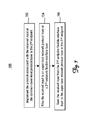
- Figure 6 is a flow diagram of one embodiment of a method 600 to implement a common-lower-level protocol layer in a switch protocol stack in accordance with the present invention.
- Method 600 is implemented when the first endpoint is communicatively coupled to the switch and after input is received at the switch from the first endpoint.
- the method 600 is described with reference to the exemplary protocol stacks 100, 200, and 300 of Figure 2A , although it is to be understood that method 600 can be implemented using other embodiments of the communicatively coupled network endpoints and switches as is understandable by one skilled in the art who reads this document.
- the switch receives input from the physical interface at the common-lower-level protocol layer.
- the switch 30 (also referred to herein as first switch 30) receives input from the physical interface 180 at the low-level protocol 170 of the common-lower-level protocol layer 331.
- the switch implements the routing requirements and functionality of the protocol of the received input at the flexible routing layer.
- the first switch 30 implements the routing requirements and functionality of the protocol of the received input at the flexible routing layer 160.
- the switch maps the received input to another network element, such as a second endpoint or a second switch, at a flexible-routing layer of the switch.
- the first switch 30 maps the received input to a second endpoint 20 at a flexible-routing layer 160 of the flexible interface layer 321.
- the first switch 30 maps the received input to a second switch 32 at a flexible-routing layer 160 of the flexible interface layer 321.
- the switch routes the input via the lower-level of the protocol stack based on the mapping at the flexible-routing layer by sending the input from a physical interface of the switch.
- the first switch 30 routes the input via the low-level protocol 170 in the common-lower-level protocol layer 331 based on the mapping at the flexible-routing layer 160 and sends the input from a physical interface 180 of the first switch 30.
- the input is routed to the second endpoint 20.
- the input is routed to the second switch 32. It is to be appreciated that the switch can route input received from the second endpoint 20 (or the second switch 32 as shown in Figure 2B ) to the first endpoint 10, since communication between the network elements is bidirectional. Thus, in other embodiments, the functionality of the first endpoint and the second endpoint are switched.
- the second endpoint receives the input sent from the switch at a second physical interface.
- the second endpoint 20 receives the input sent from the first switch 30 at a second physical interface 240.
- the flow proceeds to block 702 of method 700 in Figure 7 .
- Figure 7 is a flow diagram of one embodiment of a method 700 to implement a common-lower-level protocol layer 331 in an endpoint protocol stack 200 accordance with the present invention.
- Method 700 is implemented when input is received at the second endpoint from either a communicatively coupled first endpoint or a communicatively coupled switch in a system, such as space processing system 40 ( Figure 1 ).
- the method 700 is described with reference to the exemplary protocol stacks 100, 200, and 300 of Figures 1 and 2A although it is to be understood that method 700 can be implemented using other embodiments of the communicatively coupled protocol stacks as is understandable by one skilled in the art who reads this document.
- the second endpoint implements the protocol associated with the received input at the common-lower-level protocol.
- the second endpoint has received the input either directly from the first endpoint (see block 516 of method 500 in Figure 5 ) or indirectly from the first endpoint via the switch (see block 610 of method 600 in Figure 6 ).
- the second endpoint 20 implements the protocol associated with the received input at the low-level protocol 230 of the common-lower-level protocol 331.
- the second endpoint maps the received input to an upper-level network protocol layer at a second endpoint-flexible-interface layer.
- the second endpoint-flexible-interface layer 220 in the second endpoint 20 maps the received input to an upper-level network protocol layer 210. Based on the mapping at the second endpoint-flexible-interface layer, at block 706, the second endpoint sends the received input from the second endpoint-flexible-interface layer to the upper-level network protocol layer in the second endpoint. In one implementation of this embodiment, the second endpoint 20 sends the received input from the second endpoint-flexible-interface layer 220 to the upper-level network protocol layer 210 in the second endpoint 20. In one implementation of this embodiment, the protocol stack in the second endpoint is the protocol stack shown in Figure 3 .
- An implementation of methods 500, 600 and/or 700 provides a method of sending and/or receiving a mixture of upper-level protocol types from at least one endpoint in the network. Additionally, an implementation of methods 500, 600 and/or 700 provides a method of sending and/or receiving a mixture of upper-level protocol types from at least one switch in the network.
- a "sending and/or receiving a mixture of upper-level protocol types" includes sending and/or receiving different types of upper-level protocols in a relatively short time frame.
- a network element in an exemplary network having the architecture described in this document can send data in RapidIO format followed by data in SpaceWire format, followed by data in Gigibit Ethernet format, followed by data in SpaceWire format. Effectively, multiple protocol types can run nearly simultaneously over the flexible network using a single internconnect for sending and receiving data, control signals and management signals.
Landscapes
- Engineering & Computer Science (AREA)
- Theoretical Computer Science (AREA)
- Computer Networks & Wireless Communication (AREA)
- Signal Processing (AREA)
- General Health & Medical Sciences (AREA)
- Computing Systems (AREA)
- Health & Medical Sciences (AREA)
- Medical Informatics (AREA)
- Physics & Mathematics (AREA)
- General Engineering & Computer Science (AREA)
- General Physics & Mathematics (AREA)
- Computer Security & Cryptography (AREA)
- Communication Control (AREA)
- Data Exchanges In Wide-Area Networks (AREA)
Applications Claiming Priority (1)
| Application Number | Priority Date | Filing Date | Title |
|---|---|---|---|
| US11/838,013 US7720099B2 (en) | 2007-08-13 | 2007-08-13 | Common protocol and routing scheme for space data processing networks |
Publications (3)
| Publication Number | Publication Date |
|---|---|
| EP2037371A2 true EP2037371A2 (fr) | 2009-03-18 |
| EP2037371A3 EP2037371A3 (fr) | 2009-08-12 |
| EP2037371B1 EP2037371B1 (fr) | 2012-01-25 |
Family
ID=40262709
Family Applications (1)
| Application Number | Title | Priority Date | Filing Date |
|---|---|---|---|
| EP08161955A Ceased EP2037371B1 (fr) | 2007-08-13 | 2008-08-06 | Protocole commun et schéma de routage pour réseaux de traitement de données d'espace |
Country Status (3)
| Country | Link |
|---|---|
| US (1) | US7720099B2 (fr) |
| EP (1) | EP2037371B1 (fr) |
| JP (1) | JP2009049999A (fr) |
Cited By (1)
| Publication number | Priority date | Publication date | Assignee | Title |
|---|---|---|---|---|
| JP2016100874A (ja) * | 2014-11-26 | 2016-05-30 | Necスペーステクノロジー株式会社 | ルーティングテーブル設定装置、及び、ルーティングテーブル設定方法 |
Families Citing this family (2)
| Publication number | Priority date | Publication date | Assignee | Title |
|---|---|---|---|---|
| US20120065813A1 (en) * | 2010-09-14 | 2012-03-15 | Nguyen Quang H | System and method for command and data handling in space flight electronics |
| US10320712B2 (en) | 2017-08-17 | 2019-06-11 | The Boeing Company | System and method for configuring a switch matrix on-board a vehicle based on network information |
Citations (2)
| Publication number | Priority date | Publication date | Assignee | Title |
|---|---|---|---|---|
| WO2001043456A1 (fr) | 1999-12-07 | 2001-06-14 | Telefonaktiebolaget Lm Ericsson (Publ) | Integration de reseaux de systemes de signalisation numero 7 (ss7) avec des reseaux utilisant la commutation par etiquette multi-protocole (mpls) |
| EP1484897A1 (fr) | 2003-06-04 | 2004-12-08 | Samsung Electronics Co., Ltd. | Procédé et dispositif pour l'émission et la réception de trames de données multiprotocoles |
Family Cites Families (30)
| Publication number | Priority date | Publication date | Assignee | Title |
|---|---|---|---|---|
| JPH03178245A (ja) * | 1989-12-07 | 1991-08-02 | Nippon Telegr & Teleph Corp <Ntt> | プロトコル処理方式 |
| JPH0563749A (ja) * | 1991-09-02 | 1993-03-12 | Hitachi Ltd | マルチプロトコル通信制御装置 |
| JP3255238B2 (ja) * | 1992-06-25 | 2002-02-12 | 日本電信電話株式会社 | 通信制御処理装置 |
| US5446736A (en) * | 1993-10-07 | 1995-08-29 | Ast Research, Inc. | Method and apparatus for connecting a node to a wireless network using a standard protocol |
| JP2716028B2 (ja) * | 1995-12-26 | 1998-02-18 | 日本電気株式会社 | プロトコル変換装置 |
| US20040194101A1 (en) * | 1997-08-21 | 2004-09-30 | Glanzer David A. | Flexible function blocks |
| US6226680B1 (en) * | 1997-10-14 | 2001-05-01 | Alacritech, Inc. | Intelligent network interface system method for protocol processing |
| US7174393B2 (en) * | 2000-12-26 | 2007-02-06 | Alacritech, Inc. | TCP/IP offload network interface device |
| US6427173B1 (en) * | 1997-10-14 | 2002-07-30 | Alacritech, Inc. | Intelligent network interfaced device and system for accelerated communication |
| US6353594B1 (en) * | 1998-03-04 | 2002-03-05 | Alcatel Canada Inc. | Semi-permanent virtual paths for carrying virtual channels |
| US6331986B1 (en) * | 1998-04-24 | 2001-12-18 | Lucent Technologies Inc. | Method for resource allocation and routing in multi-service virtual private networks |
| JP2000035930A (ja) * | 1998-07-17 | 2000-02-02 | Ricoh Co Ltd | ネットワークシステム |
| US20020097725A1 (en) * | 1998-07-27 | 2002-07-25 | Nec Corporation | Resource and protocol management for virtual private networks within multiprocessor ATM switches |
| US7212543B1 (en) * | 1998-10-12 | 2007-05-01 | Teliasonera Ab | Method, system and device for establishing communication between different communication networks |
| JP3622607B2 (ja) * | 1999-11-30 | 2005-02-23 | オムロン株式会社 | 管理局及びノード並びに通信方法 |
| US7197546B1 (en) * | 2000-03-07 | 2007-03-27 | Lucent Technologies Inc. | Inter-domain network management system for multi-layer networks |
| EP1346516A4 (fr) * | 2000-11-30 | 2007-03-07 | George P Mattathil | Reseau dynamique prive |
| US7068666B2 (en) * | 2001-04-27 | 2006-06-27 | The Boeing Company | Method and system for virtual addressing in a communications network |
| JP2002368861A (ja) * | 2001-06-06 | 2002-12-20 | Casio Comput Co Ltd | 携帯電話装置 |
| JP4460195B2 (ja) * | 2001-08-06 | 2010-05-12 | 株式会社日立製作所 | パケット転送装置およびルーティング制御装置 |
| EP1522174B1 (fr) * | 2002-07-16 | 2009-09-09 | Enterasys Networks, Inc. | Appareil et procede pour un reseau local hierarchique |
| FR2854703B1 (fr) * | 2003-05-07 | 2005-06-24 | Arteris | Dispositif d'emulation d'une ou plusieurs puces de circuits integres |
| US20040264503A1 (en) * | 2003-06-30 | 2004-12-30 | Microsoft Corporation | Method and system for providing a virtual protocol interlayer |
| US7792933B2 (en) * | 2003-07-03 | 2010-09-07 | Cadence Design Systems, Inc. | System and method for performing design verification |
| FR2857114B1 (fr) | 2003-07-04 | 2005-09-30 | Arteris | Systeme et procede de communication entre des modules |
| JP2005072759A (ja) * | 2003-08-21 | 2005-03-17 | Sony Corp | 送信装置および方法、受信装置および方法、通信装置および方法、並びにプログラム |
| JP4443880B2 (ja) * | 2003-09-05 | 2010-03-31 | 株式会社エヌ・ティ・ティ・ドコモ | ノード装置及びその装置における階層間制御情報交換方法 |
| US8249082B2 (en) * | 2004-04-05 | 2012-08-21 | Verizon Business Global Llc | System method for a communications access network |
| US8891519B2 (en) * | 2004-04-05 | 2014-11-18 | Verizon Patent And Licensing Inc. | System and method for monitoring, controlling and provisioning a telecommunications access network |
| US20060203747A1 (en) * | 2005-03-11 | 2006-09-14 | Nortel Networks Limited | Network topology systems and methods |
-
2007
- 2007-08-13 US US11/838,013 patent/US7720099B2/en active Active
-
2008
- 2008-08-06 EP EP08161955A patent/EP2037371B1/fr not_active Ceased
- 2008-08-12 JP JP2008207815A patent/JP2009049999A/ja active Pending
Patent Citations (2)
| Publication number | Priority date | Publication date | Assignee | Title |
|---|---|---|---|---|
| WO2001043456A1 (fr) | 1999-12-07 | 2001-06-14 | Telefonaktiebolaget Lm Ericsson (Publ) | Integration de reseaux de systemes de signalisation numero 7 (ss7) avec des reseaux utilisant la commutation par etiquette multi-protocole (mpls) |
| EP1484897A1 (fr) | 2003-06-04 | 2004-12-08 | Samsung Electronics Co., Ltd. | Procédé et dispositif pour l'émission et la réception de trames de données multiprotocoles |
Cited By (1)
| Publication number | Priority date | Publication date | Assignee | Title |
|---|---|---|---|---|
| JP2016100874A (ja) * | 2014-11-26 | 2016-05-30 | Necスペーステクノロジー株式会社 | ルーティングテーブル設定装置、及び、ルーティングテーブル設定方法 |
Also Published As
| Publication number | Publication date |
|---|---|
| US7720099B2 (en) | 2010-05-18 |
| JP2009049999A (ja) | 2009-03-05 |
| EP2037371B1 (fr) | 2012-01-25 |
| US20090046709A1 (en) | 2009-02-19 |
| EP2037371A3 (fr) | 2009-08-12 |
Similar Documents
| Publication | Publication Date | Title |
|---|---|---|
| US6693901B1 (en) | Backplane configuration without common switch fabric | |
| EP1591908A1 (fr) | Triage de transactions entre différente canaux virtuels | |
| EP1457993A3 (fr) | Architecture de mémoire à accès multiple, dispositifs et systèmes incluant cette dernière, et procédé d'utilisation de cette dernière | |
| CN101207604A (zh) | 一种虚拟机系统及其通信处理方法 | |
| US7539184B2 (en) | Reconfigurable interconnect/switch for selectably coupling network devices, media, and switch fabric | |
| EP0728392B1 (fr) | Systeme de communication avec un reseau incluant un ensemble d'administration | |
| US6154449A (en) | Switchless network | |
| EP1104967A2 (fr) | Rétransmission à priorité dans un système de communication | |
| US7720099B2 (en) | Common protocol and routing scheme for space data processing networks | |
| EP1181838B1 (fr) | Procede et appareil de commutation de signaux de multiples protocoles de communication | |
| US8359401B2 (en) | Network switch | |
| US9471522B2 (en) | Resource allocation by virtual channel management and bus multiplexing | |
| US20090129262A1 (en) | Transmission device | |
| EP3716118A1 (fr) | Système électronique | |
| WO1999029071A1 (fr) | Partage de ressources | |
| JP5426228B2 (ja) | ネットワークシステム、ホストコンピュータ、hub装置、nic装置、及び通信方法 | |
| US7602794B2 (en) | Implementation of control plane protocols and networking stacks in a distributed network device | |
| US20070127365A1 (en) | Method for implementing redundant structure of ATCA (advanced telecom computing architecture) system via base interface and the ATCA system for use in the same | |
| Parkes et al. | SpaceWire: Spacecraft onboard data-handling network | |
| KR100311315B1 (ko) | 고속 데이터 전달 경로를 이용한 프로토콜 처리 시스템 | |
| US20080307149A1 (en) | Clustering System and Flexible Interconnection Architecture Thereof | |
| EP1233577A3 (fr) | Module comportant un circuit pour l'interconnexion entre des réseaux locales dans un systeme electronique reparti pour des véhicules automobiles | |
| CA2325539A1 (fr) | Unite interface de ressources pour noeud de commutation de telecommunications | |
| US6526040B1 (en) | Exchange network system | |
| JP3081822B2 (ja) | Atm交換装置 |
Legal Events
| Date | Code | Title | Description |
|---|---|---|---|
| PUAI | Public reference made under article 153(3) epc to a published international application that has entered the european phase |
Free format text: ORIGINAL CODE: 0009012 |
|
| 17P | Request for examination filed |
Effective date: 20080806 |
|
| AK | Designated contracting states |
Kind code of ref document: A2 Designated state(s): AT BE BG CH CY CZ DE DK EE ES FI FR GB GR HR HU IE IS IT LI LT LU LV MC MT NL NO PL PT RO SE SI SK TR |
|
| AX | Request for extension of the european patent |
Extension state: AL BA MK RS |
|
| PUAL | Search report despatched |
Free format text: ORIGINAL CODE: 0009013 |
|
| AK | Designated contracting states |
Kind code of ref document: A3 Designated state(s): AT BE BG CH CY CZ DE DK EE ES FI FR GB GR HR HU IE IS IT LI LT LU LV MC MT NL NO PL PT RO SE SI SK TR |
|
| AX | Request for extension of the european patent |
Extension state: AL BA MK RS |
|
| 17Q | First examination report despatched |
Effective date: 20091109 |
|
| AKX | Designation fees paid |
Designated state(s): DE FR GB |
|
| GRAP | Despatch of communication of intention to grant a patent |
Free format text: ORIGINAL CODE: EPIDOSNIGR1 |
|
| GRAS | Grant fee paid |
Free format text: ORIGINAL CODE: EPIDOSNIGR3 |
|
| GRAA | (expected) grant |
Free format text: ORIGINAL CODE: 0009210 |
|
| AK | Designated contracting states |
Kind code of ref document: B1 Designated state(s): DE FR GB |
|
| REG | Reference to a national code |
Ref country code: GB Ref legal event code: FG4D |
|
| REG | Reference to a national code |
Ref country code: DE Ref legal event code: R096 Ref document number: 602008012828 Country of ref document: DE Effective date: 20120322 |
|
| PLBE | No opposition filed within time limit |
Free format text: ORIGINAL CODE: 0009261 |
|
| STAA | Information on the status of an ep patent application or granted ep patent |
Free format text: STATUS: NO OPPOSITION FILED WITHIN TIME LIMIT |
|
| 26N | No opposition filed |
Effective date: 20121026 |
|
| REG | Reference to a national code |
Ref country code: DE Ref legal event code: R097 Ref document number: 602008012828 Country of ref document: DE Effective date: 20121026 |
|
| REG | Reference to a national code |
Ref country code: FR Ref legal event code: PLFP Year of fee payment: 9 |
|
| REG | Reference to a national code |
Ref country code: FR Ref legal event code: PLFP Year of fee payment: 10 |
|
| PGFP | Annual fee paid to national office [announced via postgrant information from national office to epo] |
Ref country code: FR Payment date: 20170828 Year of fee payment: 10 |
|
| PGFP | Annual fee paid to national office [announced via postgrant information from national office to epo] |
Ref country code: DE Payment date: 20171030 Year of fee payment: 10 |
|
| REG | Reference to a national code |
Ref country code: DE Ref legal event code: R119 Ref document number: 602008012828 Country of ref document: DE |
|
| PG25 | Lapsed in a contracting state [announced via postgrant information from national office to epo] |
Ref country code: DE Free format text: LAPSE BECAUSE OF NON-PAYMENT OF DUE FEES Effective date: 20190301 |
|
| PG25 | Lapsed in a contracting state [announced via postgrant information from national office to epo] |
Ref country code: FR Free format text: LAPSE BECAUSE OF NON-PAYMENT OF DUE FEES Effective date: 20180831 |
|
| PGFP | Annual fee paid to national office [announced via postgrant information from national office to epo] |
Ref country code: GB Payment date: 20210826 Year of fee payment: 14 |
|
| GBPC | Gb: european patent ceased through non-payment of renewal fee |
Effective date: 20220806 |
|
| PG25 | Lapsed in a contracting state [announced via postgrant information from national office to epo] |
Ref country code: GB Free format text: LAPSE BECAUSE OF NON-PAYMENT OF DUE FEES Effective date: 20220806 |