EP2037602B1 - Système et procédé pour la supervision d'une pluralité d'oscillateurs dans un réseau - Google Patents
Système et procédé pour la supervision d'une pluralité d'oscillateurs dans un réseau Download PDFInfo
- Publication number
- EP2037602B1 EP2037602B1 EP07116093A EP07116093A EP2037602B1 EP 2037602 B1 EP2037602 B1 EP 2037602B1 EP 07116093 A EP07116093 A EP 07116093A EP 07116093 A EP07116093 A EP 07116093A EP 2037602 B1 EP2037602 B1 EP 2037602B1
- Authority
- EP
- European Patent Office
- Prior art keywords
- frequency
- network
- oscillators
- oscillator
- offsets
- Prior art date
- Legal status (The legal status is an assumption and is not a legal conclusion. Google has not performed a legal analysis and makes no representation as to the accuracy of the status listed.)
- Active
Links
Images
Classifications
-
- H—ELECTRICITY
- H04—ELECTRIC COMMUNICATION TECHNIQUE
- H04J—MULTIPLEX COMMUNICATION
- H04J3/00—Time-division multiplex systems
- H04J3/02—Details
- H04J3/06—Synchronising arrangements
- H04J3/0635—Clock or time synchronisation in a network
- H04J3/0638—Clock or time synchronisation among nodes; Internode synchronisation
-
- G—PHYSICS
- G06—COMPUTING OR CALCULATING; COUNTING
- G06F—ELECTRIC DIGITAL DATA PROCESSING
- G06F1/00—Details not covered by groups G06F3/00 - G06F13/00 and G06F21/00
- G06F1/04—Generating or distributing clock signals or signals derived directly therefrom
- G06F1/14—Time supervision arrangements, e.g. real time clock
-
- H—ELECTRICITY
- H04—ELECTRIC COMMUNICATION TECHNIQUE
- H04L—TRANSMISSION OF DIGITAL INFORMATION, e.g. TELEGRAPHIC COMMUNICATION
- H04L43/00—Arrangements for monitoring or testing data switching networks
- H04L43/08—Monitoring or testing based on specific metrics, e.g. QoS, energy consumption or environmental parameters
- H04L43/0805—Monitoring or testing based on specific metrics, e.g. QoS, energy consumption or environmental parameters by checking availability
- H04L43/0817—Monitoring or testing based on specific metrics, e.g. QoS, energy consumption or environmental parameters by checking availability by checking functioning
-
- H—ELECTRICITY
- H04—ELECTRIC COMMUNICATION TECHNIQUE
- H04J—MULTIPLEX COMMUNICATION
- H04J3/00—Time-division multiplex systems
- H04J3/02—Details
- H04J3/06—Synchronising arrangements
- H04J3/0635—Clock or time synchronisation in a network
- H04J3/0638—Clock or time synchronisation among nodes; Internode synchronisation
- H04J3/0647—Synchronisation among TDM nodes
-
- H—ELECTRICITY
- H04—ELECTRIC COMMUNICATION TECHNIQUE
- H04J—MULTIPLEX COMMUNICATION
- H04J3/00—Time-division multiplex systems
- H04J3/02—Details
- H04J3/06—Synchronising arrangements
- H04J3/0635—Clock or time synchronisation in a network
- H04J3/0638—Clock or time synchronisation among nodes; Internode synchronisation
- H04J3/0658—Clock or time synchronisation among packet nodes
-
- H—ELECTRICITY
- H04—ELECTRIC COMMUNICATION TECHNIQUE
- H04J—MULTIPLEX COMMUNICATION
- H04J3/00—Time-division multiplex systems
- H04J3/02—Details
- H04J3/14—Monitoring arrangements
Definitions
- the present invention relates to a system and method for supervising a plurality of free-running oscillators in a network, in particular a telecommunications network.
- the invention is preferably applied to the supervision of wireless base station oscillators.
- telecommunication equipment in general and wireless base stations in particular requires a highly accurate frequency. That frequency is usually generated by an oscillator and then distributed throughout the unit to drive the communications interface and generation of any radio frequency required. Depending on the actual application, the frequency accuracy and stability of the system oscillator is required to be accurate and stable over time.
- an oscillator may experience failures, ranging, amongst others from small offsets in frequency over frequency instabilities (jitter, wander or drift or, in general, oscillations of the output frequency) to catastrophic failures where no meaningful output signal is generated at all. While the latter can be detected quite easily, detecting a small offset or wander is difficult for free-running oscillators as they are, by definition, the frequency normal in the network equipment. However, as an oscillator working within the specification is of paramount importance for meeting the RF requirements, it is necessary to detect such failures as soon as possible, to initiate appropriate corrective actions and potentially alarm the operator.
- the frequency accuracy of a base station oscillator is crucial to a wireless network as oscillators being even slightly off frequency can lead to interrupted operation up to total failure of the base station operation. This can result in island cells, i.e. cells where no handover is possible, or so called sleeping cells, i.e. cells appearing normal at the management interface, but not carrying any traffic.
- island cells i.e. cells where no handover is possible
- sleeping cells i.e. cells appearing normal at the management interface, but not carrying any traffic.
- oscillator being off frequency can lead to violation of the required RF spectrum boundaries and/or signal characteristics, thereby violating legal requirements and/or interfering with other users of the RF spectrum.
- a prior art approach to solve this problem is to add an additional oscillator to the base station and compare their output frequencies.
- the basic idea here is to compare the output signals of the two (or more) units and declare one of them defective if the frequencies differ by more than a certain threshold. In such a case an alarm could be raised and the base station taken out of service immediately. In such a situation it is, however, impossible to decide which of the two oscillators is faulty, as only the offset between the two can be measured. In addition, it requires that both oscillators are of roughly the same accuracy and frequency stability. This makes this solution expensive as a second oscillator is required. Further, two units can fail instead of one, basically doubling the chance of a failure. In addition, the footprint, weight and power consumption of such a base station increases.
- Another prior art approach is to discipline the oscillator by a 'known good' reference clock.
- This can be either the backhaul network, in particular when it is traceable to a highly accurate and stable primary reference clock (e.g. STRATUM 1) or a clock distribution service like GPS, GLONASS or, in the future, GALILEO.
- STRATUM 1 highly accurate and stable primary reference clock
- GLONASS Global System for Mobile Communications
- GALILEO Globalstar
- Disciplining the oscillator by a 'known good' reference is a well known and commonly used practice.
- the basic shortcoming of this approach is that such a reference must be available at the location of the oscillator to be disciplined.
- a GPS receiver is used in the prior art as reference clock.
- This approach requires a GPS receiver with the associated antenna installation at every base station. While GPS is highly accurate and the approach is well known, it is rather costly.
- a GPS receiver and antenna cabling needs to be purchased for each base station and needs to be installed. This obviously is expensive and requires additional antennas at the site, which might increase the rent and or even excludes some sites from being used, e.g. arranged in tunnels. Installing additional antennas is also increasingly difficult due to public objections. It also increases the operational costs as additional equipment is installed that can fail and needs to be replaced, and the additional equipment also consumes additional power.
- EP1209850 discloses a system of synchronizing the real time clocks of network elements in a network. For performance monitoring purposes it is essential that the real time clock values of the network elements do not deviate more than 5 seconds from the real time clock value for the Element Management System. EP1209850 teaches that in order to determine the real time drift between the Element Management System and a network element, the mean round trip time from the element Management System to the respective network element needs to be taken into consideration.
- DE3638947 discloses a method of clock synchronization. For synchronization purposes each clock sends out synchronization signals to all other clocks and constantly compares and updates its clock value to the other clock values based on the received synchronization signals. Each clock independently performs the synchronization of its clock by comparing the plurality of received synchronization signals with its own clock value.
- a method for supervising a plurality of oscillators comprises the steps of: distributing a reference clock to each of the plurality of oscillators, or receiving a reference click at each of the oscillators; measuring the offset between the frequency of each oscillator and the frequency of the reference clock; and correlating the frequency offsets of the plurality of oscillators to determine whether one or more of the oscillators operate(s) with a frequency which is different from a nominal frequency.
- a system for supervising a plurality of oscillators in a network comprises a reference clock for generating a reference clock signal; clock distribution means for distributing the reference clock signal in the network; measuring means for measuring the oscillator offsets by determining the difference between the oscillator frequencies and the frequency of the reference clock signal; and a control unit correlating the frequency offsets of the plurality of oscillators to determine whether an oscillator operates with a frequency which is different from a nominal frequency.
- the present invention allows remote supervision of the frequency accuracy of otherwise uncontrolled oscillators.
- oscillators are common in telecommunication systems, like, but not limited to, UMTS radio access networks.
- the invention is, however, not restricted to telecommunication systems and can be applied in any network comprising distributed oscillators.
- This invention provides a means to detect oscillator failures in near real-time with normal operational methods. This reduces operational costs and potential fines and/or compensation payments.
- the invention allows using an unstable reference clock supplied by the ubiquitous backhaul network in a telecommunication network and correlating frequency offset measurements for detecting faulty equipment.
- a supervision of the accurate clocks is possible by comparing their relative drift to the other clocks in the network.
- the frequency offset to the frequency of the backhaul network of each oscillator is reported to an upstream network entity.
- the upstream entity such as an operation and maintenance center of the network, analyses the reports to supervise the operation of the oscillators and the distributed equipment in the network in which the oscillators are located, e.g. wireless base stations.
- communication means for transmitting the oscillator offsets from the oscillators that are distributed in network equipment to a network operations and maintenance center are provided.
- the oscillator offsets are transmitted in oscillator offset reports to the upstream network entity.
- the frequency offsets may be sorted according to their respective offset value to identify an oscillator operating with a non-nominal frequency.
- all oscillators operating at the nominal frequency will have a similar offset to the reference frequency which can be less accurate than the oscillators as it is only used as frequency reference. This allows to detect an oscillator having a different offset than the others which indicates that the frequency of this oscillator is off, e.g. because the oscillator is faulty.
- the backhaul network is used as a common time reference for a cluster of base stations.
- the frequency of the oscillator in each base station is compared against that time reference.
- the difference between the oscillator frequency and the frequency of the network clock is then reported to an upstream network entity, e.g. the operations and maintenance center (OMC), where the reports from all base stations in the same cluster are compared.
- OMC operations and maintenance center
- a cluster of base stations in that context may be defined as the base stations that are connected to the same part of the backhaul network, e.g. the same switch or interconnected switches running on the same timing reference.
- the base stations of a cluster receive the same reference clock signal as timing base against which they compare their oscillator frequency to determine their respective frequency offset.
- the report from a single base station is not meaningful by itself, as the same uncertainty arises as in the case where two oscillators are compared. A difference may indicate that either the oscillator or the network or both are off frequency. Even if there is no difference in the report, it is possible that both timing sources exhibit the same error, albeit unlikely. However, the accumulation of a multitude of reports from different base stations generates a useful result. When all oscillators are running on their nominal frequency (the normal case), all base stations would report the same offset between the network reference and their respective oscillator. When an oscillator is faulty, it would have a different offset in frequency to the backhaul network.
- such a cluster may either be configured manually or detected automatically through basically the same mechanism, i.e. by comparing the reported offsets of all base stations in the network and clustering those showing the same offset behavior.
- This allows identifying, in large networks with a plurality of reference clocks such as network switches, clusters of oscillators that receive a reference clock signal from the same source.
- reference clocks such as network switches
- drifts can be used for defining the actual cluster to which a particular base station belongs. For instance, base stations which show similar drifts are clustered as these base stations very likely receive the same reference clock signal.
- Clustering in this context means that a set of base stations is grouped together and all measurement reports of these base stations are collected and evaluated by a dedicated supervising entity that tries to identify single failed oscillators in this cluster. Each such cluster needs to have its own supervising entity. Defining such a cluster of base stations can be done manually by using the clock distribution network topology. All base stations attached to the same reference clock are assumed to report the same offset behavior. As this is what the supervising entity is expecting, all reports from this cluster of base stations should be reported to the same supervising entity. An automated approach could be to have a single entity collecting all measurements from all base stations throughout the network. This entity may use mutual cross-correlation to identify which base stations belong to the same clock domain.
- All cross-correlation values of base stations that belong to the same clock domain should be in a similar range as the deviation of the reference clock should have similar effect on the offset reports from these base stations.
- Upper and lower thresholds can be determined from the cross-correlation mean and standard deviation.
- the proposed mechanism can detect clock failures of reference oscillators in a base station without the use of additional hardware, like a second oscillator or a GPS receiver, or the need for establishing new processes for work group interactions. It is a cost effective solution to detecting such failures.
- the accuracy achievable by the solution depends on the size of the cluster and the sampling time. It is independent from the actual quality of the reference clock, e.g. the backhaul clock.
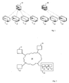
- Fig. 1 shows a network comprising a first switch 10 serving four base stations (BS) 11 to 14, and a second switch 20 serving three base stations 21 to 23.
- BS base stations
- Each base station 11-14, 21-23 has a highly accurate oscillator while each network switch 10, 20 supplies a less accurate, but common timing signal to all base stations connected to it.
- Each base station 11-14, 21-23 measures the difference between the clock speeds of the internal oscillator and the timing signal from the network and reports the difference to a central node which is aware of the network topology (e.g. the Operations and Maintenance Center, OMC).
- OMC Operations and Maintenance Center
- a difference between the timings can be due to the oscillator of the base station being defective, the network frequency being off its nominal value (may or may not be within the specification) or a combination thereof.
- a central node compares the reported offsets from all base stations connected to the same network clock segment which is a segment of the network that receives the timing signal from the same source. If the network topology is a tree, the network clock segments of the network may be trees, too.
- the offset is due to the network timing being off the nominal frequency which may be within or outside the specification.
- the oscillator of that base station standing out is off frequency. An alarm for that component may be raised to the network/base station operator.
- thresholds based on offset mean and standard deviation may be applied to identify faulty oscillators. This approach is illustrated in the following: First, frequency offsets from all base stations are measured over some initial time. Then, upper and lower thresholds from the standard deviation and mean value of those initial measurements are determined. A base station that reports continuously offsets below or above the thresholds is assumed to be off frequency. Standard deviation, mean, upper and lower thresholds should be adapted continuously by discarding old measurement values and taking new ones into account. This will ensure necessary adaptations of the thresholds due to reference clock drifts.
- a cross-correlation of measurements is applied to identify faulty oscillators. If the reference clock drift over time is slow compared to the rate of the measurement reports, it may be possible to mutually cross-correlate time interpolated measurement reports from all base stations. All cross-correlation values should be in a similar range as the deviation of the reference clock should have similar effect on the offset reports from all base stations. Upper and lower thresholds can be determined from the cross-correlation mean and standard deviation in this case as well. Once a base stations oscillator starts deviating from the nominal frequency, it is expected that the mutual cross-correlation values between this base station measurements and all others exceeds the defined thresholds.
- this solution may also be used to identify degrading oscillators in an early stage when they slowly drift away from their nominal frequency.
- the above approaches to correlate frequency offsets are only exemplary illustrations for the processing of offsets and many other offset correlations are possible as well to identify defective oscillators.
- the nominal clock speeds be 1kHz for all oscillators and network clocks.
- the first switch 10 be off frequency at 1,005Hz and the second switch 20 at 998Hz.
- the OMC know that base stations 11 to 14 are connected to the first switch 10 and base stations 21 to 23 are connected to the second switch 20.
- all oscillators be at the nominal frequency, except the one of BS 12 being at 950Hz.
- Fig. 2 shows an embodiment of the invention where two network entities 32, 33, e.g. base stations, are connected to a network 30.
- a reference clock generator 31 generates a reference clock signal which is distributed to the network entities 32, 33 via the network 30, e.g. a telecommunications network.
- Each network entity 32, 33 comprises a communications unit 35, a frequency offset measuring unit 36, and an oscillator 37 (shown only for network entity 33).
- the communications unit 35 receives the reference clock signal from the reference clock 31 via the telecommunications network 30.
- the reference clock signal may be recovered from the physical layer of the network, so no dedicated signaling is used.
- a base station has a local oscillator that locks with a PLL to the physical layer clock as it is provided by its peer.
- the base station is "slave” regarding the physical link clocking, and it recovers the clock from the received data on physical layer level.
- a framer chip provides in case of E1/T1 a fraction of this recovered clock signal on an output pin, and that clock may be used in the base station as reference clock (8kHz frame sync pulse). Similar clock recovering applies for other synchronous interfaces e.g. STMx/OCx, etc.
- the present invention uses the recovered network clock as reference clock to generate frequency offsets, unlike the prior art where the recovered network clock is used to discipline the oscillator by imposing the network clock on it.
- the recovered network clock is not precise (i.e. is off frequency and/or exhibits drift or wander), the frequency offsets of the oscillators receiving the same clock signal all behave similarly, while the oscillators in the prior art would be mis-adjusted.
- oscillators operating at a higher frequency can be supervised with the present invention where a lower frequency reference clock (e.g. 8 KHz) is derived from the network.
- the reference clock is input to a counter which generates a gate signal for a pre-determined time period (e.g. one second).
- the gate signal is applied to a second counter which counts the cycles of the high frequency oscillator during this time period. The difference between the counted cycles and an expected nominal cycle value is then considered as offset value for the oscillator. Since all oscillators generate their respective gate signal from the same reference clock signal, inaccuracies in the reference signal will affect all offset values uniformly.
- the communications unit 35 provides the reference clock to the frequency offset measuring unit 36 which further receives the local oscillator clock signal from the oscillator 37.
- the frequency offset measuring unit 36 determines the difference (offset) between the reference clock frequency and the oscillator frequency.
- the frequency offset is then provided to the communications unit 35 which sends a frequency offset report via the telecommunications network 30 to a control unit 34.
- the communications unit 35 can use whatever communications protocol is provided by the telecommunications network 30 to transmit the frequency offset reports to the control unit 34. If the telecommunications network 30 can carry packet data traffic, the communications unit 35 sends the offset report as data message to the control unit 34.
- Base stations usually have a dedicated communication path to an OMC (Operations, Administration and Control center), which is a good choice for the clock supervising entity in the UMTS UTRAN case.
- This path may be used to send the offsets in messages.
- the underlying protocols and layers may be IPoA, TCP, UDP, SNMP, etc.
- the offset reports may be sent via a packet network to the clock supervising entity.
- the control unit 34 analyses the frequency offsets of all network units 32, 33 that are connected to the same reference clock 31, i.e. that receive the same reference clock signal. Control unit 34 correlates the received frequency offsets to determine whether they show all more or less the same behavior (i.e. a similar offset). If the offset of one network entity differs significantly from the others, one can reasonably assume that the oscillator of that network entity is off frequency, e.g. faulty. Fig. 2 shows only 2 network units 32, 33 for keeping the example and the figure simple. However, this approach is more accurate the more network entities submit offset reports to the control unit 34 for correlation analysis. Thus, preferred embodiments usually have more than the shown 2 network entities 32, 33.
- the concept of the present invention is not limited to wireless networks, but can be applied to other networks where a distributed timing signal is less accurate than the signal required at the network leafs.
Landscapes
- Engineering & Computer Science (AREA)
- Computer Networks & Wireless Communication (AREA)
- Signal Processing (AREA)
- Theoretical Computer Science (AREA)
- Physics & Mathematics (AREA)
- General Engineering & Computer Science (AREA)
- General Physics & Mathematics (AREA)
- Environmental & Geological Engineering (AREA)
- Mobile Radio Communication Systems (AREA)
- Synchronisation In Digital Transmission Systems (AREA)
- Stabilization Of Oscillater, Synchronisation, Frequency Synthesizers (AREA)
Claims (10)
- Procédé de supervision de la fréquence d'une pluralité d'oscillateurs (37) conçus pour fonctionner à une fréquence nominale, comprenant les étapes suivantes :Réception d'une fréquence de référence sur chaque oscillateur de la pluralité d'oscillateurs (37) ;Mesure du décalage entre la fréquence de chaque oscillateur (37) et la fréquence de référence ; etCorrélation des décalages en fréquence des oscillateurs (37) pour déterminer si un ou plusieurs des oscillateurs (37) fonctionnent avec une fréquence qui est différente de la fréquence nominale.
- Procédé selon la revendication 1, dans lequel la précision de la fréquence de référence est inférieure à la précision des oscillateurs (37).
- Procédé selon la revendication 1, dans lequel les oscillateurs (37) sont disposés dans un équipement de réseau distribué au sein d'un réseau de télécommunications (30).
- Procédé selon la revendication 3, comprenant l'étape de signalisation du décalage en fréquence de chaque oscillateur (37) à une entité de réseau en amont où les décalages en fréquence sont comparés les uns aux autres.
- Procédé selon la revendication 1, dans lequel les décalages en fréquence sont triés conformément à leurs valeurs respectives pour identifier un oscillateur (37) fonctionnant à une fréquence non nominale.
- Procédé selon la revendication 1, comprenant l'étape de comparaison des décalages de tous les oscillateurs (37) dans un réseau (30) et de regroupement de ceux qui présentent le même comportement de décalage en vue d'identifier les oscillateurs (37) qui reçoivent la même fréquence de référence.
- Système de supervision des fréquences d'une pluralité d'oscillateurs (37) conçus pour fonctionner à une fréquence nominale dans un réseau (30), comprenant :un générateur de fréquence de référence (31) pour générer un signal de fréquence de référence ;des moyens de distribution de fréquence pour distribuer le signal de fréquence de référence dans le réseau (30) ;des moyens de mesure pour mesurer les décalages des oscillateurs en déterminant la différence entre les fréquences des oscillateurs et la fréquence de référence du signal de fréquence de référence ; etune unité de commande (34) pour corréler les décalages en fréquence des oscillateurs (37) afin de déterminer si un oscillateur (37) fonctionne avec une fréquence qui est différente de la fréquence nominale.
- Système selon la revendication 7, dans lequel le réseau (30) est un réseau de télécommunications et les oscillateurs (37) sont disposés dans des stations de base sans fil.
- Système selon la revendication 7, comprenant des moyens de communication (35) pour transmettre les décalages d'oscillateur des oscillateurs (37) qui sont distribués dans le réseau (30) vers un centre d'exploitation et de maintenance du réseau.
- Système selon la revendication 7, dans lequel la fréquence de référence est délivrée par une station d'accueil de réseau de raccordement.
Priority Applications (3)
| Application Number | Priority Date | Filing Date | Title |
|---|---|---|---|
| EP07116093A EP2037602B1 (fr) | 2007-09-11 | 2007-09-11 | Système et procédé pour la supervision d'une pluralité d'oscillateurs dans un réseau |
| AT07116093T ATE478482T1 (de) | 2007-09-11 | 2007-09-11 | System und verfahren zur überwachung mehrer oszillatoren in einem netzwerk |
| DE602007008569T DE602007008569D1 (de) | 2007-09-11 | 2007-09-11 | System und Verfahren zur Überwachung mehrer Oszillatoren in einem Netzwerk |
Applications Claiming Priority (1)
| Application Number | Priority Date | Filing Date | Title |
|---|---|---|---|
| EP07116093A EP2037602B1 (fr) | 2007-09-11 | 2007-09-11 | Système et procédé pour la supervision d'une pluralité d'oscillateurs dans un réseau |
Publications (2)
| Publication Number | Publication Date |
|---|---|
| EP2037602A1 EP2037602A1 (fr) | 2009-03-18 |
| EP2037602B1 true EP2037602B1 (fr) | 2010-08-18 |
Family
ID=38952112
Family Applications (1)
| Application Number | Title | Priority Date | Filing Date |
|---|---|---|---|
| EP07116093A Active EP2037602B1 (fr) | 2007-09-11 | 2007-09-11 | Système et procédé pour la supervision d'une pluralité d'oscillateurs dans un réseau |
Country Status (3)
| Country | Link |
|---|---|
| EP (1) | EP2037602B1 (fr) |
| AT (1) | ATE478482T1 (fr) |
| DE (1) | DE602007008569D1 (fr) |
Families Citing this family (1)
| Publication number | Priority date | Publication date | Assignee | Title |
|---|---|---|---|---|
| DE102013218328B3 (de) | 2013-09-12 | 2014-06-26 | Siemens Aktiengesellschaft | Verfahren zur Lokalisierung einer Frequenzabweichung in einem Kommunikationsnetz und entsprechendes Kommunikationsnetz |
Family Cites Families (6)
| Publication number | Priority date | Publication date | Assignee | Title |
|---|---|---|---|---|
| GB1263276A (en) * | 1969-04-14 | 1972-02-09 | Marconi Co Ltd | Improvements in or relating to clock oscillator arrangements |
| DE3638947C2 (de) | 1986-11-14 | 1995-08-31 | Bosch Gmbh Robert | Verfahren zur Synchronisation von Rechnern eines Mehrrechnersystems und Mehrrechnersystem |
| US6005902A (en) * | 1997-08-29 | 1999-12-21 | Lucent Technologies Inc. | Providing timing to an external system |
| EP1209850B1 (fr) | 2000-11-22 | 2007-04-04 | Lucent Technologies Inc. | Système et procédé de synchronisation des éléments de réseau |
| US7023884B2 (en) * | 2000-12-19 | 2006-04-04 | Lucent Technologies Inc. | Clock offset estimation with bias correction |
| US7257133B2 (en) * | 2002-09-30 | 2007-08-14 | Lucent Technologies Inc. | Method for estimating offset for clocks at network elements |
-
2007
- 2007-09-11 EP EP07116093A patent/EP2037602B1/fr active Active
- 2007-09-11 AT AT07116093T patent/ATE478482T1/de not_active IP Right Cessation
- 2007-09-11 DE DE602007008569T patent/DE602007008569D1/de active Active
Also Published As
| Publication number | Publication date |
|---|---|
| DE602007008569D1 (de) | 2010-09-30 |
| EP2037602A1 (fr) | 2009-03-18 |
| ATE478482T1 (de) | 2010-09-15 |
Similar Documents
| Publication | Publication Date | Title |
|---|---|---|
| US9813175B2 (en) | Method for detecting timing references affected by a change in path delay asymmetry between nodes in a communication network | |
| KR101557185B1 (ko) | 투명 클럭 동기화 실패를 검출하기 위한 방법 및 이와 관련된 보호 스킴 | |
| US10355800B2 (en) | Multi-path time synchronization | |
| US20110142078A1 (en) | Network timing topology via network manager | |
| EP2333993A1 (fr) | Gestion automatique de protocoles de synchronisation à base d'horodatage | |
| CN106788838B (zh) | 一种电力时间同步系统鲁棒控制的系统及方法 | |
| CN102957545B (zh) | 同步网络时钟的维护方法及装置 | |
| JP2008206135A (ja) | 遠隔監視装置及び遠隔監視システム | |
| US9021291B2 (en) | Synchronous network | |
| EP2037602B1 (fr) | Système et procédé pour la supervision d'une pluralité d'oscillateurs dans un réseau | |
| US20250184110A1 (en) | Communication device and communication management device | |
| CN106647228A (zh) | 一种换流站主时钟故障判断系统 | |
| US20250105938A1 (en) | Accuracy monitoring of clock synchronized systems | |
| CN116866157B (zh) | 一种基于5g纵联差动保护的数据传输方法 | |
| CN113114450B (zh) | 全网时钟反馈方法及系统 | |
| EP3420666B1 (fr) | Procédés et systèmes pour estimer une asymétrie | |
| KR102509057B1 (ko) | 네트워크 관제 시스템 및 그 방법 | |
| CN117221095A (zh) | 时间同步故障的分析方法、装置及系统 | |
| TW202427985A (zh) | 一種同步時鐘源之劣化判斷系統、方法及其電腦可讀媒介 | |
| CN105530695A (zh) | 一种 t1 数据信号的最大时间间隔误差的估计方法 | |
| CN103139794A (zh) | 一种生成射频单元退服告警信息的方法及系统 | |
| CN106788851A (zh) | 时钟故障的告警方法和装置 | |
| SECTOR et al. | ITU-Tg. 7710/Y. 1701 | |
| CN108234053A (zh) | 一种t1数据信号的最大时间间隔误差的估计方法 |
Legal Events
| Date | Code | Title | Description |
|---|---|---|---|
| PUAI | Public reference made under article 153(3) epc to a published international application that has entered the european phase |
Free format text: ORIGINAL CODE: 0009012 |
|
| AK | Designated contracting states |
Kind code of ref document: A1 Designated state(s): AT BE BG CH CY CZ DE DK EE ES FI FR GB GR HU IE IS IT LI LT LU LV MC MT NL PL PT RO SE SI SK TR |
|
| AX | Request for extension of the european patent |
Extension state: AL BA HR MK RS |
|
| RAP3 | Party data changed (applicant data changed or rights of an application transferred) |
Owner name: LUCENT TECHNOLOGIES INC. |
|
| 17P | Request for examination filed |
Effective date: 20090918 |
|
| AKX | Designation fees paid |
Designated state(s): AT BE BG CH CY CZ DE DK EE ES FI FR GB GR HU IE IS IT LI LT LU LV MC MT NL PL PT RO SE SI SK TR |
|
| GRAP | Despatch of communication of intention to grant a patent |
Free format text: ORIGINAL CODE: EPIDOSNIGR1 |
|
| GRAS | Grant fee paid |
Free format text: ORIGINAL CODE: EPIDOSNIGR3 |
|
| GRAA | (expected) grant |
Free format text: ORIGINAL CODE: 0009210 |
|
| RAP1 | Party data changed (applicant data changed or rights of an application transferred) |
Owner name: ALCATEL-LUCENT USA INC. |
|
| AK | Designated contracting states |
Kind code of ref document: B1 Designated state(s): AT BE BG CH CY CZ DE DK EE ES FI FR GB GR HU IE IS IT LI LT LU LV MC MT NL PL PT RO SE SI SK TR |
|
| REG | Reference to a national code |
Ref country code: GB Ref legal event code: FG4D |
|
| REG | Reference to a national code |
Ref country code: CH Ref legal event code: EP |
|
| REG | Reference to a national code |
Ref country code: IE Ref legal event code: FG4D |
|
| REF | Corresponds to: |
Ref document number: 602007008569 Country of ref document: DE Date of ref document: 20100930 Kind code of ref document: P |
|
| REG | Reference to a national code |
Ref country code: NL Ref legal event code: VDEP Effective date: 20100818 |
|
| LTIE | Lt: invalidation of european patent or patent extension |
Effective date: 20100818 |
|
| PG25 | Lapsed in a contracting state [announced via postgrant information from national office to epo] |
Ref country code: LT Free format text: LAPSE BECAUSE OF FAILURE TO SUBMIT A TRANSLATION OF THE DESCRIPTION OR TO PAY THE FEE WITHIN THE PRESCRIBED TIME-LIMIT Effective date: 20100818 Ref country code: AT Free format text: LAPSE BECAUSE OF FAILURE TO SUBMIT A TRANSLATION OF THE DESCRIPTION OR TO PAY THE FEE WITHIN THE PRESCRIBED TIME-LIMIT Effective date: 20100818 Ref country code: FI Free format text: LAPSE BECAUSE OF FAILURE TO SUBMIT A TRANSLATION OF THE DESCRIPTION OR TO PAY THE FEE WITHIN THE PRESCRIBED TIME-LIMIT Effective date: 20100818 |
|
| PG25 | Lapsed in a contracting state [announced via postgrant information from national office to epo] |
Ref country code: IS Free format text: LAPSE BECAUSE OF FAILURE TO SUBMIT A TRANSLATION OF THE DESCRIPTION OR TO PAY THE FEE WITHIN THE PRESCRIBED TIME-LIMIT Effective date: 20101218 Ref country code: CY Free format text: LAPSE BECAUSE OF FAILURE TO SUBMIT A TRANSLATION OF THE DESCRIPTION OR TO PAY THE FEE WITHIN THE PRESCRIBED TIME-LIMIT Effective date: 20100818 Ref country code: BG Free format text: LAPSE BECAUSE OF FAILURE TO SUBMIT A TRANSLATION OF THE DESCRIPTION OR TO PAY THE FEE WITHIN THE PRESCRIBED TIME-LIMIT Effective date: 20101118 Ref country code: SI Free format text: LAPSE BECAUSE OF FAILURE TO SUBMIT A TRANSLATION OF THE DESCRIPTION OR TO PAY THE FEE WITHIN THE PRESCRIBED TIME-LIMIT Effective date: 20100818 Ref country code: PL Free format text: LAPSE BECAUSE OF FAILURE TO SUBMIT A TRANSLATION OF THE DESCRIPTION OR TO PAY THE FEE WITHIN THE PRESCRIBED TIME-LIMIT Effective date: 20100818 Ref country code: PT Free format text: LAPSE BECAUSE OF FAILURE TO SUBMIT A TRANSLATION OF THE DESCRIPTION OR TO PAY THE FEE WITHIN THE PRESCRIBED TIME-LIMIT Effective date: 20101220 |
|
| PG25 | Lapsed in a contracting state [announced via postgrant information from national office to epo] |
Ref country code: GR Free format text: LAPSE BECAUSE OF FAILURE TO SUBMIT A TRANSLATION OF THE DESCRIPTION OR TO PAY THE FEE WITHIN THE PRESCRIBED TIME-LIMIT Effective date: 20101119 Ref country code: SE Free format text: LAPSE BECAUSE OF FAILURE TO SUBMIT A TRANSLATION OF THE DESCRIPTION OR TO PAY THE FEE WITHIN THE PRESCRIBED TIME-LIMIT Effective date: 20100818 Ref country code: LV Free format text: LAPSE BECAUSE OF FAILURE TO SUBMIT A TRANSLATION OF THE DESCRIPTION OR TO PAY THE FEE WITHIN THE PRESCRIBED TIME-LIMIT Effective date: 20100818 Ref country code: NL Free format text: LAPSE BECAUSE OF FAILURE TO SUBMIT A TRANSLATION OF THE DESCRIPTION OR TO PAY THE FEE WITHIN THE PRESCRIBED TIME-LIMIT Effective date: 20100818 Ref country code: BE Free format text: LAPSE BECAUSE OF FAILURE TO SUBMIT A TRANSLATION OF THE DESCRIPTION OR TO PAY THE FEE WITHIN THE PRESCRIBED TIME-LIMIT Effective date: 20100818 |
|
| PG25 | Lapsed in a contracting state [announced via postgrant information from national office to epo] |
Ref country code: MC Free format text: LAPSE BECAUSE OF NON-PAYMENT OF DUE FEES Effective date: 20100930 Ref country code: DK Free format text: LAPSE BECAUSE OF FAILURE TO SUBMIT A TRANSLATION OF THE DESCRIPTION OR TO PAY THE FEE WITHIN THE PRESCRIBED TIME-LIMIT Effective date: 20100818 |
|
| PG25 | Lapsed in a contracting state [announced via postgrant information from national office to epo] |
Ref country code: SK Free format text: LAPSE BECAUSE OF FAILURE TO SUBMIT A TRANSLATION OF THE DESCRIPTION OR TO PAY THE FEE WITHIN THE PRESCRIBED TIME-LIMIT Effective date: 20100818 Ref country code: EE Free format text: LAPSE BECAUSE OF FAILURE TO SUBMIT A TRANSLATION OF THE DESCRIPTION OR TO PAY THE FEE WITHIN THE PRESCRIBED TIME-LIMIT Effective date: 20100818 Ref country code: IT Free format text: LAPSE BECAUSE OF FAILURE TO SUBMIT A TRANSLATION OF THE DESCRIPTION OR TO PAY THE FEE WITHIN THE PRESCRIBED TIME-LIMIT Effective date: 20100818 Ref country code: RO Free format text: LAPSE BECAUSE OF FAILURE TO SUBMIT A TRANSLATION OF THE DESCRIPTION OR TO PAY THE FEE WITHIN THE PRESCRIBED TIME-LIMIT Effective date: 20100818 Ref country code: CZ Free format text: LAPSE BECAUSE OF FAILURE TO SUBMIT A TRANSLATION OF THE DESCRIPTION OR TO PAY THE FEE WITHIN THE PRESCRIBED TIME-LIMIT Effective date: 20100818 |
|
| PLBE | No opposition filed within time limit |
Free format text: ORIGINAL CODE: 0009261 |
|
| STAA | Information on the status of an ep patent application or granted ep patent |
Free format text: STATUS: NO OPPOSITION FILED WITHIN TIME LIMIT |
|
| PG25 | Lapsed in a contracting state [announced via postgrant information from national office to epo] |
Ref country code: ES Free format text: LAPSE BECAUSE OF FAILURE TO SUBMIT A TRANSLATION OF THE DESCRIPTION OR TO PAY THE FEE WITHIN THE PRESCRIBED TIME-LIMIT Effective date: 20101129 |
|
| 26N | No opposition filed |
Effective date: 20110519 |
|
| PG25 | Lapsed in a contracting state [announced via postgrant information from national office to epo] |
Ref country code: IE Free format text: LAPSE BECAUSE OF NON-PAYMENT OF DUE FEES Effective date: 20100911 |
|
| REG | Reference to a national code |
Ref country code: DE Ref legal event code: R097 Ref document number: 602007008569 Country of ref document: DE Effective date: 20110519 |
|
| PG25 | Lapsed in a contracting state [announced via postgrant information from national office to epo] |
Ref country code: MT Free format text: LAPSE BECAUSE OF FAILURE TO SUBMIT A TRANSLATION OF THE DESCRIPTION OR TO PAY THE FEE WITHIN THE PRESCRIBED TIME-LIMIT Effective date: 20100818 |
|
| REG | Reference to a national code |
Ref country code: CH Ref legal event code: PL |
|
| PG25 | Lapsed in a contracting state [announced via postgrant information from national office to epo] |
Ref country code: CH Free format text: LAPSE BECAUSE OF NON-PAYMENT OF DUE FEES Effective date: 20110930 Ref country code: LI Free format text: LAPSE BECAUSE OF NON-PAYMENT OF DUE FEES Effective date: 20110930 |
|
| PG25 | Lapsed in a contracting state [announced via postgrant information from national office to epo] |
Ref country code: LU Free format text: LAPSE BECAUSE OF NON-PAYMENT OF DUE FEES Effective date: 20100911 Ref country code: HU Free format text: LAPSE BECAUSE OF FAILURE TO SUBMIT A TRANSLATION OF THE DESCRIPTION OR TO PAY THE FEE WITHIN THE PRESCRIBED TIME-LIMIT Effective date: 20110219 |
|
| PG25 | Lapsed in a contracting state [announced via postgrant information from national office to epo] |
Ref country code: TR Free format text: LAPSE BECAUSE OF FAILURE TO SUBMIT A TRANSLATION OF THE DESCRIPTION OR TO PAY THE FEE WITHIN THE PRESCRIBED TIME-LIMIT Effective date: 20100818 |
|
| REG | Reference to a national code |
Ref country code: FR Ref legal event code: GC Effective date: 20140715 |
|
| REG | Reference to a national code |
Ref country code: FR Ref legal event code: RG Effective date: 20141015 |
|
| REG | Reference to a national code |
Ref country code: FR Ref legal event code: PLFP Year of fee payment: 9 |
|
| REG | Reference to a national code |
Ref country code: FR Ref legal event code: PLFP Year of fee payment: 10 |
|
| REG | Reference to a national code |
Ref country code: FR Ref legal event code: PLFP Year of fee payment: 11 |
|
| REG | Reference to a national code |
Ref country code: FR Ref legal event code: PLFP Year of fee payment: 12 |
|
| PGFP | Annual fee paid to national office [announced via postgrant information from national office to epo] |
Ref country code: FR Payment date: 20210812 Year of fee payment: 15 |
|
| PG25 | Lapsed in a contracting state [announced via postgrant information from national office to epo] |
Ref country code: FR Free format text: LAPSE BECAUSE OF NON-PAYMENT OF DUE FEES Effective date: 20220930 |
|
| PGFP | Annual fee paid to national office [announced via postgrant information from national office to epo] |
Ref country code: DE Payment date: 20250730 Year of fee payment: 19 |
|
| PGFP | Annual fee paid to national office [announced via postgrant information from national office to epo] |
Ref country code: GB Payment date: 20250731 Year of fee payment: 19 |