EP2037731B1 - Plate-forme rotative annulaire pour salle de traite - Google Patents
Plate-forme rotative annulaire pour salle de traite Download PDFInfo
- Publication number
- EP2037731B1 EP2037731B1 EP07748486.3A EP07748486A EP2037731B1 EP 2037731 B1 EP2037731 B1 EP 2037731B1 EP 07748486 A EP07748486 A EP 07748486A EP 2037731 B1 EP2037731 B1 EP 2037731B1
- Authority
- EP
- European Patent Office
- Prior art keywords
- platform
- annular
- underside
- protruding reinforcing
- reinforcing portion
- Prior art date
- Legal status (The legal status is an assumption and is not a legal conclusion. Google has not performed a legal analysis and makes no representation as to the accuracy of the status listed.)
- Active
Links
Images

Classifications
-
- A—HUMAN NECESSITIES
- A01—AGRICULTURE; FORESTRY; ANIMAL HUSBANDRY; HUNTING; TRAPPING; FISHING
- A01K—ANIMAL HUSBANDRY; AVICULTURE; APICULTURE; PISCICULTURE; FISHING; REARING OR BREEDING ANIMALS, NOT OTHERWISE PROVIDED FOR; NEW BREEDS OF ANIMALS
- A01K1/00—Housing animals; Equipment therefor
- A01K1/12—Milking stations
- A01K1/126—Carousels
Definitions
- the present invention relates to an annular rotary platform for a milking parlour, wherein the platform is formed of a cementitious material.
- the size of a rotary parlour must be adapted to individual farmer's available space and number of cows.
- a platform of a rotary parlour adapted to receive about 20 to 100 cows is too large to be transported. Therefore, the assembly of rotary parlours in situ is required.
- Milking cows have a weight of about 600-900 kg.
- the platform of a rotary parlour has to have a considerable strength such the platform will not be deflected by the weight of the cows during the rotary motion of the platform and when the cows walk on and back off the platform.
- NZ 270 955 shows a rotary milking parlour including an annular platform.
- the platform consists of concrete and it has a substantially even thickness.
- a plurality of radially directed steel ribs is arranged on the underside of the platform.
- the annular platform will be substantially stiff in a radial direction but less stiff in a direction along its circular extension. The reduced stiffness in this direction makes it is possible for the platform to maintain a continuous contact, via a circular rail member attached on the underside of the platform, with a number of rolling members arranged below the platform.
- US 3,710,526 describes an annular compression beam for use in a roof, floor or ceiling in a building.
- the annular compression beam comprises a precast annular girder of concrete and radially extending tendons.
- the inner ends of the tendons are attached to a stress ring and the outer ends are provided with holding and tensioning means.
- the tendons are placed in a tensioned state and while the tendons are in a tensioned state concrete is poured. After the concrete has set, the release of the tension at the inner end and the outer end places the concrete in a compression.
- the object of the present invention is to achieve a rotary platform for a milking parlour, which has a reliable function, a good strength and is possible to manufacture to a relatively low cost.
- the cementitious material may be concrete.
- the platform achieves in an area provided with such a protruding reinforcing portion of a cementitious material an increased thickness and an increased strength.
- the protruding reinforcing portion on the underside of the platform may be provided with a suitable design in order achieve a desired strength in different areas and directions of the platform.
- the protruding reinforcing portion and the remaining part of the platform are formed during the same casting process of the cementitious material. Thereby, it is possible to manufacture the platform in a quick and easy manner.
- said protruding reinforcing portion has an elongated shape on the underside of the platform.
- Said protruding reinforcing portion may have an extension in a substantially radial direction on the underside of the annular platform.
- the platform is quite rigid but in this manner the annular platform will be somewhat stiffer in a radial direction than in a direction along its circular extension.
- the platform comprises a plurality of such protruding reinforcing portions arranged in different positions on the underside of the platform. Thereby, it is possible to provide the platform with an increased strength in different areas located at a distance from each other.
- adjacent protruding reinforcing portion are arranged at substantially equal distances from each other on the underside of the platform. Thereby, it is possible to give the floor in the milking stalls on the upper side of the annular platform a substantially corresponding strength.
- the at least one protruding reinforcing portion has a substantially plane end surface located in the vicinity of an inner radial surface of the annular platform.
- the end surface may be located substantially exactly at the inner radial surface of the annular platform or at a smaller distance from the inner radial surface.
- Such an end surface may be used for attachment of equipment of different kinds used on the rotary platform.
- the at least one protruding reinforcing portion may have a substantially plane end surface located in the vicinity of an outer radial surface of the annular platform. This end surface may also be used for attachment of equipment of different kinds used on the rotary platform.
- the platform comprises at least one connecting member constituting a substantially rigid connection between the platform and a circular rail member arranged on an underside of the platform.
- Rotary platforms have many times such a circular rail member on an underside for allowing rotation of the platform arranged on a number of supporting roller arranged below the platform. Thereby, it is possible to rotate the platform with a low friction and a desired velocity.
- the connecting member may be a bar or a plate of a strength metal material such as steel.
- a lower portion of the connecting member may be fixedly connected to the circular rail member for example by welding.
- said connecting member constitutes a connection between the protruding reinforcing portion of the platform and the circular rail member.
- the platform Since the platform has its highest strength here, it is suitable to connect an upper portion of the connecting member to the platform in this area.
- Said connecting member may be connected to the platform by means of an upper end portion cast into the cementitious material of the platform. Thereby, the upper end portion of the connecting member achieves a strength and rigid connection with the platform.
- the platform comprises at least one reinforcing element cast into the cementitious material.
- the reinforcing element may constitute one or several reinforcement bar.
- a reinforcing element of a strength metal material embedded in a cementitious material supplies a considerable strength to the platform.
- the reinforcing elements may be elongated and have an extension in a radial direction of the platform in order to further increase the stiffness of the platform in this direction.
- the protruding reinforcing portion may comprise at least one reinforcing element cast into the cementitious material. Thereby, the strength of the protruding reinforcing portion will be considerably increased.
- the upper portion of the connecting member which is embedded in the cementitious material, may be connected to one or several of the reinforcing elements by means of, for example, welding. Thereby, the weight from the platform and the cows standing on the platform will be transferred from the reinforcing element, via the connecting member, to the circular rail member.
- the annular platform may comprise an inner ring of a metal material forming an inner radial surface of the platform. Such an inner ring supplies strength to the platform in the vicinity of the inner radial surface. Furthermore, the inner ring may be used as an inner wall surface of a mould for forming the cemetitious material during the casting process.
- the annular platform may comprise an outer ring of a metal material forming an outer radial surface of the platform. Such an outer ring supplies strength to the platform in the vicinity of the outer radial surface. Furthermore, the outer ring may be used as an outer wall surface of a mould for forming the cemetitious material during the casting process. Alternatively, the platform can be manufactured without such metal rings.
- the annular platform has an upper surface with an inner circumference edge located at a higher level than an outer circumference edge.
- the annular platform has a plane upper surface sloping about 3° in relation to a horizontal plane. This simplifies the cleaning of the platform because water and dirt rinse off easily.
- a sloping of the platform is preferred if the milking members are attached by operators working from the outside of the platform.
- the annular platform has an upper surface with an inner circumference edge located at a lower level than an outer circumference edge. Such a sloping of the platform is preferred if the milking members are attached by operators working from the inside of the platform.
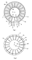
- Fig 1 shows a rotary parlour for milking of cows 1.
- the cows 1 to be milked are arranged to walk through an entry 2 to enter an annular platform 3.
- the platform 3 is rotatably arranged around a substantially vertical axis 4.
- the platform 3 is substantially formed of a cementitious material such a concrete.
- the platform 3 has a substantially plane upper surface 3a for supporting cows 1 to be milked.
- an inner circumference edge 3a' of the annular platform 3 is located at a somewhat higher level than an outer circumference edge 3a" of the platform 3. Consequently, the upper surface 3a of the platform has a smooth sloop in relation to a horizontal plane. Thereby, it is easy to clean the platform 3 since water and dirt rinse off easily.
- a plurality of fence arrangements 5 are mounted on the platform, which divide the platform 3 into stalls 6 for receiving individual cows 1.
- the fence arrangements 5 have a substantially radial extension on the platform 3 in relation to the vertical axis 4.
- the fence arrangement 5 comprises a stiff cabinet 5a arranged at an outer radial position of the platform 3, which constitute a supporting element of the fence arrangement 5.
- the cabinet 5a has an inner space, which may accommodate milking equipment and other components in the stall 6.
- An alternative to the cabinet 5a is a post or the like arranged at an outer position of the platform 3.
- the stalls 6 are here arranged such that the cows face inwards from the stalls 6 and operators 8 work from the outside of the annular platform 3.
- An operator 8 may, for example, attach milking members to the cows 1 when they have entered a stall 6.
- the cows rotate nearly 360° on the platform 3 during a milking operation.
- the cows 1 leave the stall 6 and the platform 3 through an exit 9 after having been milked and possibly fed during the milking operation.
- Fig 2 shows a view of the platform 3 from the underside.
- the platform 3 has a lower surface 3b comprising substantially plane areas 3c and areas comprising protruding reinforcing portions in the form of ribs 3d.
- the ribs 3d have an elongated shape and an extension in a substantially radial direction on the underside of the annular platform 3. Adjacent ribs 3d are arranged at substantially equal distances from each other around the lower surface 3b of the annular platform 3.
- the ribs 3d have a substantially plane end surface 3d' located in the vicinity of an inner radial surface 3e of the annular platform and a substantially plane end surface 3d" located in the vicinity of an outer radial surface 3f of the annular platform.
- end surfaces 3d', 3d" of the ribs 3d are located at a smaller distance from the inner radial surface 3e and the outer radial surface 3f of the platform.
- a circular rail member 10 is rigidly connected to the underside of the platform 3.
- Fig. 3 shows a view from the inside of the annular platform 3.
- the circular rail member 10 is connected to the ribs 3d of the platform by means of connecting members in the form of flat steel plates 11. A lower portion of the steel plates 11 is welded to the circular rail member 10 and a upper portion of the steel plates 11 is cast into the cementitious material forming the ribs 3d.
- the rail member 10 has a lower surface to be in contact with a plurality of rollers 12 arranged on stands 13 in different positions below the circular rail member 10.
- One stand 13 with one roller 12 is shown in Fig. 3 .
- the stand 13 is arranged on a floor 14 located below the platform 3 by means of a bolt connection 15. At least one of the rollers 12 is driven by a motor. Thereby, it is possible to perform a rotary motion of the platform 3 with a desired rotary speed and a minimum of friction.
- the inner radial surface 3e of the annular platform can be formed by an inner ring of a metal material 16.
- the substantially plane end surfaces 3d' of the ribs 3d constitute a surface which can be used for attachment of equipment of different kind used on the rotary platform.
- Fig. 3 shows such equipment in the form of a schematically disclosed hanger 17 for supporting of pipelines and electrical conduits etc. It is also possible to use the plane outer end surfaces 3d" of the ribs 3d for attachment of equipment of different kind.
- Fig. 4 shows a rib form 18 for forming one of the ribs 3d on the underside of the platform 3.
- the rib form 18 is constructed of an elongated left half 18a and an elongated right half 18b which are connected to each other at a bottom surface.
- Each of the elongated halves 18a, b comprise an upper substantially plane surface 18a', 18b'.
- the halves 18a, b forms, in a connected state, an elongated cavity 19 between the upper plane surfaces 18a', 18b'.
- the rib form 18 also comprises an inner rib blocking part 18c and an outer rib blocking part 18d.
- the inner rib blocking part 18c and the outer rib blocking part 18d are attachable to the halves 18a, b at opposite ends.
- the inner rib blocking part 18c has a wall element 18c' which defines the plane inner end surfaces 3d' of a rib 3d.
- the outer rib blocking part 18d has a corresponding wall element 18d' which defines the plane outer end surfaces 3d" of a rib 3d.
- the rib form 18 comprises an opening 20 at a bottom portion of the cavity 19 through which the flat steel plate 11 is insertable.
- the first reinforcing element 21 is mountable in the cavity 19 by means of bolts extending through corresponding holes in the wall elements 18c', 18d' and the tubular end elements of the reinforcing element 21.
- the second reinforcing element 22 is also welded to the flat steel plate 11.
- the assembly work of the rib forms 18 may be performed in a factory or the like before the platform components are delivered to site. In case where factory pre-assemble is not possible, the rib forms 18 will be assembled in situ.
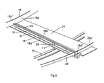
- Fig. 5 shows a part of an annular mould for casting of the platform 3.
- the annular mould comprises the inner ring 16 of a metal material.
- the inner ring 16 is adapted to define an inner circular substantially vertical wall surface 16a of the annular platform.
- the annular mould comprises an outer ring 23 of a metal material.
- the outer ring 23 is adapted to define an outer circular substantially vertical wall surface 23a of the annular mould.
- One rib form 18 with reinforcing elements 21, 22 has been mounted between the inner ring 16 and the outer ring 23.
- An upper portion of the flat steel plate 11 extends through the opening 20 of the rib form 18 and into the cavity 19.
- a suitable number of such rib form 18 are adapted to be mounted with substantially equal intervals around the annular mould.
- plane shuttering panels 24 are arranged in the spaces between the plane upper surfaces 18a', 18b' of adjacent rib forms 18. The shuttering panels 24 and the forms 18 define together the bottom surface of the annular mould.
- a method for manufacturing of the platform 3 can be performed as followed.
- the inner ring 16 and the outer ring 23 are arranged in mutually defined positions in relation to each other.
- the rings 16, 23 are arranged on a suitable level above the circular rail member 10.
- a plurality of rib form 18 are mounted between the inner ring 16 and the outer ring 23 such that adjacent rib forms 18 are mounted at equal distances from each other.
- Each rib form 18 is attached to the inner ring 16 by means of a bolt extending through corresponding holes in the connecting plate 18c" of the rib form and the inner ring 16. This bolt also extends into the inner tubular end element of the reinforcing element 22 for attachment of the reinforcing element 22 to the inner ring 16.
- Each rib form 18 is attached to the outer ring 23 by means of a bolt extending through corresponding holes in the connecting plate 18d" of the rib form 18 and the outer ring 23. This bolt also extends into the outer tubular end element of the reinforcing element 22 for attachment of the reinforcing element 22 to the outer ring 23.
- First reinforcing elements 21 are mounted in the cavities 19 of the respective rib forms 18 by means of bolts extending through corresponding holes in the wall elements 18c', 18d' and the tubular end elements of the reinforcing element 21.
- Flat steel plates 11 are connected to the first reinforcing element 21 and the second reinforcing element 22 by welding in the respective rib forms 18.
- a lower part of the flat steel plates 11 are welded to an upper part of the circular rail member 10.
- the plane shuttering panels 24 are arranged in the spaces between the plane upper surfaces 18a', 18b' of adjacent rib forms 18. Thereby, the annular mould is constructed.
- the shuttering panels 24 and the rib forms 18 define together the bottom surface of the annular mould, the inner ring 16 defines an inner circular vertical wall surface of the annular mould and the outer ring 23 defines an outer circular vertical wall surface of the annular mould.
- a flowable cementitious material is supplied to the annular mould in a quantity such that the annular mould is filled up.
- the rib forms 18 and the shuttering panels 24 are removed.
- a platform 3 is now manufactured in the form of an integral structure which comprises a poured annular body of cementitious material with embedded reinforcing elements 21, 22 and rings 16, 23 defining the inner and outer periphery surfaces of the platform 3.
- the platform 3 has a lower surface 3b comprising areas with a substantially plane surface 3c and areas comprising protruding ribs 3d. Both the ribs 3d and the reinforcing elements 21, 22 has an extension in a radial direction of the annular platform 3.
- the annular platform 3 will be stiffer in a radial direction than in a direction along its circular extension.
- the inner ring 16 has an upper edge portion located at a higher level then the upper edge portion of the outer ring 23.
- the upper surface 3a of the annular platform 3 obtains an inner circumference edge 3a' located at a higher level then the outer circumference edge 3a".
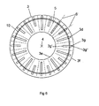
- Fig 6 shows a view from the underside of an alternative annular platform 3.
- the platform 3 comprises alternating long ribs 3d and short ribs 3g arranged at substantially equal distances from each other on the underside of the annular platform 3.
- the short ribs 3g has a substantially plane end surface 3g' located at a relatively large distance from the inner radial surface 3e of the platform and a substantially plane end surface 3g" located in the vicinity of the outer radial surface 3f of the platform.
- the circular rail member 10 is rigidly connected to both the long ribs 3d and short ribs 3g on the underside of the platform 3.
- Each of the milking stalls 6 can be divided in two equal halves by vertical planes 6' having an extension through a centre of the respective milking stalls 6.
- the long rib 3d or a short rib 3g are arranged in positions on the underside of the platform such that each of said vertical planes 6' has an extension through a long rib 3d or a short rib 3g.
Landscapes
- Life Sciences & Earth Sciences (AREA)
- Environmental Sciences (AREA)
- Zoology (AREA)
- Animal Husbandry (AREA)
- Biodiversity & Conservation Biology (AREA)
- Manufacturing Of Tubular Articles Or Embedded Moulded Articles (AREA)
- Piles And Underground Anchors (AREA)
- Housing For Livestock And Birds (AREA)
- Structures Of Non-Positive Displacement Pumps (AREA)
- Wind Motors (AREA)
- Joining Of Building Structures In Genera (AREA)
Claims (13)
- Plate-forme rotative annulaire (3) pour salle de traite, dans laquelle la plate-forme (3) est formée en un matériau cimentaire, caractérisée en ce que la plate-forme sur une face inférieure comprend au moins une partie de renforcement saillante (3d) formée en un matériau cimentaire, dans laquelle ladite partie de renforcement saillante (3d) présente une forme allongée sur la face inférieure de la plate-forme (3) et dans laquelle la plate-forme comprend une pluralité de ces parties de renforcement saillantes (3d, 3g) disposées dans différentes positions sur la face inférieure de la plate-forme (3).
- Plate-forme selon la revendication 1, caractérisée en ce qu'au moins deux des éléments saillants allongés (3d, 3g) présentent différentes extensions.
- Plate-forme selon la revendication 1 ou 2, caractérisée en ce que ladite partie de renforcement saillante (3d) présente une extension dans une direction essentiellement radiale sur la face inférieure de la plate-forme annulaire (3).
- Plate-forme selon la revendication 3, caractérisée en ce que des parties de renforcement saillantes (3d) adjacentes sont disposées à une distance essentiellement égale l'une de l'autre sur la face inférieure de la plate-forme (3).
- Plate-forme selon l'une quelconque des revendications précédentes, caractérisée en ce que la au moins une partie de renforcement saillante (3d) présente une surface d'extrémité (3d') essentiellement plane située à proximité d'une surface radiale intérieure (3e) de la plate-forme annulaire (3).
- Plate-forme selon l'une quelconque des revendications précédentes, caractérisée en ce que la au moins une partie de renforcement saillante (3d) présente une surface d'extrémité (3d") essentiellement plane située à proximité d'une surface radiale extérieure (3f) de la plate-forme annulaire (3).
- Plate-forme selon l'une quelconque des revendications précédentes, caractérisée en ce que la plate-forme (3) comprend au moins un élément de connexion (11) constituant une connexion essentiellement rigide entre la plate-forme (3) et un élément de rail circulaire (10) disposé sur une face inférieure de la plate-forme (3).
- Plate-forme selon la revendication 7, caractérisée en ce que ledit élément de connexion (11) constitue une connexion entre la partie de renforcement saillante (3d) de la plate-forme et l'élément de rail circulaire (10).
- Plate-forme selon la revendication 7 ou 8, caractérisée en ce que ledit élément de connexion (11) est connecté à la plate-forme (3) au moyen d'une partie d'extrémité supérieure coulée dans le matériau cimentaire de la plate-forme (3).
- Plate-forme selon l'une quelconque des revendications précédentes, caractérisée en ce que la plate-forme (3) comprend au moins un élément de renforcement (21, 22) coulé dans le matériau cimentaire.
- Plate-forme selon l'une quelconque des revendications précédentes, caractérisée en ce que la partie de renforcement saillante (3d) comprend au moins un élément de renforcement (21) coulé dans le matériau cimentaire.
- Plate-forme selon l'une quelconque des revendications précédentes, caractérisée en ce que la plate-forme annulaire (3) comprend un anneau intérieur (16) en un matériau métallique formant une surface radiale intérieure (3e) de la plate-forme (3).
- Plate-forme selon l'une quelconque des revendications précédentes, caractérisée en ce que la plate-forme annulaire (3) comprend un anneau extérieur (23) en un matériau métallique formant une surface radiale extérieure (3f) de la plate-forme (3).
Applications Claiming Priority (2)
| Application Number | Priority Date | Filing Date | Title |
|---|---|---|---|
| SE0601415 | 2006-06-28 | ||
| PCT/SE2007/050325 WO2008002253A1 (fr) | 2006-06-28 | 2007-05-10 | Plate-forme rotative annulaire pour salle de traite, moule et procédé de fabrication d'une telle plate-forme |
Publications (3)
| Publication Number | Publication Date |
|---|---|
| EP2037731A1 EP2037731A1 (fr) | 2009-03-25 |
| EP2037731A4 EP2037731A4 (fr) | 2011-08-31 |
| EP2037731B1 true EP2037731B1 (fr) | 2013-04-10 |
Family
ID=38845898
Family Applications (1)
| Application Number | Title | Priority Date | Filing Date |
|---|---|---|---|
| EP07748486.3A Active EP2037731B1 (fr) | 2006-06-28 | 2007-05-10 | Plate-forme rotative annulaire pour salle de traite |
Country Status (6)
| Country | Link |
|---|---|
| US (1) | US8051801B2 (fr) |
| EP (1) | EP2037731B1 (fr) |
| CN (1) | CN101478871B (fr) |
| AU (1) | AU2007265740B2 (fr) |
| NZ (1) | NZ573659A (fr) |
| WO (1) | WO2008002253A1 (fr) |
Cited By (1)
| Publication number | Priority date | Publication date | Assignee | Title |
|---|---|---|---|---|
| CN102628322A (zh) * | 2012-03-15 | 2012-08-08 | 郝小鲁 | 碰对轮盘房 |
Families Citing this family (8)
| Publication number | Priority date | Publication date | Assignee | Title |
|---|---|---|---|---|
| US20120012058A1 (en) * | 2008-11-03 | 2012-01-19 | Joshua Wayne Janmaat | Infusion moulded platforms and components thereof |
| EP2348823B1 (fr) * | 2008-11-03 | 2021-01-20 | Waikato Milking Systems LP | Plates-formes rotatives |
| US9357749B2 (en) * | 2010-01-29 | 2016-06-07 | Gea Houle Inc. | Rotary milking station, kit for assembling the same, and methods of assembling and operating associated thereto |
| US20110308467A1 (en) * | 2010-06-18 | 2011-12-22 | Eckhardt Shawn R | System and Method for Controlling the Speed of a Rotary Milking Platform Using a Rotary Encoder |
| DE102012110501A1 (de) * | 2012-03-14 | 2013-09-19 | Gea Farm Technologies Gmbh | Platzteiler einer Melkstandanordnung und Melkstandanordnung |
| CA2887408C (fr) * | 2012-11-07 | 2020-09-29 | Delaval Holding Ab | Rouleau d'amenagement de support destine a une plate-forme de traite rotative |
| EP3681273A1 (fr) * | 2017-09-12 | 2020-07-22 | Dairymaster | Élément de support et procédé de support d'une poutre allongée, et plate-forme rotative |
| US12493286B2 (en) | 2020-05-20 | 2025-12-09 | Delaval Holding Ab | System and computer-implemented method for controlling a rotary milking parlor arrangement and computer program |
Family Cites Families (35)
| Publication number | Priority date | Publication date | Assignee | Title |
|---|---|---|---|---|
| US921626A (en) * | 1909-05-11 | Walther Raster | Reinforced concrete construction. | |
| US694577A (en) * | 1901-07-13 | 1902-03-04 | Ernest L Ransome | Reinforced concrete construction. |
| US1968564A (en) * | 1928-03-17 | 1934-07-31 | Walker Gordon Lab Company Inc | Milking apparatus |
| US1787152A (en) * | 1928-03-17 | 1930-12-30 | Laval Separator Co De | Cow-milking apparatus |
| US1871318A (en) * | 1929-01-30 | 1932-08-09 | Richard F Greenwood | Precast concrete structural unit |
| US1977864A (en) * | 1931-05-18 | 1934-10-23 | George A Smith Turntable Corp | Vehicle turntable |
| US1969634A (en) * | 1932-04-25 | 1934-08-07 | James D Acuff | Turntable |
| US2035007A (en) * | 1933-08-21 | 1936-03-24 | Workman James Minor | Concrete construction |
| US2558580A (en) * | 1945-01-23 | 1951-06-26 | Edmund S Pomykala | Underground storage tank |
| US2859504A (en) * | 1952-06-11 | 1958-11-11 | Francis X Crowley | Process of making prestressed concrete structures |
| US3153303A (en) * | 1959-03-20 | 1964-10-20 | James E Wheeler | Building construction |
| US3103912A (en) * | 1962-01-02 | 1963-09-17 | Roto Stalls Corp | Rotating milking and housing system |
| GB1240797A (en) * | 1968-03-09 | 1971-07-28 | Vanich F | Improvements in and relating to the construction of elevated houses |
| US3710526A (en) * | 1970-12-17 | 1973-01-16 | C Parks | Annular compression beam |
| US3828500A (en) * | 1971-07-30 | 1974-08-13 | J Chancey | Reinforced concrete construction |
| US3910452A (en) * | 1972-12-01 | 1975-10-07 | Sandborn Edmund | Floating cover for a storage tank |
| US3934551A (en) * | 1974-09-09 | 1976-01-27 | Kevin John Sulzberger | Milking system |
| US4716837A (en) * | 1986-09-19 | 1988-01-05 | Valencia Alfred E | Automobile turntable |
| US4778144A (en) * | 1987-01-23 | 1988-10-18 | Gregory R Kirk | Concrete slab and beam forming system |
| US4979869A (en) * | 1987-10-06 | 1990-12-25 | Outboard Marine Corporation | Method for storing boats in a storage building |
| US5086704A (en) * | 1990-09-17 | 1992-02-11 | Michael E. Mueller | Motor vehicle turntable |
| US5755160A (en) * | 1994-07-21 | 1998-05-26 | Blufordcraving; Charles Nathaniel | Rotating floor for motor vehicles |
| NZ270905A (en) * | 1995-04-10 | 1996-01-26 | John Murray Bowers | Entry and exit arrangement for animals using a rotary milking platform |
| NZ270955A (en) | 1995-04-19 | 1996-11-26 | Anderson & Rooney Engineering | Construction of concrete-top rotary milking platform: steel framework supports shuttering |
| NZ270997A (en) * | 1995-04-27 | 1995-12-21 | John Murray Bowers | Method of constructing an elevated annular concrete slab for a milking shed |
| US6050219A (en) * | 1996-04-04 | 2000-04-18 | Van Der Lely; Cornelis | Apparatus for milking animals |
| AU744955B2 (en) * | 1998-05-22 | 2002-03-07 | Delaval Inc. | Method of construction of elevated annular platform |
| JP2001227064A (ja) | 2000-02-17 | 2001-08-24 | Taisei Corp | 可変空間を有する居室空間 |
| US6843203B2 (en) * | 2000-03-17 | 2005-01-18 | Delaval Holding Ab | Device for at least one milking stall and a parlor comprising a plurality of milking stalls |
| US20020033138A1 (en) * | 2000-09-17 | 2002-03-21 | Eyal Brayer | Animal-milking system useful for milking large herds |
| NZ507546A (en) * | 2000-12-20 | 2001-03-30 | Laval Ltd De | Frame for rotary milking platform to which can be attached hosing. |
| US6470640B2 (en) * | 2001-10-26 | 2002-10-29 | Kalman Floor Company | Reinforced shrinkage compensating concrete slab structure |
| AUPS302202A0 (en) * | 2002-06-19 | 2002-07-11 | John Austin Constructions Pty Ltd | Improvements relating to milking platforms |
| US6814027B2 (en) * | 2002-09-12 | 2004-11-09 | Westfaliasurge, Inc. | Milker unit detacher for rotary milking parlor |
| SE0203871D0 (sv) * | 2002-12-20 | 2002-12-20 | Delaval Holding Ab | Milking Devices |
-
2007
- 2007-05-10 NZ NZ573659A patent/NZ573659A/en unknown
- 2007-05-10 US US12/306,786 patent/US8051801B2/en not_active Expired - Fee Related
- 2007-05-10 WO PCT/SE2007/050325 patent/WO2008002253A1/fr not_active Ceased
- 2007-05-10 EP EP07748486.3A patent/EP2037731B1/fr active Active
- 2007-05-10 AU AU2007265740A patent/AU2007265740B2/en not_active Ceased
- 2007-05-10 CN CN2007800246014A patent/CN101478871B/zh active Active
Cited By (1)
| Publication number | Priority date | Publication date | Assignee | Title |
|---|---|---|---|---|
| CN102628322A (zh) * | 2012-03-15 | 2012-08-08 | 郝小鲁 | 碰对轮盘房 |
Also Published As
| Publication number | Publication date |
|---|---|
| CN101478871B (zh) | 2011-11-16 |
| AU2007265740B2 (en) | 2012-09-06 |
| AU2007265740A1 (en) | 2008-01-03 |
| US8051801B2 (en) | 2011-11-08 |
| WO2008002253A1 (fr) | 2008-01-03 |
| CN101478871A (zh) | 2009-07-08 |
| NZ573659A (en) | 2012-03-30 |
| US20090183687A1 (en) | 2009-07-23 |
| EP2037731A1 (fr) | 2009-03-25 |
| EP2037731A4 (fr) | 2011-08-31 |
Similar Documents
| Publication | Publication Date | Title |
|---|---|---|
| EP2037731B1 (fr) | Plate-forme rotative annulaire pour salle de traite | |
| JP2012527549A5 (fr) | ||
| JP2011510844A (ja) | 中空コンクリート要素の製造方法 | |
| CN108086687B (zh) | 楼层内混凝土布料系统及其施工方法 | |
| US20090266301A1 (en) | Rotary parlour for milking of animals | |
| JP2018076652A (ja) | 壁体の構造と構築方法、壁体構築用の鉄筋ユニットと連結金具 | |
| US20090183686A1 (en) | Rotary parlour for milking of animals | |
| KR101730569B1 (ko) | 하이브리드 보 및 그 시공방법 | |
| JP2883898B2 (ja) | Pc柱及びpc柱構法 | |
| KR20060006112A (ko) | 강관파일의 두부보강장치 | |
| JP2019143392A (ja) | 梁部材複合体及び床構造 | |
| KR102437398B1 (ko) | 시공성이 용이한 일체형 슬라브 유로폼 시스템 | |
| KR200271490Y1 (ko) | 콘크리트 타설기 | |
| US20240365747A1 (en) | Platform for a rotary milking parlor of light-weight construction and containing carbon concrete | |
| WO2010036129A1 (fr) | Systeme de crochets pour unites de construction a base de ciment | |
| CN217537293U (zh) | 一种预制构件及装配式管柱 | |
| NZ260603A (en) | Reinforced concrete moulded section for floor of rotary milking shed | |
| KR20090001291A (ko) | 바닥면으로 유로폼의 낙하를 방지하는 드롭 다운 지지장치 | |
| KR101979745B1 (ko) | 바닥콘크리트 거푸집 지지장치 | |
| KR200485889Y1 (ko) | 건물 청소용 로프고정장치 | |
| JP2759559B2 (ja) | 地下構築物の構築方法 | |
| JPH06306976A (ja) | 配管スリーブ固定金具 | |
| KR20060101955A (ko) | 고층 건물용 콘크리트 분배기 | |
| WO2006047754A2 (fr) | Systeme a structures de beton et dispositif de precoulage de structures de beton | |
| KR20200031017A (ko) | 형틀 없는 콘크리트공법 및 철근 콘크리트 구조체 |
Legal Events
| Date | Code | Title | Description |
|---|---|---|---|
| PUAI | Public reference made under article 153(3) epc to a published international application that has entered the european phase |
Free format text: ORIGINAL CODE: 0009012 |
|
| 17P | Request for examination filed |
Effective date: 20090127 |
|
| AK | Designated contracting states |
Kind code of ref document: A1 Designated state(s): AT BE BG CH CY CZ DE DK EE ES FI FR GB GR HU IE IS IT LI LT LU LV MC MT NL PL PT RO SE SI SK TR |
|
| AX | Request for extension of the european patent |
Extension state: AL BA HR MK RS |
|
| A4 | Supplementary search report drawn up and despatched |
Effective date: 20110803 |
|
| RIC1 | Information provided on ipc code assigned before grant |
Ipc: A01K 1/12 20060101AFI20110728BHEP Ipc: E04B 5/32 20060101ALI20110728BHEP Ipc: E04B 5/43 20060101ALI20110728BHEP Ipc: E04B 1/346 20060101ALI20110728BHEP |
|
| DAX | Request for extension of the european patent (deleted) | ||
| GRAP | Despatch of communication of intention to grant a patent |
Free format text: ORIGINAL CODE: EPIDOSNIGR1 |
|
| GRAS | Grant fee paid |
Free format text: ORIGINAL CODE: EPIDOSNIGR3 |
|
| GRAA | (expected) grant |
Free format text: ORIGINAL CODE: 0009210 |
|
| AK | Designated contracting states |
Kind code of ref document: B1 Designated state(s): AT BE BG CH CY CZ DE DK EE ES FI FR GB GR HU IE IS IT LI LT LU LV MC MT NL PL PT RO SE SI SK TR |
|
| REG | Reference to a national code |
Ref country code: GB Ref legal event code: FG4D |
|
| REG | Reference to a national code |
Ref country code: CH Ref legal event code: EP Ref country code: AT Ref legal event code: REF Ref document number: 605431 Country of ref document: AT Kind code of ref document: T Effective date: 20130415 |
|
| REG | Reference to a national code |
Ref country code: IE Ref legal event code: FG4D |
|
| REG | Reference to a national code |
Ref country code: DE Ref legal event code: R096 Ref document number: 602007029669 Country of ref document: DE Effective date: 20130606 |
|
| PG25 | Lapsed in a contracting state [announced via postgrant information from national office to epo] |
Ref country code: SI Free format text: LAPSE BECAUSE OF FAILURE TO SUBMIT A TRANSLATION OF THE DESCRIPTION OR TO PAY THE FEE WITHIN THE PRESCRIBED TIME-LIMIT Effective date: 20130410 |
|
| REG | Reference to a national code |
Ref country code: NL Ref legal event code: T3 |
|
| REG | Reference to a national code |
Ref country code: AT Ref legal event code: MK05 Ref document number: 605431 Country of ref document: AT Kind code of ref document: T Effective date: 20130410 |
|
| REG | Reference to a national code |
Ref country code: LT Ref legal event code: MG4D |
|
| PG25 | Lapsed in a contracting state [announced via postgrant information from national office to epo] |
Ref country code: IS Free format text: LAPSE BECAUSE OF FAILURE TO SUBMIT A TRANSLATION OF THE DESCRIPTION OR TO PAY THE FEE WITHIN THE PRESCRIBED TIME-LIMIT Effective date: 20130810 Ref country code: AT Free format text: LAPSE BECAUSE OF FAILURE TO SUBMIT A TRANSLATION OF THE DESCRIPTION OR TO PAY THE FEE WITHIN THE PRESCRIBED TIME-LIMIT Effective date: 20130410 Ref country code: ES Free format text: LAPSE BECAUSE OF FAILURE TO SUBMIT A TRANSLATION OF THE DESCRIPTION OR TO PAY THE FEE WITHIN THE PRESCRIBED TIME-LIMIT Effective date: 20130721 Ref country code: SE Free format text: LAPSE BECAUSE OF FAILURE TO SUBMIT A TRANSLATION OF THE DESCRIPTION OR TO PAY THE FEE WITHIN THE PRESCRIBED TIME-LIMIT Effective date: 20130410 Ref country code: BE Free format text: LAPSE BECAUSE OF FAILURE TO SUBMIT A TRANSLATION OF THE DESCRIPTION OR TO PAY THE FEE WITHIN THE PRESCRIBED TIME-LIMIT Effective date: 20130410 Ref country code: LT Free format text: LAPSE BECAUSE OF FAILURE TO SUBMIT A TRANSLATION OF THE DESCRIPTION OR TO PAY THE FEE WITHIN THE PRESCRIBED TIME-LIMIT Effective date: 20130410 Ref country code: PT Free format text: LAPSE BECAUSE OF FAILURE TO SUBMIT A TRANSLATION OF THE DESCRIPTION OR TO PAY THE FEE WITHIN THE PRESCRIBED TIME-LIMIT Effective date: 20130812 Ref country code: GR Free format text: LAPSE BECAUSE OF FAILURE TO SUBMIT A TRANSLATION OF THE DESCRIPTION OR TO PAY THE FEE WITHIN THE PRESCRIBED TIME-LIMIT Effective date: 20130711 Ref country code: FI Free format text: LAPSE BECAUSE OF FAILURE TO SUBMIT A TRANSLATION OF THE DESCRIPTION OR TO PAY THE FEE WITHIN THE PRESCRIBED TIME-LIMIT Effective date: 20130410 |
|
| PG25 | Lapsed in a contracting state [announced via postgrant information from national office to epo] |
Ref country code: PL Free format text: LAPSE BECAUSE OF FAILURE TO SUBMIT A TRANSLATION OF THE DESCRIPTION OR TO PAY THE FEE WITHIN THE PRESCRIBED TIME-LIMIT Effective date: 20130410 Ref country code: CY Free format text: LAPSE BECAUSE OF FAILURE TO SUBMIT A TRANSLATION OF THE DESCRIPTION OR TO PAY THE FEE WITHIN THE PRESCRIBED TIME-LIMIT Effective date: 20130410 Ref country code: LV Free format text: LAPSE BECAUSE OF FAILURE TO SUBMIT A TRANSLATION OF THE DESCRIPTION OR TO PAY THE FEE WITHIN THE PRESCRIBED TIME-LIMIT Effective date: 20130410 Ref country code: BG Free format text: LAPSE BECAUSE OF FAILURE TO SUBMIT A TRANSLATION OF THE DESCRIPTION OR TO PAY THE FEE WITHIN THE PRESCRIBED TIME-LIMIT Effective date: 20130710 |
|
| REG | Reference to a national code |
Ref country code: CH Ref legal event code: PL |
|
| PG25 | Lapsed in a contracting state [announced via postgrant information from national office to epo] |
Ref country code: MC Free format text: LAPSE BECAUSE OF FAILURE TO SUBMIT A TRANSLATION OF THE DESCRIPTION OR TO PAY THE FEE WITHIN THE PRESCRIBED TIME-LIMIT Effective date: 20130410 Ref country code: CZ Free format text: LAPSE BECAUSE OF FAILURE TO SUBMIT A TRANSLATION OF THE DESCRIPTION OR TO PAY THE FEE WITHIN THE PRESCRIBED TIME-LIMIT Effective date: 20130410 Ref country code: EE Free format text: LAPSE BECAUSE OF FAILURE TO SUBMIT A TRANSLATION OF THE DESCRIPTION OR TO PAY THE FEE WITHIN THE PRESCRIBED TIME-LIMIT Effective date: 20130410 Ref country code: DK Free format text: LAPSE BECAUSE OF FAILURE TO SUBMIT A TRANSLATION OF THE DESCRIPTION OR TO PAY THE FEE WITHIN THE PRESCRIBED TIME-LIMIT Effective date: 20130410 Ref country code: SK Free format text: LAPSE BECAUSE OF FAILURE TO SUBMIT A TRANSLATION OF THE DESCRIPTION OR TO PAY THE FEE WITHIN THE PRESCRIBED TIME-LIMIT Effective date: 20130410 Ref country code: CH Free format text: LAPSE BECAUSE OF NON-PAYMENT OF DUE FEES Effective date: 20130531 Ref country code: LI Free format text: LAPSE BECAUSE OF NON-PAYMENT OF DUE FEES Effective date: 20130531 |
|
| PLBE | No opposition filed within time limit |
Free format text: ORIGINAL CODE: 0009261 |
|
| STAA | Information on the status of an ep patent application or granted ep patent |
Free format text: STATUS: NO OPPOSITION FILED WITHIN TIME LIMIT |
|
| REG | Reference to a national code |
Ref country code: IE Ref legal event code: MM4A |
|
| PG25 | Lapsed in a contracting state [announced via postgrant information from national office to epo] |
Ref country code: IT Free format text: LAPSE BECAUSE OF FAILURE TO SUBMIT A TRANSLATION OF THE DESCRIPTION OR TO PAY THE FEE WITHIN THE PRESCRIBED TIME-LIMIT Effective date: 20130410 Ref country code: RO Free format text: LAPSE BECAUSE OF FAILURE TO SUBMIT A TRANSLATION OF THE DESCRIPTION OR TO PAY THE FEE WITHIN THE PRESCRIBED TIME-LIMIT Effective date: 20130410 |
|
| 26N | No opposition filed |
Effective date: 20140113 |
|
| REG | Reference to a national code |
Ref country code: DE Ref legal event code: R097 Ref document number: 602007029669 Country of ref document: DE Effective date: 20140113 |
|
| PG25 | Lapsed in a contracting state [announced via postgrant information from national office to epo] |
Ref country code: IE Free format text: LAPSE BECAUSE OF NON-PAYMENT OF DUE FEES Effective date: 20130510 |
|
| PG25 | Lapsed in a contracting state [announced via postgrant information from national office to epo] |
Ref country code: MT Free format text: LAPSE BECAUSE OF FAILURE TO SUBMIT A TRANSLATION OF THE DESCRIPTION OR TO PAY THE FEE WITHIN THE PRESCRIBED TIME-LIMIT Effective date: 20130410 |
|
| PG25 | Lapsed in a contracting state [announced via postgrant information from national office to epo] |
Ref country code: TR Free format text: LAPSE BECAUSE OF FAILURE TO SUBMIT A TRANSLATION OF THE DESCRIPTION OR TO PAY THE FEE WITHIN THE PRESCRIBED TIME-LIMIT Effective date: 20130410 |
|
| PG25 | Lapsed in a contracting state [announced via postgrant information from national office to epo] |
Ref country code: HU Free format text: LAPSE BECAUSE OF FAILURE TO SUBMIT A TRANSLATION OF THE DESCRIPTION OR TO PAY THE FEE WITHIN THE PRESCRIBED TIME-LIMIT; INVALID AB INITIO Effective date: 20070510 Ref country code: LU Free format text: LAPSE BECAUSE OF NON-PAYMENT OF DUE FEES Effective date: 20130510 |
|
| REG | Reference to a national code |
Ref country code: FR Ref legal event code: PLFP Year of fee payment: 10 |
|
| REG | Reference to a national code |
Ref country code: FR Ref legal event code: PLFP Year of fee payment: 11 |
|
| REG | Reference to a national code |
Ref country code: FR Ref legal event code: PLFP Year of fee payment: 12 |
|
| PGFP | Annual fee paid to national office [announced via postgrant information from national office to epo] |
Ref country code: NL Payment date: 20220420 Year of fee payment: 16 |
|
| PGFP | Annual fee paid to national office [announced via postgrant information from national office to epo] |
Ref country code: FR Payment date: 20220422 Year of fee payment: 16 |
|
| REG | Reference to a national code |
Ref country code: NL Ref legal event code: MM Effective date: 20230601 |
|
| PG25 | Lapsed in a contracting state [announced via postgrant information from national office to epo] |
Ref country code: NL Free format text: LAPSE BECAUSE OF NON-PAYMENT OF DUE FEES Effective date: 20230601 |
|
| PG25 | Lapsed in a contracting state [announced via postgrant information from national office to epo] |
Ref country code: FR Free format text: LAPSE BECAUSE OF NON-PAYMENT OF DUE FEES Effective date: 20230531 |
|
| PGFP | Annual fee paid to national office [announced via postgrant information from national office to epo] |
Ref country code: DE Payment date: 20250402 Year of fee payment: 19 |
|
| PGFP | Annual fee paid to national office [announced via postgrant information from national office to epo] |
Ref country code: GB Payment date: 20250401 Year of fee payment: 19 |