EP2039017B1 - Ausnutzung des restfrequenzoffsets - Google Patents
Ausnutzung des restfrequenzoffsets Download PDFInfo
- Publication number
- EP2039017B1 EP2039017B1 EP07765420A EP07765420A EP2039017B1 EP 2039017 B1 EP2039017 B1 EP 2039017B1 EP 07765420 A EP07765420 A EP 07765420A EP 07765420 A EP07765420 A EP 07765420A EP 2039017 B1 EP2039017 B1 EP 2039017B1
- Authority
- EP
- European Patent Office
- Prior art keywords
- residual frequency
- err
- res
- function
- frequency offsets
- Prior art date
- Legal status (The legal status is an assumption and is not a legal conclusion. Google has not performed a legal analysis and makes no representation as to the accuracy of the status listed.)
- Not-in-force
Links
- 238000004891 communication Methods 0.000 claims abstract description 30
- 230000002596 correlated effect Effects 0.000 claims abstract description 16
- 238000000034 method Methods 0.000 claims description 19
- 230000004044 response Effects 0.000 claims description 12
- 230000001276 controlling effect Effects 0.000 claims 2
- 230000003044 adaptive effect Effects 0.000 abstract description 22
- 230000006870 function Effects 0.000 description 12
- 238000010586 diagram Methods 0.000 description 6
- 238000012935 Averaging Methods 0.000 description 3
- 238000012937 correction Methods 0.000 description 3
- 230000000875 corresponding effect Effects 0.000 description 2
- 238000013461 design Methods 0.000 description 2
- 238000001514 detection method Methods 0.000 description 2
- 238000002474 experimental method Methods 0.000 description 2
- 238000005562 fading Methods 0.000 description 2
- 238000012545 processing Methods 0.000 description 2
- 230000009286 beneficial effect Effects 0.000 description 1
- 230000001413 cellular effect Effects 0.000 description 1
- 230000000295 complement effect Effects 0.000 description 1
- 230000021615 conjugation Effects 0.000 description 1
- 239000013078 crystal Substances 0.000 description 1
- 230000001627 detrimental effect Effects 0.000 description 1
- 230000000694 effects Effects 0.000 description 1
- 230000003287 optical effect Effects 0.000 description 1
- 239000013307 optical fiber Substances 0.000 description 1
- 239000004065 semiconductor Substances 0.000 description 1
- 238000001228 spectrum Methods 0.000 description 1
- 230000007480 spreading Effects 0.000 description 1
Images
Classifications
-
- H—ELECTRICITY
- H04—ELECTRIC COMMUNICATION TECHNIQUE
- H04B—TRANSMISSION
- H04B1/00—Details of transmission systems, not covered by a single one of groups H04B3/00 - H04B13/00; Details of transmission systems not characterised by the medium used for transmission
- H04B1/69—Spread spectrum techniques
- H04B1/707—Spread spectrum techniques using direct sequence modulation
- H04B1/7097—Interference-related aspects
- H04B1/711—Interference-related aspects the interference being multi-path interference
- H04B1/7115—Constructive combining of multi-path signals, i.e. RAKE receivers
- H04B1/7117—Selection, re-selection, allocation or re-allocation of paths to fingers, e.g. timing offset control of allocated fingers
-
- H—ELECTRICITY
- H04—ELECTRIC COMMUNICATION TECHNIQUE
- H04B—TRANSMISSION
- H04B1/00—Details of transmission systems, not covered by a single one of groups H04B3/00 - H04B13/00; Details of transmission systems not characterised by the medium used for transmission
- H04B1/69—Spread spectrum techniques
- H04B1/707—Spread spectrum techniques using direct sequence modulation
- H04B1/7073—Synchronisation aspects
- H04B1/7087—Carrier synchronisation aspects
-
- H—ELECTRICITY
- H04—ELECTRIC COMMUNICATION TECHNIQUE
- H04B—TRANSMISSION
- H04B2201/00—Indexing scheme relating to details of transmission systems not covered by a single group of H04B3/00 - H04B13/00
- H04B2201/69—Orthogonal indexing scheme relating to spread spectrum techniques in general
- H04B2201/707—Orthogonal indexing scheme relating to spread spectrum techniques in general relating to direct sequence modulation
- H04B2201/7097—Direct sequence modulation interference
- H04B2201/709727—GRAKE type RAKE receivers
-
- H—ELECTRICITY
- H04—ELECTRIC COMMUNICATION TECHNIQUE
- H04L—TRANSMISSION OF DIGITAL INFORMATION, e.g. TELEGRAPHIC COMMUNICATION
- H04L27/00—Modulated-carrier systems
- H04L27/0014—Carrier regulation
- H04L2027/0044—Control loops for carrier regulation
- H04L2027/0053—Closed loops
- H04L2027/0055—Closed loops single phase
-
- H—ELECTRICITY
- H04—ELECTRIC COMMUNICATION TECHNIQUE
- H04L—TRANSMISSION OF DIGITAL INFORMATION, e.g. TELEGRAPHIC COMMUNICATION
- H04L27/00—Modulated-carrier systems
- H04L27/0014—Carrier regulation
- H04L2027/0044—Control loops for carrier regulation
- H04L2027/0063—Elements of loops
- H04L2027/0065—Frequency error detectors
Definitions
- This invention relates to mobile wireless communication systems.
- each device e.g., a user equipment (UE), a base station (BS), etc.
- a local oscillator (LO) that defines a local time reference. It is important for the LOs of devices communicating with each other to be aligned as precisely as possible. If two devices' LOs are not aligned, their time references drift in relation to each other, which can result in the devices' being no longer capable of receiving information properly from each other and in loss of the connection.
- LO alignment is particularly important to wireless communication systems like wideband code division multiple access (WCDMA) mobile telephone systems and other digital mobile telephone systems.
- WCDMA wideband code division multiple access
- a typical receiver uses automatic frequency control (AFC) to adjust its LO so that it aligns well with the LO(s) of the transmitter(s) to which it is connected.
- AFC automatic frequency control
- a WCDMA communication system uses direct-sequence spread-spectrum techniques.
- Pseudo-noise scrambling codes and orthogonal channelization codes separate BSs and physical communication channels, respectively, in the downlink (BS-to-UE) and uplink (UE-to-BS) directions.
- Scrambling and channelization codes are well known in the art, and WCDMA and other third-generation (3G) and future communication systems operate in accordance with standards promulgated by the Third Generation Partnership Project (3GPP).
- High-speed downlink (DL) packet access is an evolution of WCDMA communication systems that provides higher bit rates by using higher order modulation, multiple spreading codes, adaptive forward error correction (FEC), and DL-channel feedback information.
- the DL-channel feedback information is information sent by a UE to a BS through the uplink (UL) channel regarding the DL channel's quality.
- the cell providing HSDPA service is usually called the "serving" cell, and the serving cell uses the DL-channel feedback information to optimize the DL modulation and coding for throughput.
- AFC operation is almost never perfect, which is to say that there is almost always a non-zero frequency difference between the LOs of the transmitting and receiving devices even with AFC.
- the operation of a typical AFC involves studying communication-channel parameters over time and attempting to adjust an LO based on at least those parameters. For example, complex-valued estimates of the impulse response of the communication channel might be studied over time, and the adjustment of the LO may be done such that no rotation of the channel estimates is seen in the complex (or I-Q) plane. That kind of adjustment is based on the fact that rotation in the I-Q plane corresponds to relative frequency drift of the LOs, which in turn corresponds to relative time reference drift.
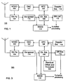
- FIG. 1 is a block diagram of an apparatus 100, which may be a portion of a receiver in a typical UE or BS, and depicts the operation of a typical AFC.
- a voltage-controller crystal oscillator (VCXO) 102 generates the LO signal used by a receiver front end (RX Fe) 104.
- the frequency of the LO signal produced by the VCXO 102 is responsive to a control signal f err generated by an AFC 106, and as illustrated, the control signal produced by the AFC 106 may be converted to an analog control voltage by a digital-to-analog converter (DAC) 107.
- the LO frequency set by the AFC 106 is called the "AFC frequency" in this application.
- FIG. 1 is a block diagram of an apparatus 100, which may be a portion of a receiver in a typical UE or BS, and depicts the operation of a typical AFC.
- a voltage-controller crystal oscillator (VCXO) 102 generates the
- the AFC 106 generates the control signal f err based on channel estimates ⁇ f produced by a channel estimator 108, which typically provides such estimates to other devices in the receiver, including for example a RAKE combiner 110 and a signal-to-interference ratio (SIR) estimator 112.
- the channel estimator 108 generates the channel estimates from correlated signals provided by a de-spreader 114, which generates the correlated signals from signals from the RX Fe 104. Correlated signals from the de-spreader 114 are selectively combined based on the channel estimates by the RAKE combiner 110.
- Channel estimation generally involves multiplying the correlated signals with the complex conjugates of known signals (or pilots), and possibly averaging the results over time.
- U.S. Patent Application Publication No. 2005/0105647 by Wilhelmsson et al. for "Channel Estimation by Adaptive Interpolation” describes channel estimation in a communication system using orthogonal frequency division multiplex.
- RAKE combining is described in, for example, John G. Proakis, "Digital Communications", 3rd ed., pp. 797-806. McGraw-Hill ; and U.S. Patent No. 6,922,434 by Wang et al. for "Apparatus and Methods for Finger Delay Selection in Rake Receivers". Signals from the RAKE combiner 110 and SIR estimator 112 are typically used in further processing operations carried out by the UE or other receiver.
- a typical AFC 106 periodically reports a single frequency error f err that is a weighted combination of frequency errors of respective de-spread fingers, although it will be understood that this is just one of many possible examples.
- One or more channel estimates ⁇ r are collected for each finger f during a given time period, e.g., during each of the successive time slots into which the received signal is organized.
- the frequency differences between the fingers, and thus the residual frequency offsets, due to Doppler shifts are usually not large, but in high-relative-velocity situations, the frequency differences and residual frequency offsets can be large enough to degrade receiver performance.
- channel estimation, power estimation, interference estimation, SIR estimation, relative channel gain estimation e.g., the difference between the common pilot channel (CPICH) and dedicated physical channel (DPCH) in a WCDMA communication system
- CPICH common pilot channel
- DPCH dedicated physical channel
- U.S. Patent 7443826 describes compensating for residual frequency offsets in a receiver chain.
- the compensation can include estimation of a residual frequency offset for each finger f err , f res , and frequency error correction (de-rotation) of received, de-spread symbols for each finger f or for each cell (transmitter).
- Such compensation can enhance receiver performance in high-velocity situations or when the LOs are not well aligned in frequency, but for a receiver to apply the compensation, a channel estimator having increased complexity is needed.
- the compensation itself can also introduce additional operations that must be carried out. The additional complexity of this compensation strategy is costly and thus can be undesirable.
- a receiver can include a Doppler-spread estimator 116 that is sometimes also used as a velocity estimator.
- a typical Doppler estimator applies either an argument- (or zero- ) crossing algorithm or a level-crossing algorithm, for example, to received signals.
- a variant of the argument-crossing algorithm counts the number of times that the complex channel estimate crosses either of the I and Q axes.
- the level-crossing algorithm counts the number of times the absolute value of the complex channel estimate crosses a given level.
- Estimates of the Doppler spread can be used to set operation mode and parameter values for various blocks in the receiver chain, e.g., the AFC 106, the RAKE combiner 110 (which may alternatively be a generalized RAKE or other type of RAKE receiver or signal equalizer), the SIR estimator 112, as well as an estimator of the relative channel gain (part of the further processing indicated generally in FIG. 1 ).
- the AFC 106 the RAKE combiner 110
- the SIR estimator 112 as well as an estimator of the relative channel gain (part of the further processing indicated generally in FIG. 1 ).
- Doppler estimation using a plurality of channel estimates and frequency offset estimates is known from EP-A-1 416 692 , which also discloses the use for mode control.
- a conventional Doppler estimator is a poor velocity estimator because the conventional Doppler estimator bases its estimates on the Rayleigh fading properties of the strongest signal paths, or de-spread fingers.
- the conventional Doppler estimator is inappropriate for situations having weak or no fading, e.g., line-of-sight (LOS) communication conditions where the strongest path is typically dominant and has a Ricean distribution.
- LOS line-of-sight
- those situations include passing close by a BS. It is thus desirable to be able to generate velocity estimates that avoid the problems of conventional Doppler estimators.
- the invention provides a method and an apparatus as defined in claims 1 and 7.
- the respective residual frequency offsets of the de-spread fingers are determined and used to improve receiver performance, particularly in high-velocity situations.
- f err , f res denote the respective residual frequency offset of a finger f , where f ⁇ F and F is, for example, the set of fingers involved in AFC operation.
- a function of f err , f res is used as a control signal or switch to select or turn on/off various algorithms implemented in the receiver, or in other words to determine an operating mode of the receiver.
- ⁇ f err , f res 1 F ⁇ f ⁇ F f err , f res which is a short-hand way to say that one uses the average of a set of residual frequency offsets as the control signal or switch.
- the performance of various receiver algorithms can be improved by an adaptive AFC that is described in more detail below.
- problems with using a Doppler estimate as a velocity estimate are overcome by a complementary velocity estimate based on the residual frequency offsets.
- Another way to reduce the additional complexity of the prior compensation strategy is to use the prior compensation strategy only when it is needed based on the residual frequency offsets as described in more detail below.
- the knowledge of the residual frequency offsets of the respective fingers can be used in several ways, three of which may be called adaptive AFC combining, improved velocity estimation, and adaptive residual frequency offset compensation. Each of these is described in more detail below.
- the inventor has appreciated that when there are large differences between the frequency errors of the respective fingers and the average frequency error, which is conventionally used to determine the AFC frequency, it can be beneficial to let the AFC report the frequency error of one of the fingers instead of the average value. This is so because if the average value is reported, there is a risk that none of the fingers has a small residual frequency offset. Whether this has an impact on the AFC or not, the frequency errors affect other operations in the receiver; for example, SIR estimates for all of the fingers will be erroneous. Thus, if the AFC reports the frequency error of one of the fingers rather than the average, then at least the SIR estimate of that finger will probably be accurate, and the other fingers may be given much lower significance or may even be discarded in worst-case situations.
- the AFC reports the frequency error f err determined according to its conventional setting, e.g., a weighted average of the respective frequency errors of the set of de-spread fingers as described above in connection with the typical AFC computations.
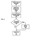
- FIG. 2 is a flow chart of a method of adaptive AFC combining as described above.
- the method begins in general with a step of collecting a plurality of uncompensated channel parameters, e.g., channel estimates, each of which is based on a respective de-spread correlated signal (step 202).
- the uncompensated channel estimates are used in the above-described AFC-like computations to determine respective residual frequency offsets for the correlated signals (step 204).
- the residual frequency offsets or a function ⁇ f err , f res of the offsets are then compared to a threshold (step 206).
- a sub-set of the fingers e.g., one of the fingers or the fingers corresponding to one cell, is selected (step 210) and only the uncompensated channel estimates for the selected finger(s) are used in the above-described typical AFC computations to determine the control signal f err (step 212).
- the selected finger, or cell may be the strongest one received or the HSDPA serving cell.
- the threshold is not exceeded (No in step 208)
- another setting is used. For example, an average of the uncompensated channel estimates of several or all of the fingers/cells are used in the typical AFC computations to determine the control signal f err (step 212). Suitable threshold values can be readily determined based on experiment and design preference and depend on, for example, the function ⁇ f err , f res used.
- FIG. 3 is a block diagram of an apparatus 300, which may be a portion of a receiver in a typical UE or BS, that can carry out adaptive AFC combining as described above. Those components of the apparatus 300 that are the same or substantially the same as the components of the apparatus 100 have the same reference numerals.
- the apparatus 300 includes a controllable oscillator 102 that generates the LO signal used by an RX Fe 104.
- the frequency of the LO signal produced by the oscillator 102 is responsive to a control signal f err generated by an AFC 106, and as illustrated, the control signal produced by the AFC 106 may be converted to an analog control signal by a DAC 107.
- the AFC 106 generates the control signal f err according to the typical AFC computations, but in the apparatus 300, the control signal f err is based on selected uncompensated channel estimates ⁇ f from a channel estimator 108, which computes the estimates based on de-spread correlated signals from the de-spreader 114.
- the channel estimator 108 provides the uncompensated channel estimates to a residual frequency offset and threshold device 302, which computes the residual frequency offset per finger f err , f res according to the AFC-like computations described above. If the value of a function of the residual frequency offsets exceeds a suitable threshold, the device 302 causes the AFC 106, for example in response to a control signal, to generate the control signal f err based on uncompensated channel estimates of, for example, only one finger. It is currently believed that, in some situations, it may be useful to use the finger that is not necessarily the largest, e.g., the HSDPA serving cell when applicable. It will be understood that the device 302 is shown in FIG. 3 as a separate block, but this is not necessary. The computations performed by the device 302 can be performed by any other suitable processor or logic device in the receiver, such as the AFC 106.
- Adaptive AFC combining provides an alternative way to cope with the negative effects of large residual frequency offsets.
- the AFC may report the frequency error of one finger instead of an average value, which ensures that at least that finger is usable for SIR estimation, CPICH-DPCH gain estimation, combining, etc. It is currently believed that adaptive AFC combining is probably not needed when compensation of residual frequency offset is employed as described in more detail below.
- ⁇ f err , f res can be seen as a form of velocity estimate because large residual frequency offset values occur only in high-velocity situations (or if the AFC and/or LO is not working properly, or if the LOs are not well aligned in frequency). Even so, it should be understood that a high value of ⁇ f err , f res may not be seen in all high-velocity situations, e.g., a single-cell, LOS situation.
- ⁇ f err , f res can advantageously be used as a supplementary velocity estimate, which can be combined in a logical-OR fashion with, for example, a conventional Doppler estimate or other velocity estimate, and possibly with methods described in U.S. Patent Application US 2008014881, filed on July 12, 2006, by K. Engdahl et al. , for "Detection of High Velocity Movement in a Telecommunication System”; and U.S. Patent Application US 2008013649, filed on July 12, 2006, by K. Engdahl , for "AFC Wrap-Around Detection".
- a receiver may switch into a high-speed mode of operation when at least one of these velocity estimates indicates high speed, and use a low-speed mode of operation only when all of these velocity estimates indicate low speed.
- the Doppler-spread estimator 116 in the apparatus 300 may apply an argument- (or zero- ) crossing algorithm or a level-crossing algorithm, for example, to received signals.
- At least the AFC 106 combines the estimates of the Doppler spread from the estimator 116 with a control signal, which the AFC 106 can either compute itself or receive from the device 302, in a logical OR fashion.
- the control signal indicates high velocity if the value of ⁇ f err , f res exceeds a threshold, and low velocity otherwise. This will be seen to be the result of a method that includes steps 202-208 in FIG. 2 .
- the AFC can set its operating mode as either low-speed mode or a higher-speed mode.
- the control signal f err may be based on one channel estimate per finger in low-speed mode, and on five channel estimates per finger in high-speed mode.
- One can also look at just one finger, e.g., ⁇ f err , f res f err , 1 res , which is currently believed likely to work well when the above-described adaptive AFC combining is used but not so well in other situations.
- the improved velocity estimation has many applications in current communication system receivers.
- the improved velocity estimation provides a more reliable speed-mode setting, reducing the risk of remaining in low-speed mode when the velocity is actually high, which can be detrimental to receiver performance.
- the residual frequency offsets can be used for compensating received correlated signals.
- the inventor has recognized that it is desirable to perform such compensation only when it is necessary, e.g., when there is a large residual frequency offset.
- residual frequency offset compensation is advantageously selectively enabled only when ⁇ f err , f res exceeds a selected threshold (which may be different from the threshold used for adaptive AFC combining and/or the threshold used for improved velocity estimation). Adaptive residual frequency offset compensation is thus switched off in situations where a large residual frequency offset is not experienced, which thereby reduces the computational effort of the receiver.
- Compensating for residual frequency offsets comprises frequency-error correction, i.e., de-rotation, of de-spread symbols for each finger or transmitter.
- the transmitter may be a BS or cell in a cellular mobile telephone system, and that compensation per finger is equivalent to compensation per transmitter in many useful communication situations.
- the transmitter may be a UE that a BS is receiving.
- this invention can be used in peer-to-peer communication systems and in other systems, such as broadcasting systems (e.g., mobile television and the like).
- a receiver that implements equations (1) and (2) also needs channel estimates derived from uncompensated symbols.
- channel estimates must be produced both based on compensated and on uncompensated symbols.
- the compensation might be undone by re-rotating the channel estimates derived from compensated symbols in order to obtain channel estimates based on uncompensated symbols.
- Such "uncompensated" channel estimates would be used in an AFC in the receiver.
- compensation according to equations (1) and (2) may be switched on only when there is at least one large residual frequency offset f err , f res .
- Such selective enablement can be implemented by comparing max f f err , f res or another suitable function of f err , f res to a threshold value, and generating compensated symbols when the threshold is crossed and not generating compensated symbols otherwise.
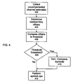
- FIG. 4 is a flow chart of a method of adaptive residual frequency offset compensation as described above.
- the method begins in general with a step of collecting a plurality of uncompensated channel estimates, each of which is based on a respective de-spread uncompensated correlated signal (step 402).
- the uncompensated channel estimates are used in the above-described AFC-like computations to determine respective residual frequency offsets for the correlated signals (step 404).
- the residual frequency offsets or a function of them are then compared to a threshold (step 406). If the threshold is exceeded (Yes in step 408), symbols compensated for the residual frequency offsets are generated (step 410).
- the compensated symbols can be used for symbol operations (step 412), such as channel estimation, SIR and power estimation, etc.
- the uncompensated symbols are used for the symbol operations (step 412).
- Suitable threshold values can be readily determined based on experiment and design preference and depend on, for example, the function ⁇ f err , f res used.
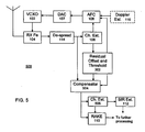
- FIG. 5 is a block diagram of an apparatus 500, which may be a portion of a receiver in a typical UE or BS, that can carry out adaptive residual frequency offset compensation as described above.
- Those components of the apparatus 500 that are the same or substantially the same as the components of the apparatuses 100, 300 have the same reference numerals.
- uncompensated channel estimates are provided by the channel estimator 108 to the residual frequency offset and threshold device 302, which computes the residual frequency offset per finger f err , f res according to the AFC-like computations described above. It will be understood that the device 302 is shown in FIG. 5 as a separate block, but this is not necessary. The computations performed by the device 302 can be performed by any other suitable processor or logic device in the receiver, such as the AFC 106.
- the respective residual frequency offsets for the fingers generated by the device 302 are provided to a compensator 504 together with the uncompensated de-spread correlated signals generated by the de-spreader 114.
- the compensator 504 generates compensated de-spread symbols (correlated signals) according to equations (1) and (2).
- the operation of the compensator 504 can be selectively enabled/disabled based on the residual frequency offsets, Le., by thresholding ⁇ f err , f res , and such thresholding can be carried out by a suitably programmed or configured device 302.
- compensated de-spread symbols are provided to a channel estimator 506 and the RAKE combiner 110, which use the compensated de-spread symbols in the usual ways.
- channel estimates based on compensated de-spread symbols are provided to the RAKE combiner 110 and the SIR estimator 112.
- the compensator 504 is not enabled, the uncompensated channel estimates generated by the estimator 108 may be fed through to the RAKE combiner 110, which also receives the de-spread signals generated by the de-spreader 114, and to the SIR estimator 112.
- FIG. 5 indicates two separate channel estimators 108, 506, this is not necessary.
- a single set of hardware or a single processor suitably configured or programmed can be used to perform the necessary operations.
- an attractive alternative to the arrangement depicted in FIG. 5 may be to compensate only de-spread pilot symbols rather than de-spread pilot and other (e.g., traffic or data) symbols. In this way, fewer (symbol) compensations would be performed as the estimator 506 needs only the (compensated) pilot symbols to determine the (compensated) channel estimates.
- additional compensation may be carried out by the RAKE combiner 110 or another suitable device.
- this invention can additionally be considered to be embodied entirely within any form of computer-readable storage medium having stored therein an appropriate set of instructions for use by or in connection with an instruction-execution system, apparatus, or device, such as a computer-based system, processor-containing system, or other system that can fetch instructions from a medium and execute the instructions.
- a "computer-readable medium” can be any means that can contain, store, communicate, propagate, or transport the program for use by or in connection with the instruction-execution system, apparatus, or device.
- the computer-readable medium can be, for example but not limited to, an electronic, magnetic, optical, electromagnetic, infrared, or semiconductor system, apparatus, device, or propagation medium.
- the computer-readable medium include an electrical connection having one or more wires, a portable computer diskette, a random-access memory (RAM), a read-only memory (ROM), an erasable programmable read-only memory (EPROM or Flash memory), and an optical fiber.
- RAM random-access memory
- ROM read-only memory
- EPROM or Flash memory erasable programmable read-only memory
Landscapes
- Engineering & Computer Science (AREA)
- Computer Networks & Wireless Communication (AREA)
- Signal Processing (AREA)
- Circuits Of Receivers In General (AREA)
- Emergency Alarm Devices (AREA)
- Rear-View Mirror Devices That Are Mounted On The Exterior Of The Vehicle (AREA)
- Transmitters (AREA)
- Mobile Radio Communication Systems (AREA)
Claims (14)
- Verfahren zum Steuern eines RAKE-Empfängers auf der Basis eines Signals, das durch einen Kommunikationskanal empfangen wird, umfassend die folgenden Schritte:Sammeln (202) einer Mehrzahl von Schätzungen einer Impulsantwort des Kommunikationskanals;Bestimmen (204) einer Mehrzahl von Restfrequenzversätzen aus der Mehrzahl von Schätzungen der Impulsantwort des Kommunikationskanals; undBestimmen eines Betriebsmodus des Empfängers auf der Basis eines Vergleichs (208) eines Wertes einer Funktion ζ wenigstens eines der Mehrzahl von Restfrequenzversätzen mit einem Schwellenwert, wobei die Funktion ζ wenigstens eines der Mehrzahl von Restfrequenzversätzen eine von


- Verfahren nach Anspruch 1, wobei der Schritt des Bestimmens des Betriebsmodus umfasst: Auswählen einer ersten Gruppe von Schätzungen der Impulsantwort des Kommunikationskanals für automatische Frequenzregelungs- oder AFC-Berechnungen unter Verwendung der ersten Gruppe, wenn der Vergleich anzeigt, dass der Wert der Funktion ζ den Schwellenwert überschreitet; und Auswählen einer zweiten Gruppe von Schätzungen der Impulsantwort des Kommunikationskanals für AFC-Berechnungen unter Verwendung der zweiten Gruppe, wenn der Wert des Vergleichs anzeigt, dass der Wert der Funktion ζ den Schwellenwert nicht überschritt; wobei die erste Gruppe nicht dieselbe wie die zweite Gruppe ist.
- Verfahren nach Anspruch 1, ferner umfassend den Schritt des Erzeugens einer Geschwindigkeitsschätzung, wobei die Geschwindigkeitsschätzung auf der Funktion ζ der Mehrzahl von Restfrequenzversätzen basiert.
- Verfahren nach Anspruch 1, wobei der Schritt des Bestimmens des Betriebsmodus ein Erzeugen von restfrequenzversatzkompensierten Symbolen umfasst, wenn der Vergleich anzeigt, dass der Wert der Funktion ζ den Schwellenwert überschreitet.
- Verfahren nach Anspruch 4, wobei die restfrequenzversatzkompensierten Symbole für Symboloperationen verwendet werden.
- Verfahren nach Anspruch 5, wobei, wenn der Vergleich anzeigt, dass der Wert der Funktion ζ den Schwellenwert nicht überschritt, unkompensierte Symbole für die Symboloperationen verwendet werden.
- Vorrichtung zum Steuern eines RAKE-Empfängers auf der Basis eines Signals, das durch einen Kommunikationskanal empfangen wird, umfassend:einen Entspreizer (114), der so konfiguriert ist, dass er korrelierte Signale aus einem Signal erzeugt, das durch den Kommunikationssignal empfangen wird;eine Kanalschätzfunktion (108), die so konfiguriert ist, dass sie eine Mehrzahl von Schätzungen einer Impulsantwort des Kommunikationskanals aus korrelierten Signalen erzeugt;einen Restfrequenzversatzrechner (302), der so konfiguriert ist, dass er einen Satz von Restfrequenzversätzen auf der Basis der Mehrzahl von Schätzungen der Impulsantwort des Kommunikationskanals bestimmt; undeine Steuerung, die so konfiguriert ist, dass sie einen Betriebsmodus des Empfängers auf der Basis eines Vergleichs eines Wertes einer Funktion ζ wenigstens eines der Mehrzahl von Restfrequenzversätzen mit einem Schwellenwert bestimmt, wobei die Funktion ζ der Mehrzahl von Restfrequenzversätzen eine von


- Vorrichtung nach Anspruch 7, wobei die Steuerung so konfiguriert ist, dass sie ein Steuersignal ferr auf der Basis von ausgewählten Schätzungen der Impulsantwort des Kommunikationskanals erzeugt, und ein Betriebsmodus der Steuerung auf der Basis wenigstens eines des Satzes von Restfrequenzversätzen bestimmt wird.
- Vorrichtung nach Anspruch 8, wobei die Steuerung das Steuersignal ferr auf der Basis der ersten Gruppe von Schätzungen der Impulsantwort des Kommunikationskanals erzeugt, wenn die Schwelle überschritten wird; die Steuerung das Steuersignal ferr auf der Basis einer zweiten Gruppe von Schätzungen der Impulsantwort des Kommunikationskanals erzeugt, wenn die Schwelle nicht überschritten wird; und die erste Gruppe nicht dieselbe wie die zweite Gruppe ist.
- Vorrichtung nach Anspruch 8, wobei der Restfrequenzversatzrechner so konfiguriert ist, dass er eine Geschwindigkeitsschätzung erzeugt, die auf der Funktion ζ der Mehrzahl von Restfrequenzversätzen basiert.
- Vorrichtung nach Anspruch 7, ferner umfassend einen Kompensator, der so konfiguriert ist, dass er kompensierte entspreizte Symbole aus den korrelierten Signalen und den Restfrequenzversätzen erzeugt, wobei der Kompensator basierend auf dem Vergleich des Wertes der Funktion ζ mit dem Schwellenwert selektiv aktiviert wird.
- Vorrichtung nach Anspruch 11, wobei der Kompensator aktiviert wird, wenn der Vergleich anzeigt, dass der Wert der Funktion ζ den Schwellenwert überschreitet.
- Vorrichtung nach Anspruch 12, wobei die restfrequenzversatzkompensierten Symbole für Symboloperationen verwendet werden.
- Vorrichtung nach Anspruch 13, wobei, wenn der Vergleich anzeigt, dass der Wert der Funktion ζ den Schwellenwert nicht überschritt, unkompensierte Symbole für die Symboloperationen verwendet werden.
Applications Claiming Priority (2)
| Application Number | Priority Date | Filing Date | Title |
|---|---|---|---|
| US11/457,029 US8184675B2 (en) | 2006-07-12 | 2006-07-12 | Residual frequency offset exploitation |
| PCT/EP2007/055899 WO2008006662A1 (en) | 2006-07-12 | 2007-06-14 | Residual frequency offset exploitation |
Publications (2)
| Publication Number | Publication Date |
|---|---|
| EP2039017A1 EP2039017A1 (de) | 2009-03-25 |
| EP2039017B1 true EP2039017B1 (de) | 2009-11-18 |
Family
ID=37671085
Family Applications (1)
| Application Number | Title | Priority Date | Filing Date |
|---|---|---|---|
| EP07765420A Not-in-force EP2039017B1 (de) | 2006-07-12 | 2007-06-14 | Ausnutzung des restfrequenzoffsets |
Country Status (5)
| Country | Link |
|---|---|
| US (1) | US8184675B2 (de) |
| EP (1) | EP2039017B1 (de) |
| AT (1) | ATE449467T1 (de) |
| DE (1) | DE602007003367D1 (de) |
| WO (1) | WO2008006662A1 (de) |
Families Citing this family (14)
| Publication number | Priority date | Publication date | Assignee | Title |
|---|---|---|---|---|
| US20060209932A1 (en) * | 2005-03-18 | 2006-09-21 | Qualcomm Incorporated | Channel estimation for single-carrier systems |
| US7873125B2 (en) * | 2006-11-30 | 2011-01-18 | Broadcom Corporation | Method and system for sliding window phase estimator for WCDMA automatic frequency correction |
| US7809043B2 (en) * | 2006-11-30 | 2010-10-05 | Broadcom Corporation | Method and system for a flexible automatic frequency control (AFC) design supporting transmit diversity |
| ATE519309T1 (de) | 2008-11-03 | 2011-08-15 | Ericsson Telefon Ab L M | Schätzung einer frequenzumsetzung |
| EP2371099B1 (de) * | 2008-12-23 | 2013-05-29 | Telefonaktiebolaget L M Ericsson (publ) | Verfahren und Vorrichtung zur Empfängerfrequenzfehlerkompensation |
| WO2010122444A1 (en) * | 2009-04-23 | 2010-10-28 | Koninklijke Philips Electronics N.V. | Frequency offset and channel gain tracking for enhanced transmission efficiency |
| US8447005B2 (en) | 2009-11-05 | 2013-05-21 | Telefonaktiebolaget L M Ericsson (Publ) | Frequency synchronization methods and apparatus |
| EP2663044B1 (de) * | 2012-02-13 | 2016-04-27 | Huawei Technologies Co., Ltd. | Verfahren, vorrichtung und system zur messung eines kanalfrequenzversatzes |
| TWI462539B (zh) * | 2012-03-06 | 2014-11-21 | Mstar Semiconductor Inc | 頻率校正方法 |
| CN102694570B (zh) * | 2012-05-22 | 2014-05-28 | 杭州电子科技大学 | 一种大频偏条件下扩频通信系统自动频率控制方法 |
| US10554355B2 (en) | 2016-09-30 | 2020-02-04 | Apple Inc. | Station (STA) and method for usage of phase noise compensation based on operational parameters |
| CN106254285A (zh) * | 2016-09-30 | 2016-12-21 | 金陵科技学院 | 自组网宽带无线通信基带处理方法 |
| WO2019158182A1 (en) * | 2018-02-13 | 2019-08-22 | Abb Schweiz Ag | Frequency estimation in a wireless communication network for power grid control |
| CN112929311B (zh) * | 2021-01-26 | 2023-01-03 | 白盒子(上海)微电子科技有限公司 | 一种控制信道多用户复用时高精度频偏估计方法 |
Family Cites Families (27)
| Publication number | Priority date | Publication date | Assignee | Title |
|---|---|---|---|---|
| US5361276A (en) * | 1993-09-13 | 1994-11-01 | At&T Bell Laboratories | All digital maximum likelihood based spread spectrum receiver |
| US5878093A (en) * | 1996-12-16 | 1999-03-02 | Ericsson Inc. | Interference rejection combining with frequency correction |
| US6522696B1 (en) * | 1997-04-11 | 2003-02-18 | Agere Systems Inc. | Adaptive frequency correction in a wireless communications system, such as for GSM and IS54 |
| US6560273B1 (en) | 1998-10-07 | 2003-05-06 | Ericsson Inc. | Delay searcher and delay trackers interaction for new delays assignment to rake fingers |
| US6278725B1 (en) | 1998-12-18 | 2001-08-21 | Philips Electronics North America Corporation | Automatic frequency control loop multipath combiner for a rake receiver |
| US6922434B2 (en) * | 1999-10-19 | 2005-07-26 | Ericsson Inc. | Apparatus and methods for finger delay selection in RAKE receivers |
| US6608858B1 (en) | 2000-01-26 | 2003-08-19 | Qualcomm Incorporated | Multipath doppler adjusted frequency tracking loop |
| JP3497480B2 (ja) | 2000-09-04 | 2004-02-16 | 松下電器産業株式会社 | 位相回転検出装置及びそれを備えた無線基地局装置 |
| US7443826B1 (en) | 2000-10-04 | 2008-10-28 | Telefonaktiebolaget L M Ericsson (Publ) | Method and apparatus for automatic frequency control in a CDMA receiver |
| FR2816776B1 (fr) * | 2000-11-10 | 2003-02-07 | Cit Alcatel | Procede de correction de l'erreur de frequence |
| US20040066737A1 (en) | 2001-05-30 | 2004-04-08 | Takuya Sakaishi | Automatic frequency control device and automatic frequency control method |
| US7088955B2 (en) | 2001-07-16 | 2006-08-08 | Qualcomm Inc. | Method and apparatus for acquiring and tracking pilots in a CDMA communication system |
| US6741665B2 (en) * | 2002-06-20 | 2004-05-25 | Nokia Corporation | Method and apparatus providing an amplitude independent automatic frequency control circuit |
| US6760573B2 (en) * | 2002-07-09 | 2004-07-06 | Qualcomm Incorporated | Frequency tracking using inner and outer loops |
| EP1383239A1 (de) | 2002-07-17 | 2004-01-21 | STMicroelectronics N.V. | Verfahren und Einrichtung zur automatischen Frequenzregelung in einem DS-CDMA-Empfänger |
| KR100840608B1 (ko) * | 2002-07-27 | 2008-06-23 | 삼성전자주식회사 | 인터리브된 주파수 분할 다중 접속을 위한 주파수 오프셋보상 방법 및 장치 |
| KR100557112B1 (ko) | 2002-09-11 | 2006-03-03 | 삼성전자주식회사 | 이동통신시스템의 수신단에서의 주파수 오차를 추정하여 결합하는 장치 |
| JP3877158B2 (ja) | 2002-10-31 | 2007-02-07 | ソニー・エリクソン・モバイルコミュニケーションズ株式会社 | 周波数偏移検出回路及び周波数偏移検出方法、携帯通信端末 |
| DE10251313B4 (de) * | 2002-11-04 | 2007-05-03 | Advanced Micro Devices, Inc., Sunnyvale | Gemeinsame Benutzung eines Schaltkreises für Frequenz- und Phasenfehlerkorrektur |
| US6980775B2 (en) * | 2002-12-30 | 2005-12-27 | Motorola, Inc. | Automatic frequency control (AFC) system and method using an adaptive threshold to improve accuracy of the direct current (DC) component calculation for a received signal |
| CN1647430A (zh) | 2003-02-25 | 2005-07-27 | 连宇通信有限公司 | 一种载波频率估计方法及装置 |
| KR100630043B1 (ko) | 2003-11-06 | 2006-09-27 | 삼성전자주식회사 | 이동통신시스템의 수신단에서의 주파수 오차 추정 및 결합기 |
| US7433433B2 (en) | 2003-11-13 | 2008-10-07 | Telefonaktiebolaget L M Ericsson (Publ) | Channel estimation by adaptive interpolation |
| JP4190406B2 (ja) | 2003-12-25 | 2008-12-03 | 三洋電機株式会社 | 周波数オフセット推定方法およびそれを利用した周波数オフセット補正装置 |
| US8107512B2 (en) | 2004-03-08 | 2012-01-31 | Thomson Licensing | Method and apparatus for robust automatic frequency control in CDMA systems with constant pilot signals |
| US7555074B2 (en) * | 2005-02-01 | 2009-06-30 | Telefonaktiebolaget L M Ericsson (Publ) | Interference estimation in the presence of frequency errors |
| CN1317830C (zh) * | 2005-04-15 | 2007-05-23 | 展讯通信(上海)有限公司 | 自动频偏校正方法及使用该方法的装置和接收机 |
-
2006
- 2006-07-12 US US11/457,029 patent/US8184675B2/en not_active Expired - Fee Related
-
2007
- 2007-06-14 WO PCT/EP2007/055899 patent/WO2008006662A1/en not_active Ceased
- 2007-06-14 EP EP07765420A patent/EP2039017B1/de not_active Not-in-force
- 2007-06-14 AT AT07765420T patent/ATE449467T1/de not_active IP Right Cessation
- 2007-06-14 DE DE602007003367T patent/DE602007003367D1/de not_active Expired - Fee Related
Also Published As
| Publication number | Publication date |
|---|---|
| WO2008006662A1 (en) | 2008-01-17 |
| DE602007003367D1 (de) | 2009-12-31 |
| US20080013650A1 (en) | 2008-01-17 |
| ATE449467T1 (de) | 2009-12-15 |
| US8184675B2 (en) | 2012-05-22 |
| EP2039017A1 (de) | 2009-03-25 |
Similar Documents
| Publication | Publication Date | Title |
|---|---|---|
| EP2039017A1 (de) | Ausnutzung des restfrequenzoffsets | |
| US7349379B2 (en) | Channel normalization | |
| EP1496628B1 (de) | Mobilkommunikationssystem, mobilstation, basisstation, kommunikationsweg-qualitätsschätzverfahren dafür | |
| EP1028556B1 (de) | Zeit- und Raumdiversität für WCDMA | |
| CN101523748B (zh) | 对G-Rake接收机的多普勒频率控制 | |
| US20040203812A1 (en) | Communication receiver with an adaptive equalizer that uses channel estimation | |
| US20080064408A1 (en) | Derivation of optimal antenna weights during soft handover | |
| US7876808B2 (en) | Method and apparatus for adaptive noise and/or signal filtering in an HSDPA channel quality indicator (CQI) selection | |
| US20060073790A1 (en) | Method and system for weight determination in a spatial multiplexing MIMO system for WCDMA/HSDPA | |
| US7085317B2 (en) | Communication receiver with an adaptive equalizer length | |
| US7796680B2 (en) | Mobile communication system and wireless apparatus to be used for the same | |
| KR20040017856A (ko) | 무선 통신 시스템용 적응형 파일럿 필터의 선택 | |
| CN1708966B (zh) | 在发射波束成形存在时用于信道估计的方法 | |
| EP1845634B1 (de) | Verfahren und System für geregelte Diversitätsverarbeitung mittels dediziertem Pilotkanal | |
| WO2009132937A1 (en) | A method and apparatus for compensating for processing timing misalignment in a communication receiver | |
| US20040038702A1 (en) | Radio communication method, base station and mobile station | |
| US8526556B2 (en) | Method and system for delay locked loop for rake receiver | |
| EP1298814B1 (de) | CDMA-Empfänger und Kanalschätzungsverfahren | |
| KR100578435B1 (ko) | 확산 스팩트럼 통신 시스템에서 포워드 전력 제어를 위한Eb/Nt 추정용 방법과 장치 | |
| EP1753153A2 (de) | Vorrichtung zur Diversitätsübertragung und Steuerverfahren dafür in einem mobilen Übertragungssystem | |
| US20070058708A1 (en) | Method and apparatus for automatically correcting receiver oscillator frequency | |
| US20060074612A1 (en) | Method and system for weight determination in a single channel (SC) multiple-input multiple-output (MIMO) system for WCDMA/HSDPA | |
| KR20050043470A (ko) | 이동통신시스템의 수신단에서의 주파수 오차 추정 및 결합기 | |
| EP1794897B1 (de) | Ableitung der optimalen antennengewichtung während eines sanften weiterreichens | |
| US8295840B2 (en) | Mobile station and feedback information generating method |
Legal Events
| Date | Code | Title | Description |
|---|---|---|---|
| PUAI | Public reference made under article 153(3) epc to a published international application that has entered the european phase |
Free format text: ORIGINAL CODE: 0009012 |
|
| 17P | Request for examination filed |
Effective date: 20090109 |
|
| AK | Designated contracting states |
Kind code of ref document: A1 Designated state(s): AT BE BG CH CY CZ DE DK EE ES FI FR GB GR HU IE IS IT LI LT LU LV MC MT NL PL PT RO SE SI SK TR |
|
| AX | Request for extension of the european patent |
Extension state: AL BA HR MK RS |
|
| GRAP | Despatch of communication of intention to grant a patent |
Free format text: ORIGINAL CODE: EPIDOSNIGR1 |
|
| GRAS | Grant fee paid |
Free format text: ORIGINAL CODE: EPIDOSNIGR3 |
|
| GRAA | (expected) grant |
Free format text: ORIGINAL CODE: 0009210 |
|
| AK | Designated contracting states |
Kind code of ref document: B1 Designated state(s): AT BE BG CH CY CZ DE DK EE ES FI FR GB GR HU IE IS IT LI LT LU LV MC MT NL PL PT RO SE SI SK TR |
|
| REG | Reference to a national code |
Ref country code: GB Ref legal event code: FG4D |
|
| REG | Reference to a national code |
Ref country code: CH Ref legal event code: EP |
|
| REG | Reference to a national code |
Ref country code: IE Ref legal event code: FG4D |
|
| REF | Corresponds to: |
Ref document number: 602007003367 Country of ref document: DE Date of ref document: 20091231 Kind code of ref document: P |
|
| REG | Reference to a national code |
Ref country code: NL Ref legal event code: VDEP Effective date: 20091118 |
|
| LTIE | Lt: invalidation of european patent or patent extension |
Effective date: 20091118 |
|
| PG25 | Lapsed in a contracting state [announced via postgrant information from national office to epo] |
Ref country code: SE Free format text: LAPSE BECAUSE OF FAILURE TO SUBMIT A TRANSLATION OF THE DESCRIPTION OR TO PAY THE FEE WITHIN THE PRESCRIBED TIME-LIMIT Effective date: 20091118 Ref country code: LT Free format text: LAPSE BECAUSE OF FAILURE TO SUBMIT A TRANSLATION OF THE DESCRIPTION OR TO PAY THE FEE WITHIN THE PRESCRIBED TIME-LIMIT Effective date: 20091118 Ref country code: IS Free format text: LAPSE BECAUSE OF FAILURE TO SUBMIT A TRANSLATION OF THE DESCRIPTION OR TO PAY THE FEE WITHIN THE PRESCRIBED TIME-LIMIT Effective date: 20100318 Ref country code: ES Free format text: LAPSE BECAUSE OF FAILURE TO SUBMIT A TRANSLATION OF THE DESCRIPTION OR TO PAY THE FEE WITHIN THE PRESCRIBED TIME-LIMIT Effective date: 20100228 Ref country code: FI Free format text: LAPSE BECAUSE OF FAILURE TO SUBMIT A TRANSLATION OF THE DESCRIPTION OR TO PAY THE FEE WITHIN THE PRESCRIBED TIME-LIMIT Effective date: 20091118 Ref country code: PT Free format text: LAPSE BECAUSE OF FAILURE TO SUBMIT A TRANSLATION OF THE DESCRIPTION OR TO PAY THE FEE WITHIN THE PRESCRIBED TIME-LIMIT Effective date: 20100318 |
|
| PG25 | Lapsed in a contracting state [announced via postgrant information from national office to epo] |
Ref country code: SI Free format text: LAPSE BECAUSE OF FAILURE TO SUBMIT A TRANSLATION OF THE DESCRIPTION OR TO PAY THE FEE WITHIN THE PRESCRIBED TIME-LIMIT Effective date: 20091118 Ref country code: CY Free format text: LAPSE BECAUSE OF FAILURE TO SUBMIT A TRANSLATION OF THE DESCRIPTION OR TO PAY THE FEE WITHIN THE PRESCRIBED TIME-LIMIT Effective date: 20091118 Ref country code: PL Free format text: LAPSE BECAUSE OF FAILURE TO SUBMIT A TRANSLATION OF THE DESCRIPTION OR TO PAY THE FEE WITHIN THE PRESCRIBED TIME-LIMIT Effective date: 20091118 Ref country code: LV Free format text: LAPSE BECAUSE OF FAILURE TO SUBMIT A TRANSLATION OF THE DESCRIPTION OR TO PAY THE FEE WITHIN THE PRESCRIBED TIME-LIMIT Effective date: 20091118 |
|
| PG25 | Lapsed in a contracting state [announced via postgrant information from national office to epo] |
Ref country code: AT Free format text: LAPSE BECAUSE OF FAILURE TO SUBMIT A TRANSLATION OF THE DESCRIPTION OR TO PAY THE FEE WITHIN THE PRESCRIBED TIME-LIMIT Effective date: 20091118 Ref country code: BE Free format text: LAPSE BECAUSE OF FAILURE TO SUBMIT A TRANSLATION OF THE DESCRIPTION OR TO PAY THE FEE WITHIN THE PRESCRIBED TIME-LIMIT Effective date: 20091118 |
|
| PG25 | Lapsed in a contracting state [announced via postgrant information from national office to epo] |
Ref country code: EE Free format text: LAPSE BECAUSE OF FAILURE TO SUBMIT A TRANSLATION OF THE DESCRIPTION OR TO PAY THE FEE WITHIN THE PRESCRIBED TIME-LIMIT Effective date: 20091118 Ref country code: RO Free format text: LAPSE BECAUSE OF FAILURE TO SUBMIT A TRANSLATION OF THE DESCRIPTION OR TO PAY THE FEE WITHIN THE PRESCRIBED TIME-LIMIT Effective date: 20091118 Ref country code: NL Free format text: LAPSE BECAUSE OF FAILURE TO SUBMIT A TRANSLATION OF THE DESCRIPTION OR TO PAY THE FEE WITHIN THE PRESCRIBED TIME-LIMIT Effective date: 20091118 Ref country code: BG Free format text: LAPSE BECAUSE OF FAILURE TO SUBMIT A TRANSLATION OF THE DESCRIPTION OR TO PAY THE FEE WITHIN THE PRESCRIBED TIME-LIMIT Effective date: 20100218 Ref country code: DK Free format text: LAPSE BECAUSE OF FAILURE TO SUBMIT A TRANSLATION OF THE DESCRIPTION OR TO PAY THE FEE WITHIN THE PRESCRIBED TIME-LIMIT Effective date: 20091118 |
|
| PG25 | Lapsed in a contracting state [announced via postgrant information from national office to epo] |
Ref country code: SK Free format text: LAPSE BECAUSE OF FAILURE TO SUBMIT A TRANSLATION OF THE DESCRIPTION OR TO PAY THE FEE WITHIN THE PRESCRIBED TIME-LIMIT Effective date: 20091118 Ref country code: CZ Free format text: LAPSE BECAUSE OF FAILURE TO SUBMIT A TRANSLATION OF THE DESCRIPTION OR TO PAY THE FEE WITHIN THE PRESCRIBED TIME-LIMIT Effective date: 20091118 |
|
| PLBE | No opposition filed within time limit |
Free format text: ORIGINAL CODE: 0009261 |
|
| STAA | Information on the status of an ep patent application or granted ep patent |
Free format text: STATUS: NO OPPOSITION FILED WITHIN TIME LIMIT |
|
| 26N | No opposition filed |
Effective date: 20100819 |
|
| PG25 | Lapsed in a contracting state [announced via postgrant information from national office to epo] |
Ref country code: GR Free format text: LAPSE BECAUSE OF FAILURE TO SUBMIT A TRANSLATION OF THE DESCRIPTION OR TO PAY THE FEE WITHIN THE PRESCRIBED TIME-LIMIT Effective date: 20100219 |
|
| PG25 | Lapsed in a contracting state [announced via postgrant information from national office to epo] |
Ref country code: MC Free format text: LAPSE BECAUSE OF NON-PAYMENT OF DUE FEES Effective date: 20100630 |
|
| REG | Reference to a national code |
Ref country code: FR Ref legal event code: ST Effective date: 20110228 |
|
| PG25 | Lapsed in a contracting state [announced via postgrant information from national office to epo] |
Ref country code: IT Free format text: LAPSE BECAUSE OF FAILURE TO SUBMIT A TRANSLATION OF THE DESCRIPTION OR TO PAY THE FEE WITHIN THE PRESCRIBED TIME-LIMIT Effective date: 20091118 |
|
| PG25 | Lapsed in a contracting state [announced via postgrant information from national office to epo] |
Ref country code: DE Free format text: LAPSE BECAUSE OF NON-PAYMENT OF DUE FEES Effective date: 20110101 Ref country code: IE Free format text: LAPSE BECAUSE OF NON-PAYMENT OF DUE FEES Effective date: 20100614 Ref country code: MT Free format text: LAPSE BECAUSE OF FAILURE TO SUBMIT A TRANSLATION OF THE DESCRIPTION OR TO PAY THE FEE WITHIN THE PRESCRIBED TIME-LIMIT Effective date: 20091118 |
|
| PG25 | Lapsed in a contracting state [announced via postgrant information from national office to epo] |
Ref country code: FR Free format text: LAPSE BECAUSE OF NON-PAYMENT OF DUE FEES Effective date: 20100630 |
|
| REG | Reference to a national code |
Ref country code: CH Ref legal event code: PL |
|
| PG25 | Lapsed in a contracting state [announced via postgrant information from national office to epo] |
Ref country code: LI Free format text: LAPSE BECAUSE OF NON-PAYMENT OF DUE FEES Effective date: 20110630 Ref country code: CH Free format text: LAPSE BECAUSE OF NON-PAYMENT OF DUE FEES Effective date: 20110630 |
|
| PG25 | Lapsed in a contracting state [announced via postgrant information from national office to epo] |
Ref country code: HU Free format text: LAPSE BECAUSE OF FAILURE TO SUBMIT A TRANSLATION OF THE DESCRIPTION OR TO PAY THE FEE WITHIN THE PRESCRIBED TIME-LIMIT Effective date: 20100519 Ref country code: LU Free format text: LAPSE BECAUSE OF NON-PAYMENT OF DUE FEES Effective date: 20100614 |
|
| PG25 | Lapsed in a contracting state [announced via postgrant information from national office to epo] |
Ref country code: TR Free format text: LAPSE BECAUSE OF FAILURE TO SUBMIT A TRANSLATION OF THE DESCRIPTION OR TO PAY THE FEE WITHIN THE PRESCRIBED TIME-LIMIT Effective date: 20091118 |
|
| REG | Reference to a national code |
Ref country code: GB Ref legal event code: 732E Free format text: REGISTERED BETWEEN 20131205 AND 20131211 |
|
| REG | Reference to a national code |
Ref country code: GB Ref legal event code: 732E Free format text: REGISTERED BETWEEN 20131212 AND 20131218 |
|
| REG | Reference to a national code |
Ref country code: GB Ref legal event code: 732E Free format text: REGISTERED BETWEEN 20150618 AND 20150624 |
|
| PGFP | Annual fee paid to national office [announced via postgrant information from national office to epo] |
Ref country code: GB Payment date: 20150618 Year of fee payment: 9 |
|
| GBPC | Gb: european patent ceased through non-payment of renewal fee |
Effective date: 20160614 |
|
| PG25 | Lapsed in a contracting state [announced via postgrant information from national office to epo] |
Ref country code: GB Free format text: LAPSE BECAUSE OF NON-PAYMENT OF DUE FEES Effective date: 20160614 |
|
| REG | Reference to a national code |
Ref country code: GB Ref legal event code: 732E Free format text: REGISTERED BETWEEN 20180510 AND 20180516 |