EP2039018B1 - Estimation de la perte d'insertion d'une ligne de transmission - Google Patents
Estimation de la perte d'insertion d'une ligne de transmission Download PDFInfo
- Publication number
- EP2039018B1 EP2039018B1 EP07748110.9A EP07748110A EP2039018B1 EP 2039018 B1 EP2039018 B1 EP 2039018B1 EP 07748110 A EP07748110 A EP 07748110A EP 2039018 B1 EP2039018 B1 EP 2039018B1
- Authority
- EP
- European Patent Office
- Prior art keywords
- line
- signal
- insertion loss
- generating
- transmission line
- Prior art date
- Legal status (The legal status is an assumption and is not a legal conclusion. Google has not performed a legal analysis and makes no representation as to the accuracy of the status listed.)
- Not-in-force
Links
- 230000005540 biological transmission Effects 0.000 title claims description 198
- 238000003780 insertion Methods 0.000 title claims description 119
- 230000037431 insertion Effects 0.000 title claims description 118
- 238000000034 method Methods 0.000 claims description 43
- 238000012360 testing method Methods 0.000 claims description 39
- 238000012546 transfer Methods 0.000 claims description 30
- 238000001228 spectrum Methods 0.000 claims description 9
- 238000001914 filtration Methods 0.000 claims description 3
- 230000001131 transforming effect Effects 0.000 claims 7
- 238000005259 measurement Methods 0.000 description 35
- 238000010586 diagram Methods 0.000 description 23
- 230000001419 dependent effect Effects 0.000 description 5
- 230000002238 attenuated effect Effects 0.000 description 3
- 238000011545 laboratory measurement Methods 0.000 description 2
- 238000002310 reflectometry Methods 0.000 description 2
- 238000004364 calculation method Methods 0.000 description 1
- 238000007493 shaping process Methods 0.000 description 1
- 230000003595 spectral effect Effects 0.000 description 1
Images


Classifications
-
- H—ELECTRICITY
- H04—ELECTRIC COMMUNICATION TECHNIQUE
- H04B—TRANSMISSION
- H04B3/00—Line transmission systems
- H04B3/02—Details
- H04B3/46—Monitoring; Testing
- H04B3/48—Testing attenuation
-
- G—PHYSICS
- G01—MEASURING; TESTING
- G01R—MEASURING ELECTRIC VARIABLES; MEASURING MAGNETIC VARIABLES
- G01R31/00—Arrangements for testing electric properties; Arrangements for locating electric faults; Arrangements for electrical testing characterised by what is being tested not provided for elsewhere
Definitions
- the present invention refers to the area of telecommunication and the estimating of a transmission line insertion loss of a customer transmission line at at least one frequency.
- any line measurements of line properties should be made using single-ended line testing (SELT), which can be carried out from the operator's premises.
- SELT single-ended line testing
- Double-ended line testing requires equipment to be present also at the customer end of the line. Sending technicians to the customer site is expensive, and before deciding to subscribe to a DSL service, customers usually do not have any DSL modem or other equipment that could assist in making a double-ended line test.
- TDR time domain reflectometry
- the present invention is concerned with a problem of estimating line insertion loss for a telecommunication customer transmission line by a single ended line test, SELT.
- Another problem is to estimate the line insertion loss of the customer transmission line at different frequencies.
- a further problem is to estimate the line insertion loss of the customer transmission line via its line card.
- Still a problem is to generate a high accuracy estimate of the customer transmission line insertion loss.
- the problems are solved by calibration measurements.
- the line insertion loss for at least two reference transmission lines is pre-measured at predetermined ones of the frequencies.
- a calibration quantity for each of the reference transmission lines is pre-measured, where the calibration quantity substantially represents the amplitude of a far-end TDR reflection.
- the same calibration quantity is further measured for said customer transmission line, which has an unknown line insertion loss.
- An estimate of the line insertion loss at said frequencies is generated for the customer transmission line in dependence of said calibration quantity for both the reference transmission lines and the customer transmission line and said pre-measured reference line insertion loss.
- the solution can also be considered as the shaping of a line model for the transmission lines, which line model is calibrated with the aid of the pre-measured line insertion loss and the pre-measured calibration quantity.
- the line insertion loss for the customer transmission line is estimated with the aid of the line model and the calibration quantity measured on the customer transmission line.
- the calibration quantity for both the reference transmission lines and the customer transmission line is generated in a single-ended line test.
- a signal is transmitted to the line in question and a far-end reflected signal is received, from which the calibration quantity is generated.
- This quantity substantially represents the amplitude of the far-end TDR reflection.
- One option in generating the calibration quantity is by a TDR measurement directly on the line.
- Another option is to transmit a signal via a line card at the near end of the line. A reflected signal is received from which substantially the far-end TDR reflection is generated. The measurement can be performed from either end of the line.
- the transmission lines can be terminated by different impedances.
- the line model can be calibrated with respect to these different impedances.
- An object with the invention is to generate an accurate line insertion loss value of a customer transmission line in a single-ended line test.
- Another object is to generate the line insertion loss values without knowing which type of cable the customer transmission line is.
- Still an object is to generate the line insertion loss values with very high accuracy.
- An advantage with the invention is that an accurate line insertion loss value of a customer transmission line is generated in a simple manner.
- Another advantage is that measurements on the customer transmission line can be performed via a line card.
- a further advantage is that it is not necessary to know what type of cable the customer transmission line is.
- Still an advantage is that the insertion loss of the customer transmission line can be estimated at frequencies different from the frequencies at which the line insertion loss was pre-measured for the reference transmission lines.
- Still another advantage is that the single-ended test of the customer transmission line can be performed from either end of the line.
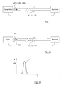
- FIG 1 In figure 1 is shown how line insertion loss is measured by a double ended line test in a laboratory.
- a transmitting device 1 is connected to a receiving measurement device 2 via a reference transmission line L1 for telecommunication purposes to be measured.
- the transmitting device sends a signal S(f1) of a frequency f1 having a specified output amplitude and the measurement device 2 measures a received attenuated amplitude of the signal S(f1).
- the line insertion loss L11 normally expressed in decibel dB, for the transmission line L1 at the frequency f1 is determined.
- the line insertion loss is measured with signals S (f2) ...S (fN) for further frequencies f2...fN.
- For the reference transmission line L1 there now is a set of line insertion loss values L11...L1N for the set of frequencies f1...fN.
- a reference transmission line L2 is measured giving a set of line insertion loss values L21...L2N for the set of frequencies f1...fN.
- Further reference transmission lines L3, L4,...., LK of different types and different lengths are measured in the same manner.
- FIG 2a a TDR measurement device 3 connected to a remote device 4 via the reference transmission line L1.
- the remote device is in this embodiment simply an open line end and the TDR measurement device 3 transmits a test signal P1, in the embodiment a pulse, to the line L1.
- the pulse is shown in the diagram in figure 2b with time t on the abscissa and amplitude A in dB on the ordinate.
- the test signal P1 is reflected at the remote device and a reflected signal P2 is measured by the TDR measurement device 3.
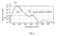
- the reflected signal is shown in figure 3 , which figure also is a diagram with the time t on the abscissa and the amplitude A in dB on the ordinate.
- the reflected signal P2 has both a first peak P21, which is recognized as the near end reflection, and an attenuated second peak P22, which is recognized as the far-end TDR reflection or far-end reflection from the open end in the remote device 4.
- the second peak P22 has a peak amplitude value that is denoted PV1 for the measured reference transmission line L1 and is a calibration quantity for this line.
- the peak value PV1 of the far-end reflection is related to the line insertion loss values L11, L12, whil, L1N for the reference transmission line L1 since the pulse P1 has traversed the loop twice (transmission line L1 back and forth).
- a line model of the transmission lines can be set up, which line model is calibrated with the aid of the line insertion loss values and the peak values for the reference transmission lines.
- the peak value in the embodiment is measured in dB it is compared to a reference value RV.
- the TDR measurement described in connection with figures 2a and 2b is performed also for the reference transmission lines L2,... , LK.
- Corresponding peak values PV2, ..., PVK, the calibration quantities, of the far-end reflection of the pulse P1 are generated and are compared to the reference value RV.
- Figure 4 demonstrates how the peak values of the far-end TDR reflections are related to the line insertion loss values.
- the figure is a diagram with the peak values from the TDR measurements on the abscissa and the laboratory measured line insertion loss on the ordinate.
- the peak values are generally denoted by PV and the line insertion loss is generally denoted by IL(f), where f denotes the frequency dependence.
- the values on both the axes are given in decibel dB.
- the corresponding peak values PV1 to PV5 are denoted on the abscissa.
- the corresponding line insertion loss values L11...L14, L21...L24 and so on are denoted.
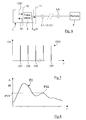
- Figure 5 shows a customer transmission line LX.
- the transmission line which has unknown line insertion loss, is connected to a line card 5 in the near end and a remote device 6 in the far-end.
- the remote device represents in this embodiment an open line end as earlier.
- the near end of the transmission line is disconnected from the line card 5 and is connected galvanic to the TDR measurement device 3.
- the test signal P1 is transmitted and a peak value PVX of the far-end TDR reflection is measured and is the calibration quantity for the customer transmission line LX.
- the peak value PVX is as earlier compared to the reference value RV.
- the calibration measurements are performed in the same manner for both the reference transmission lines and the customer transmission line. Therefore it is not necessary to know the amplitude of the transmitted signal P1, only the amplitude peak value of the far-end reflection is significant.
- c 1 (f), c 2 (f) and c 3 (f) are frequency dependent line model parameters.
- the line insertion loss values for any one of the frequencies in figure 4 can thus be interconnected by a polynomial of predetermined order.
- the line is adapted to the measured values by e.g. a least square algorithm.
- the remote device 4 or 6 was an open line end, i.e. the line termination had an unlimited impedance. Also other predetermined impedance values of the line termination are possible.
- One option is a short-circuit, another option is an impedance that is matched to the line impedance, in many cases around 100 ohms. In the latter case the best result is achieved when the line termination impedance is known and there also exist well known methods to estimate this impedance.
- the line termination has it is essential for very accurate results that it is the same predetermined termination impedance for both the reference transmission lines and the customer transmission line when calibrating the line model and measuring on the customer transmission line. It should anyhow be noted that the line model will give fully acceptable values for the customer transmission line insertion loss even if the line model was calibrated with a line termination impedance different from the line termination impedance of the actual customer transmission line.
- the line model will be calibrated in different editions with a predetermined line termination impedance for each edition.
- its termination impedance is determined and the corresponding edition of the line model is selected.
- the selected line model edition is then used when estimating the customer transmission line insertion loss.
- the TDR measurement device 3 was connected galvanic to the customer transmission line LX.
- a direct galvanic connection is not necessary and an option is e.g. to connect the measurement device via a transformer.
- Figure 5 also shows that the measurement device is connected at the station side of the line but the customer transmission line can as well be measured from its customer side.
- Figure 4 is a diagram in which the values on both the abscissa and the ordinate are denoted in decibel and the equations 1,2,4 and 5 all include the logarithmic function. This is not the only option, the line model can be formed in other ways with e.g. linear peak values.
- the line model for the transmission lines is presented as lines in a diagram and it is also presented as polynomials in equations (1) to (5).
- a further option to present the line model is in form of a table with the peak values PV1, PV2... and the line insertion loss values L11, L12 ... , L21, L22... etc.
- the line insertion loss for the customer transmission line LX is estimated by interpolation in the table.
- the alternative way of measuring the line insertion loss includes in broad outline the same operations as the method described in connection with figures 1-5 : Double ended laboratory measurements on the reference transmission lines, calibration SELT measurements on the same lines, generating of the line model, e.g. the curves in the Peak Value-Insertion Loss diagram, SELT measurements on the unknown customer transmission line and generating line insertion loss for the customer transmission lines.
- a difference is that instead of measuring directly the peak value PV1 of the second peak P22, the far-end TDR reflection, a calibration quantity is measured that substantially represents the peak value of the far-end TDR reflection.
- Figure 6 depicts a situation for performing a calibration measurement on the transmission lines L1, L2, L3,..., LK.
- the figure shows a line card 7 connected via the transmission line L1 to a remote device 8, which in the embodiment is an open line end.
- the line card 7 is exactly the same type as the line card that is used when transmitting services to the customers.
- the line card 7 has a transceiver 9 connected to the transmission line L1 and has also an interface 10.
- a test signal CS1 is sent to the line via the interface 10 and a reflected signal R1 is measured via the interface.
- a signal like the pulse P1 is not necessarily used.
- the test signal CS1 is a line spectrum signal which is continuous in time and which has a number of selected frequencies.
- the test signal CS1 is shown in figure 7 , which is a diagram with the frequency f on the abscissa and the amplitude CA on the ordinate.
- the test signal CS1 includes frequencies Cf1, whil, CfP which e.g. can be the DSL frequencies.
- the reflected signal R1 is measured in the time domain and is Fourier transformed into a signal CR1 in the frequency domain.
- H echo f CR 1 / CS 1
- an impulse response IP2 for the reference transmission line L1 in combination with the transceiver 9 is received.
- the impulse response IP2 is shown in figure 8 and is similar to the reflected pulse P2 in figure 3 .
- Figure 8 is a diagram with the time t on the abscissa and the amplitude A in dB on the ordinate.
- the impulse response IP2 has both a first peak which is recognized as the near end reflection, and an attenuated second peak IP22, which is recognized as the far-end echo from the open end in the remote device 8.
- the amplitude of the second peak has a peak value IPV1 which is a calibration quantity for the reference transmission line L1 that substantially represents the amplitude of a far-end TDR reflection.
- IPV1 is measured in dB on a logarithmic scale it is compared to a reference value RV1.
- the other reference transmission lines L2, L3 ... are calibrated giving far-end reflections with peak values IPV2, IPV3,....
- FIG. 9 a calibration diagram similar to figure 4 can be drawn as shown in figure 9 .
- the figure is a diagram with peak amplitude on the abscissa, generally denoted IPV.
- the line insertion loss IL(f) for the reference transmission lines L1, L2,... is denoted in dB on the ordinate.
- Points for the laboratory measured line insertion loss values L11...L14, ..., L51...L54 are plotted in the diagram for the corresponding peak amplitudes IPV1... IPV5, in the same manner as in figure 4 .
- Straight lines, one for each of the frequencies f1... f4, are adapted to the plotted points.
- the line insertion loss for the initially unknown customer transmission line LX is generated in the following manner. It is presumed that the transmission line LX is a real customer line and that the measurement takes place in the field.
- the line spectrum test signal CS1 is transmitted via the transceiver interface 10 and the reflected signal R1 is measured.
- a peak value IPVX for the customer transmission line LX is generated as described above and is the calibration quantity for the customer transmission line.
- Corresponding insertion loss values ILX1...ILX4 are read in the diagram for the customer transmission line LX.
- the measurement described above can give an accurate insertion loss value since it is a calibration measurement in which both the reference lines and the customer transmission line are measured in the same manner.
- frequencies f1...fN of the laboratory insertion loss measurements need in no way be the same as the frequencies Cf1...CfP of the line spectrum signal CS1.
- test signal CS1 is a line spectrum signal.
- other broadband test signals can be used to generate the echo path transfer function H echo (f).
- the line card 7 in figure 6 can be replaced by a Digital Subscriber Line Access Multiplexor DSLAM or a Customer Premises Equipment CPE.
- An impulse response similar to the impulse response IP2 of figure 8 can be generated also from a frequency dependent line input impedance Z in (f) for e.g. the line L1 or LX at an interface 11 in figure 6 .
- the parameters to the right are pre-stored transceiver model calibration values which are to be interpreted in the following manner:
- the value Z hyb ( f ) is the transceiver impedance as measured at the connections to the line L1, i.e. the transceiver impedance at the interface 11 as seen from the line side.
- a further possibility to generate an impulse response is to use a frequency dependent scattering parameter S 11 (f).
- S 11 f
- An example on how this parameter is generated is to be found in a standardization paper by Thierry Pollet :"How is G.selt to specify S11 (calibrated measurements)?", ITU Telecommunication Standardization Sector, Temporary Document OJ-091; Osaka, Japan 21-25 October, 2002 .
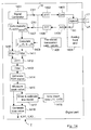
- Figure 10 is a flow chart that shows the method of estimating the line insertion loss for customer transmission lines.
- the method starts with a step 101, in which the line insertion loss IZ(f) is measured for the reference transmission lines L1...ZK.
- the measurement is performed in the double ended line test of figure 1 for the set of frequencies f1...fN.
- a method is selected for pre-measuring the calibration quantity of the reference transmission lines.
- One method is the TDR method described in connection with figures 2a,2b and 3 .
- Another method is that described in connection with figures 6 and 7 , using the continuous line spectrum test signal CS1 or another broadband signal.
- the echo path transfer function H echo (f) is generated.
- Still other methods are described using the line input impedance Z in (f) or the scattering parameter S 11 (f).
- the calibration quantity is pre-measured for the reference transmission lines in a step 103.
- the calibration quantity is the directly measured peak value PV1...PVK of the far-end TDR reflection.
- the method with the echo path transfer function H echo (f) is selected the peak value of the far-end echo for the reference transmission lines is generated.
- the reflected signal R1 is measured, this signal is Fourier transformed into the signal CR1, the echo path transfer function H echo (f) is generated and the impulse response IP2 is generated by applying the inverse Fourier transform.
- the echo path transfer function H echo (f) or the impulse response IP2 or the two of them are filtered.
- the peak value IPV1 is measured from the impulse response IP2 and is the calibration quantity.
- the relationship between the line insertion loss for the different frequencies and the peak value is generated in a step 104 for the reference transmission lines. This can be performed by e.g. the equations (1)-(5) or the diagrams of figures 4 or 9 .
- a step 105 the calibration quantity PVX, IPVX for the customer transmission line LX is measured in the same manner as in the step 103.
- the reference transmission lines and the customer transmission line must naturally be handled by the same method for the calibration to work properly.
- the line insertion loss for the customer transmission line LX is estimated in a step 106.
- the estimation is performed for the set of frequencies f1...fN with the aid of the diagram in figures 4 or 9 or the equations (1)-(5) of appropriate order.
- step 111 in which the TDR measurement device 3 or the line card 7 is connected to a selected one of the transmission lines, either one of the reference transmission lines L1...LK or the customer transmission line LX.
- test signal P1 or the broadband test signal e.g. the line spectrum test signal CS1 is transmitted at the near end of the selected transmission line.
- the reflected signal, P2 or IP2, reflected at the far-end of the transmission line in question, is received at the near end of that transmission line in a step 113.
- a signal corresponding to the TDR signal is generated in a step 114. Either the reflected signal P2 is received directly or the impulse response IP2 is generated as described above.
- the calibration quantity, the peak value representing the far-end TDR reflection is generated in a step 115.
- a step 116 it is investigated whether at least two of the reference transmission lines L1...LK and the customer transmission line have been handled. In an alternative YES the method ends in a step 117. In an alternative NO a further transmission line is selected in a step 118 and the steps 111-116 are repeated.
- the step 115 of generating the calibration quantity will be more closely described in connection with figure 12 .
- the figure shows the method with the broadband signal.
- the broadband test signal e.g. the line spectrum test signal CS1
- the line card 7 is transmitted via the line card 7.
- the signal R1 reflected at the far-end 8 of the transmission line is received via the line card and is recorded in a step 122.
- the reflected signal R1 which is in the time domain, is Fourier transformed into the frequency domain in a step 123.
- a step 124 the echo path transfer function H echo (f) is generated.
- the line input impedance Z in (f) or the scattering parameter S 11 (f) can be generated.
- the echo path transfer function H echo (f) (or Z in (f) or S 11 ) is, as one alternative, filtered in a step 125
- the impulse response IP2 for the transmission line is generated in a step 126 by applying the inverse Fourier transform on either the echo path transfer function H echo (f), the line input impedance Z in (f) or the scattering parameter S 11 (f).
- a step 127 the impulse response IP2 is filtered in a second alternative. It is not necessary to perform the steps 125 or 127 but is an enhancement and both of them can be performed.
- a step 128 the calibration quantity, the amplitude peak value IPV1 of the far-end reflection, is measured.
- a step 131 the far-end peak values PV1,PV2... or alternatively IPV1,IPV2... for the reference transmission lines L1...LK are compared to the reference value RV or alternatively RV1.
- the logarithms of the thus achieved quotients are generated in a step 132.
- a step 133 the points L11...L51 are generated which are determined by the logarithms of step 132 and the pre-measured line insertion loss for a selected one of the frequencies f1.
- the step 133 is repeated for the other frequencies f2...fN.
- a polynomial per frequency is adapted to the points of step 133, thus defining an example of the line model for the transmission lines.
- step 135 the line insertion loss LX1, alternatively ILX1, for the customer transmission line LX is estimated according to step 106 in figure 10 . Its logarithmic value, generated according to step 132, is inserted in the polynomial for the selected frequency f1. Step 135 is repeated for the frequencies f2...fN.
- FIG 14 shows in more detail the line card 7 in figure 6 .
- the line card has an analog front end 1404 with a hybrid circuit and a digital part.
- the latter includes a signal generator 1401 transmitting the test signal CS1, which is transformed in an inverse Fourier transformer 1402 into the time domain.
- the transformed signal is digital to analog converted in a D/A converter 1403, sent to the hybrid circuit and is transmitted on the line, e.g. the reference transmission line L1 or the customer transmission line LX.
- the transmitted signal is reflected at the far-end of the line, is received by the hybrid circuit and is analog to digital converted in an A/D converter 1405 into the reflected signal R1.
- a Fourier transformer 1406 transforms the reflected signal R1 into the received signal CR1 in the frequency domain and leaves it to an echo transfer function device 1407.
- the echo path transfer function H echo (f) is generated with the use of the test signal CS1 and the received signal CR1.
- the echo path transfer function H echo (f) is delivered to a filter 1410 or, in alternative embodiments, to a calculating device 1409.
- the latter is connected to a store 1408 which pre-stores the transceiver model calibration values and calculates either the line input impedance Z in (f) or the scattering parameter S 11 (f), which is delivered to a filter 1411.
- the output from either the filter 1410 or the filter 1411 is delivered to the inverse Fourier transformer 1412.
- the impulse response IP2 is generated in the inverse Fourier transformer, which sends the impulse response to a filter 1413.
- the filtering is not necessary but enhances the result.
- the filters both before and after the inverse Fourier transformer 1412 can be utilized.
- the output from the filter 1413 is delivered to a calculation circuit 1415. This circuit recognizes the far-end reflection IP22 of the impulse response and in a measuring device 1415 the amplitude peak value IPV1, i.e. the calibration quantity, is measured.
- the peak values are sent to a model circuit 1417.
- This circuit stores the peak values and calibrates the line model.
- the polynomial of equation (1) is the line model the polynomial is adapted to the points determined by the peak values and the pre-measured line insertion loss values L11... LKN for the different frequencies f1...fN.
- the line insertion loss values are received from a store 1416.
- the amplitude peak values are simply stored in the model circuit 1417.
- the amplitude peak value IPVX for this line is sent to a loss value generating circuit 1418, which also receives the calibrated line model from the model circuit 1417.
- the loss value generating circuit 1418 the amplitude peak value for the customer transmission line LX is inserted in the line model for the different frequencies f1...fN and the line insertion loss values LX1...LXN are obtained for the customer transmission line LX.
- the circuit 1418 inserts the amplitude peak value IPVX for the customer transmission line LX in the polynomial and outputs the insertion loss values ILX1, ILX2.
- the circuit 1418 interpolates in the calibrated line model with the help of amplitude peak value IPVX for the customer transmission line LX.
Landscapes
- Engineering & Computer Science (AREA)
- Computer Networks & Wireless Communication (AREA)
- Signal Processing (AREA)
- Measurement Of Resistance Or Impedance (AREA)
- Monitoring And Testing Of Transmission In General (AREA)
- Cable Transmission Systems, Equalization Of Radio And Reduction Of Echo (AREA)
- Telephonic Communication Services (AREA)
Claims (27)
- Procédé, mis en oeuvre dans le domaine des télécommunications, d'estimation de perte d'insertion de ligne d'une ligne de transmission cliente (LX) à au moins une fréquence (f1), le procédé incluant les étapes suivantes consistant à :- mesurer au préalable des valeurs de perte d'insertion de ligne (L11, ..., L1N) pour au moins deux lignes de transmission de référence (L1, ..., LK) à ladite au moins une fréquence (f1) ;caractérisé en ce qu'il comporte les étapes ci-dessous consistant à :- mesurer au préalable une quantité d'étalonnage (PV1, ..., IPV1...) pour chacune desdites au moins deux lignes de transmission de référence (L1, ..., LK), laquelle quantité d'étalonnage représente sensiblement l'amplitude d'une réflexion TDR à distance ;- mesurer ladite quantité d'étalonnage (PVX, IPVX) pour ladite ligne de transmission cliente de télécommunication (LX) ;- générer une estimation de la perte d'insertion de ligne (LX1, ..., ILX1, ...) à chacune de ladite au moins une fréquence (f1) pour la ligne de transmission cliente (LX) selon un modèle de ligne, le modèle de ligne incluant ladite perte d'insertion de ligne mesurée au préalable (L11, ..., L1N) et étant étalonné par ladite quantité d'étalonnage (PV1, ..., IPV1...) des lignes de transmission de référence (L1-LK), et l'estimation étant générée en fonction de ladite quantité d'étalonnage (PVX, IPVX) de la ligne de transmission cliente (LX).
- Procédé d'estimation de perte d'insertion de ligne selon la revendication 1, dans lequel l'étape consistant à mesurer au préalable la quantité d'étalonnage pour les lignes de transmission de référence inclut les étapes ci-dessous consistant à :- a) transmettre un signal de test (P1, CS1) au niveau d'une extrémité proche des lignes de transmission de référence (L1, ..., LK) ;- b) recevoir un signal réfléchi (P2, R1) au niveau de l'extrémité proche des lignes de transmission de référence (L1, ..., LK), le signal étant réfléchi au niveau d'une extrémité distante (4, 8) des lignes de transmission de référence présentant une terminaison de ligne d'une impédance prédéterminée ;- c) générer un signal (P2, IP2) correspondant sensiblement à la réflexion TDR des lignes de transmission de référence.
- Procédé d'estimation de perte d'insertion de ligne selon la revendication 1, dans lequel l'étape de mesure de la quantité d'étalonnage pour la ligne de transmission cliente (LX) inclut les étapes ci-dessous consistant à :- a1) transmettre un signal de test (P1, CS1) à une extrémité proche de la ligne de transmission cliente (LX) ;- b1) recevoir un signal réfléchi (P2, R1) au niveau de l'extrémité proche de la ligne de transmission cliente (LX), le signal étant réfléchi au niveau d'une extrémité distante (6, 8) de la ligne de transmission cliente présentant une terminaison de ligne d'une impédance prédéterminée ;- c1) générer un signal (P2, IP2) correspondant sensiblement à la réflexion TDR de la ligne de transmission cliente (LX).
- Procédé d'estimation de perte d'insertion de ligne selon la revendication 2, dans lequel :- le signal de test de l'étape a) est une impulsion (P1) qui est connectée à l'extrémité proche de la ligne de transmission de référence (L1, ..., LK) ;- le signal réfléchi (P2) de l'étape b) est la réflexion TDR ;- la quantité d'étalonnage est la valeur de crête d'amplitude (PV1) de la réflexion TDR à l'extrémité distante (P22).
- Procédé d'estimation de perte d'insertion de ligne selon la revendication 3, dans lequel :- le signal de test de l'étape a1) est une impulsion (P1) qui est connectée à l'extrémité proche de la ligne de transmission cliente (LX) ;- le signal réfléchi (P2) de l'étape b1) est la réflexion TDR ;- la quantité d'étalonnage est la valeur de crête d'amplitude (PVX) de la réflexion TDR à distance (P22).
- Procédé d'estimation de perte d'insertion de ligne selon la revendication 2, dans lequel :- le signal de test de l'étape a) est un signal à large bande (CS1) qui est transmis par l'intermédiaire d'une carte de ligne (7) ;- le signal réfléchi (R1) de l'étape b) est un signal dans le domaine temporel qui est reçu par l'intermédiaire de la carte de ligne ;- la génération du signal (IP2) de l'étape c) inclut les étapes ci-dessous consistant à :- e) transformer, par transformée de Fourier, le signal réfléchi (R1), en un signal (CR1) dans le domaine fréquentiel ;- f) générer une fonction de transfert de trajet d'écho (Hecho (f)) pour la ligne de transmission de référence, en utilisant le signal à large bande (CS1) et le signal réfléchi (CR1) transformé par transformée de Fourier;- g) générer une réponse impulsionnelle (IP2) pour la ligne de transmission de référence, en appliquant la transformée de Fourier inverse sur la fonction de transfert de trajet d'écho (Hecho (f)) ;- la quantité d'étalonnage est la valeur de crête d'amplitude (IPV1) de la réflexion à l'extrémité distante (IP22) de la réponse impulsionnelle (IP2).
- Procédé d'estimation de perte d'insertion de ligne selon la revendication 3, dans lequel :- le signal de test de l'étape a1) est un signal à large bande (CS1) qui est transmis par l'intermédiaire d'une carte de ligne (7) ;- le signal réfléchi (R1) de l'étape b1) est un signal dans le domaine temporel qui est reçu par l'intermédiaire de la carte de ligne ;- la génération du signal (IP2) de l'étape c1) inclut les étapes ci-dessous consistant à :- e) transformer, par transformée de Fourier, le signal réfléchi (R1), en un signal (CR1) dans le domaine fréquentiel ;- f) générer une fonction de transfert de trajet d'écho (Hecho (f)) pour la ligne de transmission cliente, en utilisant le signal à large bande (CS1) et le signal réfléchi transformé par transformée de Fourier (CR1) ;- g) générer une réponse impulsionnelle (IP2) pour la ligne de transmission cliente, en appliquant la transformée de Fourier inverse sur la fonction de transfert de trajet d'écho (Hecho (f)) ;- la quantité d'étalonnage est la valeur de crête d'amplitude (IPV1) de la réflexion à l'extrémité distante (IP22) de la réponse impulsionnelle (IP2).
- Procédé d'estimation de perte d'insertion de ligne selon la revendication 2, dans lequel :- le signal de test de l'étape a) est un signal à large bande (CS1) qui est transmis par l'intermédiaire d'une carte de ligne (7) ;- le signal réfléchi (R1) de l'étape b) est un signal dans le domaine temporel qui est reçu par l'intermédiaire de la carte de ligne ;- la génération du signal (IP2) de l'étape c) inclut les étapes ci-dessous consistant à :- e) transformer, par transformée de Fourier, le signal réfléchi (R1), en un signal (CR1) dans le domaine fréquentiel ;- h) générer une impédance d'entrée de ligne (Zin (f)) pour la ligne de transmission de référence, en utilisant le signal à large bande (CS1) et le signal réfléchi (CR1) transformé par transformée de Fourier;- i) générer une réponse impulsionnelle pour la ligne de transmission de référence, en appliquant la transformée de Fourier inverse sur l'impédance d'entrée de ligne (Zin(f)) ;- la quantité d'étalonnage est la valeur de crête d'amplitude de la réflexion à l'extrémité distante de la réponse impulsionnelle.
- Procédé d'estimation de perte d'insertion de ligne selon la revendication 3, dans lequel :- le signal de test de l'étape a1) est un signal à large bande (CS1) qui est transmis par l'intermédiaire d'une carte de ligne (7) ;- le signal réfléchi (R1) de l'étape b1) est un signal dans le domaine temporel qui est reçu par l'intermédiaire de la carte de ligne ;- la génération du signal (IP2) de l'étape c1) inclut les étapes ci-dessous consistant à :- e) transformer, par transformée de Fourier, le signal réfléchi (R1), en un signal (CR1) dans le domaine fréquentiel ;- h) générer une impédance d'entrée de ligne (Zin (f)) pour la ligne de transmission cliente, en utilisant le signal à large bande (CS1) et le signal réfléchi (CR1) transformé par transformée de Fourier;- i) générer une réponse impulsionnelle pour la ligne de transmission cliente, en appliquant la transformée de Fourier inverse sur l'impédance d'entrée de ligne (Zin(f)) ;- la quantité d'étalonnage est la valeur de crête d'amplitude de la réflexion à l'extrémité distante de la réponse impulsionnelle.
- Procédé d'estimation de perte d'insertion de ligne selon la revendication 2, dans lequel :- le signal de test de l'étape a) est un signal à large bande (CS1) qui est transmis par l'intermédiaire d'une carte de ligne (7) ;- le signal réfléchi (R1) de l'étape b) est un signal dans le domaine temporel qui est reçu par l'intermédiaire de la carte de ligne ;- la génération du signal (IP2) de l'étape c) inclut les étapes ci-dessous consistant à :- e) transformer, par transformée de Fourier (R1), le signal réfléchi (R1), en un signal (CR1) dans le domaine fréquentiel ;- k) générer un paramètre de dispersion (S11 (f)) pour la ligne de transmission de référence, en utilisant le signal à large bande (CS1) et le signal réfléchi (CR1) transformé par transformée de Fourier;- l) générer une réponse impulsionnelle pour la ligne de transmission de référence, en appliquant la transformée de Fourier inverse sur le paramètre de dispersion (S11 (f)) ;- la quantité d'étalonnage est la valeur de crête d'amplitude de la réflexion à l'extrémité distante de la réponse impulsionnelle.
- Procédé d'estimation de perte d'insertion de ligne selon la revendication 3, dans lequel :- le signal de test de l'étape a1) est un signal à large bande (CS1) qui est transmis par l'intermédiaire d'une carte de ligne (7) ;- le signal réfléchi (R1) de l'étape b1) est un signal dans le domaine temporel qui est reçu par l'intermédiaire de la carte de ligne ;- la génération du signal (IP2) de l'étape c1) inclut les étapes ci-dessous consistant à :- e) transformer, par transformée de Fourier, le signal réfléchi (R1), en un signal (CR1) dans le domaine fréquentiel ;- k) générer un paramètre de dispersion (S11 (f)) pour la ligne de transmission cliente, en utilisant le signal à large bande (CS1) et le signal réfléchi (CR1) transformé par transformée de Fourier;- 1) générer une réponse impulsionnelle pour la ligne de transmission cliente, en appliquant la transformée de Fourier inverse sur le paramètre de dispersion (S11 (f)) ;- la quantité d'étalonnage est la valeur de crête d'amplitude de la réflexion à l'extrémité distante de la réponse impulsionnelle.
- Procédé d'estimation de perte d'insertion de ligne selon l'une quelconque des revendications 6 à 11, dans lequel le signal à large bande (CS1) est un signal de spectre de ligne.
- Procédé d'estimation de perte d'insertion de ligne selon la revendication 2 ou 3, le procédé incluant les étapes ci-dessous consistant à :- étalonner différentes éditions du modèle de ligne (1), dans lequel différentes impédances de terminaison de ligne (4, 6, 8) sont utilisées pour les différentes éditions ;- sélectionner l'une des éditions pour la génération de la perte d'insertion de ligne de la ligne de transmission cliente (LX), dans lequel la ligne de transmission cliente et l'édition sélectionnée du modèle de ligne présentent essentiellement la même impédance de terminaison de ligne.
- Procédé d'estimation de perte d'insertion de ligne selon l'une quelconque des revendications 6 et 7, 8 et 9, ou 10 et 11, dans lequel l'un des éléments parmi la fonction de transfert de trajet d'écho (Hecho (f)), l'impédance d'entrée de ligne (Zin (f)) et le paramètre de dispersion (S11 (f)), est filtré en vue de simplifier la reconnaissance de la réflexion à l'extrémité distante de la réponse impulsionnelle (IP22).
- Procédé d'estimation de perte d'insertion de ligne selon l'une quelconque des revendications 6 et 7, 8 et 9, ou 10 et 11, dans lequel la réponse impulsionnelle (IP22) est filtrée en vue de simplifier la reconnaissance de sa réflexion à l'extrémité distante.
- Procédé d'estimation de perte d'insertion de ligne selon les revendications 1 à 15, incluant les étapes ci-dessous consistant à :- adapter un polynôme ((1)) d'ordre prédéterminé à des points déterminés à la fois par les valeurs de perte d'insertion de ligne mesurées au préalable (L11, L21, ...) desdites au moins deux lignes de transmission de référence (L1, L2, ...) pour ladite au moins une fréquence (f1, ..., fN), et par la quantité d'étalonnage correspondante mesurée au préalable (PV1, PV2, ... ; IPV1, IPV2, ...) pour les lignes de transmission de référence ; et- estimer la perte d'insertion de ligne (IL (f)) de la ligne de transmission cliente (LX), en insérant sa quantité d'étalonnage (PVX ; IPVX) dans ledit polynôme.
- Procédé d'estimation de perte d'insertion de ligne selon la revendication 16, dans lequel la variable indépendante du polynôme est le logarithme de ladite valeur de crête (PV) comparée à une valeur de référence (RV ; RV1).
- Procédé d'estimation de perte d'insertion de ligne selon la revendication 16, dans lequel le polynôme est du premier ordre, à savoir une ligne droite (Lf1, Lf2, ...).
- Agencement, mis en oeuvre dans le domaine des télécommunications, apte à estimer une perte d'insertion de ligne d'une ligne de transmission cliente (LX) à au moins une fréquence (f1), l'agencement comprenant :- un moyen (1416) pour stocker des valeurs mesurées au préalable de perte d'insertion de ligne (L11, ..., L1N) pour au moins deux lignes de transmission de référence (L1, ..., LK) à ladite au moins une fréquence (f1) ;caractérisé par :- un moyen (1401, 1406, 1407, 1410-1415) pour mesurer une quantité d'étalonnage (PV1, ..., IPV1, ... ; PVX, IPVX) pour chacune desdites au moins deux lignes de transmission de référence (L1, ..., LK) et ladite ligne de transmission cliente (LX), laquelle quantité d'étalonnage représente sensiblement l'amplitude d'une réflexion TDR à l'extrémité distante ;- un moyen (1416-1418) pour estimer la perte d'insertion de ligne (LX1, ..., ILX1, ...) à chacune de ladite au moins une fréquence (f1) pour la ligne de transmission cliente (LX), en fonction de ladite perte d'insertion de ligne mesurée au préalable (L11, ..., L1N) et de ladite quantité d'étalonnage (PV1, ..., IPV1, ...) des lignes de transmission de référence (L1-LK) et de la quantité d'étalonnage (PVX, IPVX) de la ligne de transmission cliente (LX).
- Agencement pour estimer une perte d'insertion de ligne selon la revendication 19, dans lequel le moyen pour mesurer la quantité d'étalonnage inclut :- un générateur de signal (1401) destiné à transmettre un signal (P1, CS1) à une extrémité proche des lignes de transmission de référence (L1-LK) et de la ligne de transmission cliente (LX) ;- un moyen (1404, 1406) pour recevoir un signal réfléchi (P2, R1) au niveau de l'extrémité proche des lignes de transmission de référence (L1-LK) et de la ligne de transmission cliente (LX), le signal étant réfléchi au niveau d'une extrémité distante (4, 6) des lignes de transmission présentant une terminaison de ligne d'une impédance prédéterminée ;- un moyen (1407, 1410, 1412, 1414) pour générer un signal (P2, IP2) correspondant sensiblement à la réflexion TDR à l'extrémité distante de la ligne de transmission cliente (LX) et des lignes de transmission de référence (L1, ..., LK) ; et- un dispositif de mesure (1415) destiné à mesurer la valeur de crête d'amplitude (PV1, IPV1) de la réflexion TDR à l'extrémité distante (P22, IP22).
- Agencement pour estimer une perte d'insertion de ligne selon la revendication 20, lequel agencement inclut une carte de ligne (7), la carte de ligne incluant en outre :- le générateur de signal (1401), lequel est agencé de manière à transmettre un signal à large bande (CS1) ;- le moyen pour recevoir le signal réfléchi (R1), lequel moyen reçoit le signal réfléchi dans le domaine temporel et inclut un frontal analogique (1404) ;- un transformateur de Fourier (1406) pour transformer le signal réfléchi (R1) en un signal correspondant (CR1) dans le domaine fréquentiel ;- un dispositif à fonction de transfert d'écho (1407) destiné à générer une fonction de transfert de trajet d'écho (Hecho (f)) pour les lignes de transmission de référence (L1, ..., LK) et la ligne de transmission cliente (LX), en utilisant le signal à large bande (CS1) et le signal réfléchi (CR1) transformé par transformée de Fourier.
- Agencement pour estimer une perte d'insertion de ligne selon la revendication 21, la carte de ligne (7) incluant en outre :- un transformateur de Fourier inverse (1412) destiné à générer une réponse impulsionnelle (IP2) pour les lignes de transmission de référence (L1, ..., LK) et la ligne de transmission cliente (LX), en appliquant la transformée de Fourier inverse sur la fonction de transfert de trajet d'écho (Hecho (f)) ;- un moyen (1414, 1415) pour générer la quantité d'étalonnage, laquelle est la valeur de crête d'amplitude (IPV1) de la réflexion TDR à l'extrémité distante (IP22) de la réponse impulsionnelle (IP2) de la fonction de transfert de trajet d'écho.
- Agencement pour estimer une perte d'insertion de ligne selon la revendication 21, la carte de ligne (7) incluant en outre :- un magasin de stockage (1408) qui stocke au préalable des valeurs d'étalonnage de modèle d'émetteur-récepteur ;- un dispositif de calcul destiné à générer une impédance d'entrée de ligne (Zin (f)) pour les lignes de transmission de référence (L1, ..., LK) et la ligne de transmission cliente (LX), en utilisant la fonction de transfert de trajet d'écho (Hecho (f)) ;- un transformateur de Fourier inverse (1412) destiné à générer une réponse impulsionnelle (IP2) pour les lignes de transmission de référence (L1, ..., LK) et la ligne de transmission cliente (LX), en appliquant la transformée de Fourier inverse sur l'impédance d'entrée de ligne (Zin (f)) ;- un moyen (1414, 1415) pour générer la quantité d'étalonnage, laquelle est la valeur de crête d'amplitude (IPV1) de la réflexion TDR à l'extrémité distante (IP22) de la réponse impulsionnelle (IP2) de l'impédance d'entrée de ligne.
- Agencement pour estimer une perte d'insertion de ligne selon la revendication 21, la carte de ligne (7) incluant en outre :- un magasin de stockage (1408) qui stocke au préalable des valeurs d'étalonnage de modèle d'émetteur-récepteur ;- un dispositif de calcul destiné à générer un paramètre de dispersion (S11 (f)) pour les lignes de transmission de référence (L1, ..., LK) et la ligne de transmission cliente (LX), en utilisant la fonction de transfert de trajet d'écho (Hecho (f)) ;- un transformateur de Fourier inverse (1412) destiné à générer une réponse impulsionnelle (IP2) pour les lignes de transmission de référence (L1, ..., LK) et la ligne de transmission cliente (LX), en appliquant la transformée de Fourier inverse sur le paramètre de dispersion (S11 (f)) ;- un moyen (1414, 1415) pour générer la quantité d'étalonnage, laquelle est la valeur de crête d'amplitude (IPV1) de la réflexion TDR à l'extrémité distante (IP22) de la réponse impulsionnelle (IP2) du paramètre de dispersion.
- Agencement pour estimer une perte d'insertion de ligne selon la revendication 22, 23 ou 24, la carte de ligne (7) incluant en outre un filtre (1410, 1411) destiné à filtrer l'un des éléments parmi la fonction de transfert de trajet d'écho (Hecho (f)), l'impédance d'entrée de ligne (Zin (f)) et le paramètre de dispersion (S11 (f)).
- Agencement pour estimer une perte d'insertion de ligne selon la revendication 22, 23 ou 24, la carte de ligne (7) incluant en outre un filtre (1413) destiné à filtrer la réponse impulsionnelle (P2, IP2).
- Agencement pour estimer une perte d'insertion de ligne selon la revendication 24, 25 ou 26, la carte de ligne (7) incluant :- un magasin de stockage (1416) destiné à stocker les valeurs de perte d'insertion de ligne mesurées au préalable (L11, ..., LKN) ;- un circuit de modèle (1417) destiné à stocker les valeurs de crête d'amplitude (IPV1, IPV2, ...) des lignes de transmission de référence (L1-LK) et à étalonner le modèle de ligne à l'aide des valeurs de crête d'amplitude et des valeurs de perte d'insertion (L11, ..., LKN) pour les lignes de transmission de référence ;- un circuit de génération de valeurs de perte (1418) lequel reçoit le modèle de ligne ((1) - (5)) et est agencé de manière à générer les valeurs de perte d'insertion de ligne (ILX1, ILX2, ...) pour la ligne de transmission cliente (LX) à l'aide du modèle de ligne et de la valeur de crête d'amplitude (IPVX) pour la ligne de transmission cliente (LX).
Applications Claiming Priority (2)
| Application Number | Priority Date | Filing Date | Title |
|---|---|---|---|
| US80700006P | 2006-07-11 | 2006-07-11 | |
| PCT/SE2007/000446 WO2008008015A2 (fr) | 2006-07-11 | 2007-05-08 | Estimation de la perte d'insertion d'une ligne de transmission |
Publications (3)
| Publication Number | Publication Date |
|---|---|
| EP2039018A2 EP2039018A2 (fr) | 2009-03-25 |
| EP2039018A4 EP2039018A4 (fr) | 2014-07-02 |
| EP2039018B1 true EP2039018B1 (fr) | 2016-03-09 |
Family
ID=38923705
Family Applications (1)
| Application Number | Title | Priority Date | Filing Date |
|---|---|---|---|
| EP07748110.9A Not-in-force EP2039018B1 (fr) | 2006-07-11 | 2007-05-08 | Estimation de la perte d'insertion d'une ligne de transmission |
Country Status (6)
| Country | Link |
|---|---|
| US (1) | US8265232B2 (fr) |
| EP (1) | EP2039018B1 (fr) |
| JP (1) | JP4824817B2 (fr) |
| CN (1) | CN101490970B (fr) |
| WO (1) | WO2008008015A2 (fr) |
| ZA (1) | ZA200810383B (fr) |
Cited By (1)
| Publication number | Priority date | Publication date | Assignee | Title |
|---|---|---|---|---|
| TWI712810B (zh) * | 2019-09-11 | 2020-12-11 | 英業達股份有限公司 | 檢測差動訊號之方法 |
Families Citing this family (26)
| Publication number | Priority date | Publication date | Assignee | Title |
|---|---|---|---|---|
| US8929472B1 (en) | 2006-07-26 | 2015-01-06 | Marvell International Ltd. | Bit-level combining for MIMO systems with HARQ and/or repetition coding |
| US9178990B2 (en) * | 2008-06-30 | 2015-11-03 | Ikanos Communications, Inc. | Systems and methods for characterizing loops based on single-ended line testing (SELT) |
| JP5151771B2 (ja) * | 2008-07-28 | 2013-02-27 | 富士通株式会社 | 信号伝送装置、信号伝送装置制御方法 |
| WO2010064977A1 (fr) * | 2008-12-01 | 2010-06-10 | Telefonaktiebolaget L M Ericsson (Publ) | Procédé pour l’analyse de ligne de transmission |
| EP2494700B1 (fr) | 2009-10-30 | 2015-10-21 | Telefonaktiebolaget L M Ericsson (PUBL) | Estimation à une extrémité unique de la télé-diaphonie, sur une ligne numérique d'abonné |
| IN2012DN02883A (fr) * | 2009-10-30 | 2015-07-24 | Ericsson Telefon Ab L M | |
| US8189702B1 (en) * | 2010-11-23 | 2012-05-29 | Ralink Technology Corp. | Scattering-parameter estimation method and transceiver using the same |
| EP2472281A1 (fr) * | 2011-01-03 | 2012-07-04 | Alcatel Lucent | Procédé et système pour étalonner une première méthode d'estimation de la valeur d'une caractéristique de boucle utilisant une première caractéristique de boucle localement mesurable et un premier ensemble de paramètres |
| US9360392B2 (en) * | 2013-06-28 | 2016-06-07 | Corning Cable Systems Llc | Calibration of optical time domain reflectometry optical loss measurement in optical fibers having potentially dissimilar light backscattering efficiencies |
| TWI594191B (zh) * | 2013-08-26 | 2017-08-01 | 緯創資通股份有限公司 | 識別系統、實體裝置、識別裝置及實體裝置的識別方法 |
| US9148504B2 (en) | 2013-10-14 | 2015-09-29 | Telefonaktiebolaget L M Ericsson (Publ) | Method and system for single-ended line testing |
| CN103530212A (zh) * | 2013-10-28 | 2014-01-22 | 浪潮电子信息产业股份有限公司 | 一种针对高速信号损耗测试的方法 |
| JP6230705B2 (ja) * | 2014-06-03 | 2017-11-15 | 三菱電機株式会社 | 伝送ケーブル特性測定装置及び伝送ケーブル特性測定方法 |
| US10684319B2 (en) | 2015-07-20 | 2020-06-16 | International Business Machines Corporation | Tuning a testing apparatus for measuring skew |
| US10162002B2 (en) | 2015-07-20 | 2018-12-25 | International Business Machines Corporation | Tuning a testing apparatus for measuring skew |
| US10151788B2 (en) | 2017-01-30 | 2018-12-11 | Savannah River Nuclear Solutions, Llc | Autonomously powered inductively coupled time domain reflectometer sensor device |
| CN106772187B (zh) * | 2017-03-13 | 2019-05-14 | 郑州云海信息技术有限公司 | 一种用于传输线损耗测试正确性的确定方法 |
| CN107144738B (zh) * | 2017-06-09 | 2020-10-27 | 中国电子科技集团公司第四十一研究所 | 一种基于直通线的多端口自动夹具损耗和相位补偿方法 |
| CN112204369B (zh) * | 2018-05-29 | 2022-11-18 | 住友电气工业株式会社 | 用于测量光纤的传输损耗的方法以及otdr测量装置 |
| CN108919057B (zh) * | 2018-08-07 | 2020-06-16 | 哈尔滨工业大学 | 一种对电缆故障诊断中插损问题的处理方法 |
| EP3876428A4 (fr) * | 2018-12-20 | 2021-11-24 | Mitsubishi Electric Corporation | Système de calcul de longueur de câble, dispositif de commande, et procédé de calcul de longueur de câble |
| CN109526019B (zh) * | 2018-12-26 | 2022-04-08 | 国网湖南省电力有限公司 | 基于实测数据的无线专网基站覆盖范围传播模型校正方法 |
| CN110261697B (zh) * | 2019-06-20 | 2022-04-15 | 中国电力科学研究院有限公司 | 处于实际运行工况的架空输电线路的线损计算方法及系统 |
| CN110940896B (zh) * | 2019-12-19 | 2022-03-11 | 裕太微电子股份有限公司 | 一种超长线缆的损伤诊断方法 |
| US11533105B1 (en) * | 2020-06-01 | 2022-12-20 | Cable Television Laboratories, Inc. | Systems and methods for determining reflection and transmission coefficients |
| CN113109658A (zh) * | 2021-06-16 | 2021-07-13 | 广东电网有限责任公司佛山供电局 | 一种线路损耗的分析方法及装置 |
Family Cites Families (17)
| Publication number | Priority date | Publication date | Assignee | Title |
|---|---|---|---|---|
| US5909978A (en) * | 1993-11-15 | 1999-06-08 | Porex Surgical Inc. | Marker pen |
| US5530367A (en) * | 1995-01-06 | 1996-06-25 | Fluke Corporaton | Pulse based cable attenuation measurement system |
| JP3237529B2 (ja) * | 1996-07-22 | 2001-12-10 | 安藤電気株式会社 | 伝送線路伝搬遅延時間測定装置 |
| EP0926841A3 (fr) | 1997-12-20 | 2003-07-09 | Nortel Networks Limited | Procédé et appareil d'essai de liaisons de communication |
| DE59800423D1 (de) * | 1998-07-09 | 2001-02-08 | Wandel & Goltermann Man Holdin | Verfahren zur Dämpfungsmessung in digitalen Übertragungsleitungen |
| FI981990A7 (fi) * | 1998-09-15 | 2000-03-16 | Nokia Corp | Mittausmenetelmä ja mittauslaite |
| JP2001074597A (ja) * | 1999-09-01 | 2001-03-23 | Sumitomo Electric Ind Ltd | 分岐光線路の試験方法及び試験装置付分岐光線路 |
| GB0005227D0 (en) * | 2000-03-03 | 2000-04-26 | Teradyne Inc | Technique for estimatio of insertion loss |
| FR2812947B1 (fr) * | 2000-08-11 | 2002-11-08 | Dassault Automatismes | Procede et dispositif de mesure de l'attenuation d'une ligne |
| ATE340439T1 (de) * | 2001-04-02 | 2006-10-15 | Cit Alcatel | Verfahren und gerät zur zugriffnetzwerkidentifikation durch 1- tormessungen |
| US6980007B1 (en) * | 2002-06-07 | 2005-12-27 | Marvell International Ltd. | Cable tester with insertion loss and return loss estimators |
| DE10226347C1 (de) * | 2002-06-13 | 2003-11-27 | Infineon Technologies Ag | Verfahren und Schaltungsanordnung zum Ermitteln von Übertragungsparametern |
| US6826258B2 (en) * | 2002-06-20 | 2004-11-30 | Teradyne, Inc. | System and method for pre-qualification of telephone lines for DSL service using an average loop loss |
| EP1411361B1 (fr) * | 2002-10-18 | 2006-03-22 | Alcatel | Prétraitement de signal pour évaluer des attributs d'une ligne de transmission |
| DE602004011333T2 (de) * | 2003-05-12 | 2009-01-08 | Telefonaktiebolaget Lm Ericsson (Publ) | Verfahren und anordnung für signalschleifentests |
| JP2004354125A (ja) * | 2003-05-28 | 2004-12-16 | Nippon Telegr & Teleph Corp <Ntt> | 光線路特性の解析方法及び光線路試験システム及び光線路試験監視システム |
| CN1943130A (zh) | 2004-02-11 | 2007-04-04 | 阿瓦雷公司 | 通信信道容量估计 |
-
2007
- 2007-05-08 EP EP07748110.9A patent/EP2039018B1/fr not_active Not-in-force
- 2007-05-08 US US12/373,303 patent/US8265232B2/en not_active Expired - Fee Related
- 2007-05-08 WO PCT/SE2007/000446 patent/WO2008008015A2/fr not_active Ceased
- 2007-05-08 CN CN200780026017.2A patent/CN101490970B/zh not_active Expired - Fee Related
- 2007-05-08 JP JP2009519404A patent/JP4824817B2/ja not_active Expired - Fee Related
-
2008
- 2008-12-08 ZA ZA2008/10383A patent/ZA200810383B/en unknown
Cited By (1)
| Publication number | Priority date | Publication date | Assignee | Title |
|---|---|---|---|---|
| TWI712810B (zh) * | 2019-09-11 | 2020-12-11 | 英業達股份有限公司 | 檢測差動訊號之方法 |
Also Published As
| Publication number | Publication date |
|---|---|
| EP2039018A2 (fr) | 2009-03-25 |
| CN101490970A (zh) | 2009-07-22 |
| WO2008008015A2 (fr) | 2008-01-17 |
| WO2008008015A3 (fr) | 2008-04-03 |
| JP4824817B2 (ja) | 2011-11-30 |
| US8265232B2 (en) | 2012-09-11 |
| ZA200810383B (en) | 2010-02-24 |
| US20090245476A1 (en) | 2009-10-01 |
| CN101490970B (zh) | 2013-01-02 |
| JP2009543511A (ja) | 2009-12-03 |
| EP2039018A4 (fr) | 2014-07-02 |
Similar Documents
| Publication | Publication Date | Title |
|---|---|---|
| EP2039018B1 (fr) | Estimation de la perte d'insertion d'une ligne de transmission | |
| JP4477626B2 (ja) | 信号ループ試験のための方法および装置 | |
| EP1982432B1 (fr) | Procédé et système d'investigation de boucle d'abonné ou de câble reposant sur une identification de la topologie de la boucle | |
| US7426262B2 (en) | Method and arrangement for loop test of a disturbed line | |
| EP1941628B1 (fr) | Procede, dispositif et produit-programme permettant d'estimer des proprietes d'une ligne de transmission de telecommunication | |
| CN101119136B (zh) | 一种获取线路基本参数的方法及装置 | |
| EP1691490A1 (fr) | Procédé pour la mesure de la distorsion et pour la détermination d'une seuil pour l'echo résiduel dans les circuits téléphoniques | |
| AU2004237642B2 (en) | Method and arrangement for signal loop test |
Legal Events
| Date | Code | Title | Description |
|---|---|---|---|
| PUAI | Public reference made under article 153(3) epc to a published international application that has entered the european phase |
Free format text: ORIGINAL CODE: 0009012 |
|
| 17P | Request for examination filed |
Effective date: 20081202 |
|
| AK | Designated contracting states |
Kind code of ref document: A2 Designated state(s): AT BE BG CH CY CZ DE DK EE ES FI FR GB GR HU IE IS IT LI LT LU LV MC MT NL PL PT RO SE SI SK TR |
|
| DAX | Request for extension of the european patent (deleted) | ||
| A4 | Supplementary search report drawn up and despatched |
Effective date: 20140603 |
|
| RIC1 | Information provided on ipc code assigned before grant |
Ipc: G01R 31/00 20060101ALI20140527BHEP Ipc: G01R 31/11 20060101ALI20140527BHEP Ipc: H04B 3/48 20060101AFI20140527BHEP |
|
| GRAP | Despatch of communication of intention to grant a patent |
Free format text: ORIGINAL CODE: EPIDOSNIGR1 |
|
| INTG | Intention to grant announced |
Effective date: 20150706 |
|
| GRAS | Grant fee paid |
Free format text: ORIGINAL CODE: EPIDOSNIGR3 |
|
| GRAA | (expected) grant |
Free format text: ORIGINAL CODE: 0009210 |
|
| AK | Designated contracting states |
Kind code of ref document: B1 Designated state(s): AT BE BG CH CY CZ DE DK EE ES FI FR GB GR HU IE IS IT LI LT LU LV MC MT NL PL PT RO SE SI SK TR |
|
| REG | Reference to a national code |
Ref country code: GB Ref legal event code: FG4D |
|
| REG | Reference to a national code |
Ref country code: AT Ref legal event code: REF Ref document number: 780157 Country of ref document: AT Kind code of ref document: T Effective date: 20160315 Ref country code: CH Ref legal event code: EP |
|
| REG | Reference to a national code |
Ref country code: IE Ref legal event code: FG4D |
|
| REG | Reference to a national code |
Ref country code: DE Ref legal event code: R096 Ref document number: 602007045148 Country of ref document: DE |
|
| REG | Reference to a national code |
Ref country code: NL Ref legal event code: FP |
|
| REG | Reference to a national code |
Ref country code: LT Ref legal event code: MG4D |
|
| PG25 | Lapsed in a contracting state [announced via postgrant information from national office to epo] |
Ref country code: GR Free format text: LAPSE BECAUSE OF FAILURE TO SUBMIT A TRANSLATION OF THE DESCRIPTION OR TO PAY THE FEE WITHIN THE PRESCRIBED TIME-LIMIT Effective date: 20160610 Ref country code: ES Free format text: LAPSE BECAUSE OF FAILURE TO SUBMIT A TRANSLATION OF THE DESCRIPTION OR TO PAY THE FEE WITHIN THE PRESCRIBED TIME-LIMIT Effective date: 20160309 Ref country code: FI Free format text: LAPSE BECAUSE OF FAILURE TO SUBMIT A TRANSLATION OF THE DESCRIPTION OR TO PAY THE FEE WITHIN THE PRESCRIBED TIME-LIMIT Effective date: 20160309 |
|
| REG | Reference to a national code |
Ref country code: AT Ref legal event code: MK05 Ref document number: 780157 Country of ref document: AT Kind code of ref document: T Effective date: 20160309 |
|
| PG25 | Lapsed in a contracting state [announced via postgrant information from national office to epo] |
Ref country code: BE Free format text: LAPSE BECAUSE OF NON-PAYMENT OF DUE FEES Effective date: 20160531 Ref country code: SE Free format text: LAPSE BECAUSE OF FAILURE TO SUBMIT A TRANSLATION OF THE DESCRIPTION OR TO PAY THE FEE WITHIN THE PRESCRIBED TIME-LIMIT Effective date: 20160309 Ref country code: LT Free format text: LAPSE BECAUSE OF FAILURE TO SUBMIT A TRANSLATION OF THE DESCRIPTION OR TO PAY THE FEE WITHIN THE PRESCRIBED TIME-LIMIT Effective date: 20160309 Ref country code: LV Free format text: LAPSE BECAUSE OF FAILURE TO SUBMIT A TRANSLATION OF THE DESCRIPTION OR TO PAY THE FEE WITHIN THE PRESCRIBED TIME-LIMIT Effective date: 20160309 Ref country code: PL Free format text: LAPSE BECAUSE OF FAILURE TO SUBMIT A TRANSLATION OF THE DESCRIPTION OR TO PAY THE FEE WITHIN THE PRESCRIBED TIME-LIMIT Effective date: 20160309 |
|
| PG25 | Lapsed in a contracting state [announced via postgrant information from national office to epo] |
Ref country code: IS Free format text: LAPSE BECAUSE OF FAILURE TO SUBMIT A TRANSLATION OF THE DESCRIPTION OR TO PAY THE FEE WITHIN THE PRESCRIBED TIME-LIMIT Effective date: 20160709 Ref country code: EE Free format text: LAPSE BECAUSE OF FAILURE TO SUBMIT A TRANSLATION OF THE DESCRIPTION OR TO PAY THE FEE WITHIN THE PRESCRIBED TIME-LIMIT Effective date: 20160309 |
|
| PG25 | Lapsed in a contracting state [announced via postgrant information from national office to epo] |
Ref country code: RO Free format text: LAPSE BECAUSE OF FAILURE TO SUBMIT A TRANSLATION OF THE DESCRIPTION OR TO PAY THE FEE WITHIN THE PRESCRIBED TIME-LIMIT Effective date: 20160309 Ref country code: AT Free format text: LAPSE BECAUSE OF FAILURE TO SUBMIT A TRANSLATION OF THE DESCRIPTION OR TO PAY THE FEE WITHIN THE PRESCRIBED TIME-LIMIT Effective date: 20160309 Ref country code: SK Free format text: LAPSE BECAUSE OF FAILURE TO SUBMIT A TRANSLATION OF THE DESCRIPTION OR TO PAY THE FEE WITHIN THE PRESCRIBED TIME-LIMIT Effective date: 20160309 Ref country code: CZ Free format text: LAPSE BECAUSE OF FAILURE TO SUBMIT A TRANSLATION OF THE DESCRIPTION OR TO PAY THE FEE WITHIN THE PRESCRIBED TIME-LIMIT Effective date: 20160309 Ref country code: PT Free format text: LAPSE BECAUSE OF FAILURE TO SUBMIT A TRANSLATION OF THE DESCRIPTION OR TO PAY THE FEE WITHIN THE PRESCRIBED TIME-LIMIT Effective date: 20160711 |
|
| REG | Reference to a national code |
Ref country code: DE Ref legal event code: R097 Ref document number: 602007045148 Country of ref document: DE |
|
| PG25 | Lapsed in a contracting state [announced via postgrant information from national office to epo] |
Ref country code: LU Free format text: LAPSE BECAUSE OF FAILURE TO SUBMIT A TRANSLATION OF THE DESCRIPTION OR TO PAY THE FEE WITHIN THE PRESCRIBED TIME-LIMIT Effective date: 20160508 Ref country code: IT Free format text: LAPSE BECAUSE OF FAILURE TO SUBMIT A TRANSLATION OF THE DESCRIPTION OR TO PAY THE FEE WITHIN THE PRESCRIBED TIME-LIMIT Effective date: 20160309 Ref country code: BE Free format text: LAPSE BECAUSE OF FAILURE TO SUBMIT A TRANSLATION OF THE DESCRIPTION OR TO PAY THE FEE WITHIN THE PRESCRIBED TIME-LIMIT Effective date: 20160309 |
|
| REG | Reference to a national code |
Ref country code: CH Ref legal event code: PL |
|
| PLBE | No opposition filed within time limit |
Free format text: ORIGINAL CODE: 0009261 |
|
| STAA | Information on the status of an ep patent application or granted ep patent |
Free format text: STATUS: NO OPPOSITION FILED WITHIN TIME LIMIT |
|
| PG25 | Lapsed in a contracting state [announced via postgrant information from national office to epo] |
Ref country code: LI Free format text: LAPSE BECAUSE OF NON-PAYMENT OF DUE FEES Effective date: 20160531 Ref country code: DK Free format text: LAPSE BECAUSE OF FAILURE TO SUBMIT A TRANSLATION OF THE DESCRIPTION OR TO PAY THE FEE WITHIN THE PRESCRIBED TIME-LIMIT Effective date: 20160309 Ref country code: CH Free format text: LAPSE BECAUSE OF NON-PAYMENT OF DUE FEES Effective date: 20160531 |
|
| 26N | No opposition filed |
Effective date: 20161212 |
|
| REG | Reference to a national code |
Ref country code: IE Ref legal event code: MM4A |
|
| PG25 | Lapsed in a contracting state [announced via postgrant information from national office to epo] |
Ref country code: BG Free format text: LAPSE BECAUSE OF FAILURE TO SUBMIT A TRANSLATION OF THE DESCRIPTION OR TO PAY THE FEE WITHIN THE PRESCRIBED TIME-LIMIT Effective date: 20160609 |
|
| REG | Reference to a national code |
Ref country code: FR Ref legal event code: ST Effective date: 20170131 |
|
| PG25 | Lapsed in a contracting state [announced via postgrant information from national office to epo] |
Ref country code: FR Free format text: LAPSE BECAUSE OF NON-PAYMENT OF DUE FEES Effective date: 20160531 |
|
| PG25 | Lapsed in a contracting state [announced via postgrant information from national office to epo] |
Ref country code: IE Free format text: LAPSE BECAUSE OF NON-PAYMENT OF DUE FEES Effective date: 20160508 Ref country code: SI Free format text: LAPSE BECAUSE OF FAILURE TO SUBMIT A TRANSLATION OF THE DESCRIPTION OR TO PAY THE FEE WITHIN THE PRESCRIBED TIME-LIMIT Effective date: 20160309 |
|
| PG25 | Lapsed in a contracting state [announced via postgrant information from national office to epo] |
Ref country code: CY Free format text: LAPSE BECAUSE OF FAILURE TO SUBMIT A TRANSLATION OF THE DESCRIPTION OR TO PAY THE FEE WITHIN THE PRESCRIBED TIME-LIMIT Effective date: 20160309 Ref country code: HU Free format text: LAPSE BECAUSE OF FAILURE TO SUBMIT A TRANSLATION OF THE DESCRIPTION OR TO PAY THE FEE WITHIN THE PRESCRIBED TIME-LIMIT; INVALID AB INITIO Effective date: 20070508 |
|
| PG25 | Lapsed in a contracting state [announced via postgrant information from national office to epo] |
Ref country code: MC Free format text: LAPSE BECAUSE OF FAILURE TO SUBMIT A TRANSLATION OF THE DESCRIPTION OR TO PAY THE FEE WITHIN THE PRESCRIBED TIME-LIMIT Effective date: 20160309 Ref country code: TR Free format text: LAPSE BECAUSE OF FAILURE TO SUBMIT A TRANSLATION OF THE DESCRIPTION OR TO PAY THE FEE WITHIN THE PRESCRIBED TIME-LIMIT Effective date: 20160309 Ref country code: MT Free format text: LAPSE BECAUSE OF NON-PAYMENT OF DUE FEES Effective date: 20160531 |
|
| PGFP | Annual fee paid to national office [announced via postgrant information from national office to epo] |
Ref country code: NL Payment date: 20210526 Year of fee payment: 15 |
|
| REG | Reference to a national code |
Ref country code: NL Ref legal event code: MM Effective date: 20220601 |
|
| PG25 | Lapsed in a contracting state [announced via postgrant information from national office to epo] |
Ref country code: NL Free format text: LAPSE BECAUSE OF NON-PAYMENT OF DUE FEES Effective date: 20220601 |
|
| PGFP | Annual fee paid to national office [announced via postgrant information from national office to epo] |
Ref country code: DE Payment date: 20230530 Year of fee payment: 17 |
|
| PGFP | Annual fee paid to national office [announced via postgrant information from national office to epo] |
Ref country code: GB Payment date: 20230529 Year of fee payment: 17 |
|
| REG | Reference to a national code |
Ref country code: DE Ref legal event code: R119 Ref document number: 602007045148 Country of ref document: DE |
|
| GBPC | Gb: european patent ceased through non-payment of renewal fee |
Effective date: 20240508 |
|
| PG25 | Lapsed in a contracting state [announced via postgrant information from national office to epo] |
Ref country code: DE Free format text: LAPSE BECAUSE OF NON-PAYMENT OF DUE FEES Effective date: 20241203 |
|
| PG25 | Lapsed in a contracting state [announced via postgrant information from national office to epo] |
Ref country code: GB Free format text: LAPSE BECAUSE OF NON-PAYMENT OF DUE FEES Effective date: 20240508 |