EP2039237A2 - Unkrautjäter für einen Teich - Google Patents
Unkrautjäter für einen Teich Download PDFInfo
- Publication number
- EP2039237A2 EP2039237A2 EP08000314A EP08000314A EP2039237A2 EP 2039237 A2 EP2039237 A2 EP 2039237A2 EP 08000314 A EP08000314 A EP 08000314A EP 08000314 A EP08000314 A EP 08000314A EP 2039237 A2 EP2039237 A2 EP 2039237A2
- Authority
- EP
- European Patent Office
- Prior art keywords
- knife
- pond
- blade
- weeder
- housing
- Prior art date
- Legal status (The legal status is an assumption and is not a legal conclusion. Google has not performed a legal analysis and makes no representation as to the accuracy of the status listed.)
- Withdrawn
Links
- XLYOFNOQVPJJNP-UHFFFAOYSA-N water Substances O XLYOFNOQVPJJNP-UHFFFAOYSA-N 0.000 claims abstract description 14
- 241000196324 Embryophyta Species 0.000 claims abstract description 9
- 238000001914 filtration Methods 0.000 claims description 13
- 238000007789 sealing Methods 0.000 claims description 4
- 238000004891 communication Methods 0.000 claims description 2
- 210000003811 finger Anatomy 0.000 description 4
- 210000004247 hand Anatomy 0.000 description 2
- 210000003813 thumb Anatomy 0.000 description 2
- 230000003213 activating effect Effects 0.000 description 1
- 230000000903 blocking effect Effects 0.000 description 1
- 238000012986 modification Methods 0.000 description 1
- 230000004048 modification Effects 0.000 description 1
- 238000005086 pumping Methods 0.000 description 1
Images



Classifications
-
- A—HUMAN NECESSITIES
- A01—AGRICULTURE; FORESTRY; ANIMAL HUSBANDRY; HUNTING; TRAPPING; FISHING
- A01D—HARVESTING; MOWING
- A01D44/00—Harvesting of underwater plants, e.g. harvesting of seaweed
Definitions
- the present invention relates to a weeder for a pond, and especially to a weeder for removing by sucking weeds or dirt in water of a pond, pool etc.
- weeds, floating matters or dirt etc. may exist and need to be removed.
- Conventional removing equipment has a long pipe with a suction mouth piece on its one end, the other end of the pipe is connected to a pump, by means of the vacuum pumping action, suction force is generated in the long pipe; the removed matters in the water is absorbed into the long pipe and sent to a filtering tank, the water is then separated from the removed matters, thereby a function of clearing the water is achieved.
- the main object of the present invention is to provide a weeder for a pond, the weeder has in addition to blades for generating suction force, a knife for mincing the cleared and sucked matter to shreds which then are sent to a filtering tank. Thereby the burden of the filtering tank is largely reduced, and no problem of blocking will occur.
- Another object of the present invention is to provide a weeder for a pond, the weeder is suitable to be handled with hands, the handle of the weeder is provided with a switch controlled by a safety device to prevent inadvertent activating.
- Another object of the present invention is to provide a weeder for a pond, the weeder is provided on its sucking mouth piece with a guarding hood to prevent a kid from the danger of extending a hand into the sucking mouth piece.
- a further object of the present invention is to provide a weeder for a pond, in which an electric conductive part of an electric device in the weeder is safely enclosed.
- a further object of the present invention is to provide a weeder for a pond in which a set of power source equipment can be a chargeable battery, in order to safely provide DC electric power.
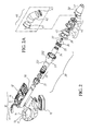
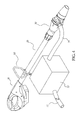
- the weeder for a pond of the present invention is used to remove by sucking weeds or dirt in water of the pond, and is composed mainly of a handle unit 10, a long pipe 20, an electric device 30, a knife/blade device 40 and a sucking mouth piece unit 50.
- the handle unit 10 is composed of a right cover part 11 and a left cover part 12 symmetrical to each other, and has an elongate hole 13 in the front end of it to receive thereon a grasp 14.
- the grasp 14 is for grasping of a hand, and is provided thereon with a switch 15 suiting manipulation of a finger; for instance, a slide switch 15 is depicted in the drawings used to control a set of power source equipment 16 provided detachably on a lower edge of the right cover part 11 and the left cover part 12.
- the switch 15 is provided above an upper edge of the grasp 14 in favor of manipulation of the finger.
- a safety device 17 is provided on an upper edge of the elongate hole 13; the switch 15 can only be operated when the safety device 17 has been operated.
- the power source equipment 16 is a chargeable battery that can safely provide D.C. electric power.
- the front end of the long pipe 20 is clamped and connected by the right cover part 11 and the left cover part 12 of the handle unit 10, and is extended outwardly.
- the electric device 30 is provided on the rear end of the long pipe 20, a pipe locking sleeve 31 is provided at the joint of the long pipe 20 with the electric device 30, the pipe locking sleeve 31 is screw connected with an electric power adapter 32 which is extended into a housing 33 for electrically connecting with a motor 34.
- the motor 34 is controlled for operation by the switch 15.
- the housing 33 is in the shape of a horn, and has a cylindrical portion 331 and a conical portion 332; the cylindrical portion 331 is slipped over the electric power adapter 32, while the conical portion 332 receives therein the motor 34.
- An opening of the conical portion 332 of the housing 33 is provided therein with an electric rack 35, a sealing pad 36, an oil seal 37 and a lid 38 for covering the opening of the conical portion 332, a rotation axle of the motor 34 is extended through these elements into the knife/blade device 40; such a structure renders the electrically conductive parts in the electric device 30 installed in a waterproof mode.
- the knife/blade device 40 is connected with the electric device 30 by means of a knife/blade housing 41.
- the knife/blade housing 41 has a front chamber 411 and a rear chamber 412 in communication with each other, the front chamber 411 is provided therein with a blade 42 and has an exhaust channel 413 to connect with a filtering tank 72 by means of a pipe line 71 extending out of its side wall (please refer to Fig. 4 ).
- the rear chamber 412 is provided therein with a rack 43 for a knife 44.
- the blade 42 and the knife 44 both are linked with the motor 34 and thus are rotated.
- the knife/blade housing 41 of the knife/blade device 40 is connected with the conical portion 332 of the housing 33 by means of an annular sealing pad 45.
- the sucking mouth piece unit 50 is communicated with the rear chamber 412 of the knife/blade housing 41 of the knife/ blade device 40 to cover the knife 44, as shown in Figs. 1-3 , the sucking mouth piece unit 50 is a pipe like hood tapered at its rear end which forms on its tailing end a sucking mouth piece 51.
- a fixing sleeve 61 is connected with the front chamber 411 of the knife/blade housing 41, the fixing sleeve 61 is slipped in an end of a bended pipe 62, the other end of the bended pipe 62 is slipped over a guarding lid 63 with a check-like surface.
- the weeder for a pond of the present invention can be connected with the pipe line 71 at the exhaust channel 413, the other end of the pipe line 71 is connected with the filtering tank 72, and an exhaust pipe 73 of the filtering tank 72 makes flowing of the water filtered back to the pond.
- the long pipe 20 preferably is mounted with a handle loop 80.
- a user when in using the present invention, a user can use his two hands to hold respectively the grasp 14 and the handle loop 80.
- Four fingers other than the thumb can be used to press the safety device 17, while the thumb can be used to trigger the switch 15, so that the motor 34 in the electric device 30 is activated to make rotation of the blade 42 and the knife 44.
- the motor 34 in the electric device 30 is activated to make rotation of the blade 42 and the knife 44.
- the present invention is installed therein with the knife 44 which can mince the sucked in weeds, leaves, branches or dirt, thereby a burden on the filtering tank 72 can be largely reduced; and water filtered through the filtering tank 72 can directly flow back to the pond P.
Landscapes
- Life Sciences & Earth Sciences (AREA)
- Marine Sciences & Fisheries (AREA)
- Environmental Sciences (AREA)
- Catching Or Destruction (AREA)
Applications Claiming Priority (1)
| Application Number | Priority Date | Filing Date | Title |
|---|---|---|---|
| US11/832,668 US7465392B1 (en) | 2007-08-02 | 2007-08-02 | Weeder for pond |
Publications (1)
| Publication Number | Publication Date |
|---|---|
| EP2039237A2 true EP2039237A2 (de) | 2009-03-25 |
Family
ID=40118674
Family Applications (1)
| Application Number | Title | Priority Date | Filing Date |
|---|---|---|---|
| EP08000314A Withdrawn EP2039237A2 (de) | 2007-08-02 | 2008-01-09 | Unkrautjäter für einen Teich |
Country Status (2)
| Country | Link |
|---|---|
| US (1) | US7465392B1 (de) |
| EP (1) | EP2039237A2 (de) |
Cited By (1)
| Publication number | Priority date | Publication date | Assignee | Title |
|---|---|---|---|---|
| CN105638069A (zh) * | 2016-01-11 | 2016-06-08 | 安徽理工大学 | 一种人体肩背式轻型挖藕机 |
Families Citing this family (6)
| Publication number | Priority date | Publication date | Assignee | Title |
|---|---|---|---|---|
| USD611665S1 (en) * | 2008-02-18 | 2010-03-09 | Hozelock Limited | Hand-held pond vacuum cleaner |
| US9194094B1 (en) * | 2012-05-31 | 2015-11-24 | Carl A. Sobel | Oil collection assembly |
| US11266068B2 (en) * | 2019-12-02 | 2022-03-08 | FYTO, Inc. | System and method for aquatic plant harvesting |
| US12477965B2 (en) * | 2021-04-30 | 2025-11-25 | Jeffrey T. Davis | Weeding device |
| KR102348032B1 (ko) * | 2021-09-10 | 2022-01-06 | 박정렬 | 어항 내 이물질 추출기 |
| US12568883B2 (en) | 2022-01-19 | 2026-03-10 | 42Farms, Llc | Method and system for computer-assisted harvesting |
Family Cites Families (12)
| Publication number | Priority date | Publication date | Assignee | Title |
|---|---|---|---|---|
| US1571395A (en) * | 1924-11-06 | 1926-02-02 | Ansel R Clark | Apparatus and method for collecting seaweed |
| US2629218A (en) * | 1948-07-27 | 1953-02-24 | John P Smith | Marine harvester with conveyer |
| US3225930A (en) * | 1963-10-09 | 1965-12-28 | Aquariums Inc | Aquarium cleaning device |
| US3546858A (en) * | 1969-02-10 | 1970-12-15 | Merle P Chaplin | Harvesting marine growths |
| US3808779A (en) * | 1972-02-17 | 1974-05-07 | Sea Harvest | Sea harvesting apparatus and method |
| US4261160A (en) * | 1979-10-15 | 1981-04-14 | Niewiera Joseph J | Weed removal apparatus |
| US4555063A (en) * | 1984-02-03 | 1985-11-26 | Glenwood Manufacturing Corporation | Liquid waste agitating and pumping apparatus |
| US5197263A (en) * | 1991-09-13 | 1993-03-30 | The Lemna Corporation | Method and apparatus for harvesting aquatic plants |
| US20030101523A1 (en) * | 2000-10-04 | 2003-06-05 | Lepley John Alden | Hot tub and spa cleaner |
| US7022223B2 (en) * | 2003-05-13 | 2006-04-04 | Tesomas Holdings Llc | Methods and systems for removing floating solid waste from the surface of a watercourse |
| CN1720792A (zh) * | 2004-07-12 | 2006-01-18 | Maw池塘技术公司 | 用于清除纤维藻或莠草的池塘清洁机的操作装置 |
| US7178188B1 (en) * | 2004-09-02 | 2007-02-20 | Richard Jaakola | Battery operated spa vacuum |
-
2007
- 2007-08-02 US US11/832,668 patent/US7465392B1/en not_active Expired - Fee Related
-
2008
- 2008-01-09 EP EP08000314A patent/EP2039237A2/de not_active Withdrawn
Cited By (2)
| Publication number | Priority date | Publication date | Assignee | Title |
|---|---|---|---|---|
| CN105638069A (zh) * | 2016-01-11 | 2016-06-08 | 安徽理工大学 | 一种人体肩背式轻型挖藕机 |
| CN105638069B (zh) * | 2016-01-11 | 2017-07-14 | 安徽理工大学 | 一种人体肩背式轻型挖藕机 |
Also Published As
| Publication number | Publication date |
|---|---|
| US7465392B1 (en) | 2008-12-16 |
Similar Documents
| Publication | Publication Date | Title |
|---|---|---|
| US7465392B1 (en) | Weeder for pond | |
| US7520015B1 (en) | Portable submersible cleaning device | |
| US7178188B1 (en) | Battery operated spa vacuum | |
| AU2018205126B2 (en) | A marine cleaning system | |
| DE10112129A1 (de) | Saugmodul | |
| EP3525645B1 (de) | Saugwerkzeug für ein flächenreinigungsgerät | |
| AU2003287407A1 (en) | Portable electric pool cleaner | |
| EP4054390B1 (de) | Nass-trocken-staubsauger | |
| EP3641612A1 (de) | Oberflächenreinigungsvorrichtung | |
| US20030101523A1 (en) | Hot tub and spa cleaner | |
| US11304411B2 (en) | Safety system for a fish-tank siphon | |
| CN110234259B (zh) | 表面清洁装置 | |
| US8342917B2 (en) | Fish scaling assembly | |
| US20080120897A1 (en) | Portable device for swatting and collecting bugs | |
| CA2453731C (en) | Blower-vacuum devices | |
| JP3204917U (ja) | 魚貝類処理装置 | |
| CN214761320U (zh) | 外科手术器械 | |
| CN211187506U (zh) | 一种腹腔镜手术用可清洗伤口的电切刀 | |
| US7140069B1 (en) | Grease extractor | |
| KR200336371Y1 (ko) | 다이아몬드 스킨 필링기 | |
| KR200293029Y1 (ko) | 숯불 로스터 | |
| KR101476163B1 (ko) | 필터조립체 및 그것을 구비한 진공청소기 | |
| KR20000065878A (ko) | 귀지자동소제장치 | |
| GB2304030A (en) | Vacuum cleaner attachment | |
| KR20210061701A (ko) | 창틀청소기 |
Legal Events
| Date | Code | Title | Description |
|---|---|---|---|
| PUAI | Public reference made under article 153(3) epc to a published international application that has entered the european phase |
Free format text: ORIGINAL CODE: 0009012 |
|
| AK | Designated contracting states |
Kind code of ref document: A2 Designated state(s): AT BE BG CH CY CZ DE DK EE ES FI FR GB GR HR HU IE IS IT LI LT LU LV MC MT NL NO PL PT RO SE SI SK TR |
|
| AX | Request for extension of the european patent |
Extension state: AL BA MK RS |
|
| 17P | Request for examination filed |
Effective date: 20090803 |
|
| STAA | Information on the status of an ep patent application or granted ep patent |
Free format text: STATUS: THE APPLICATION HAS BEEN WITHDRAWN |
|
| 18W | Application withdrawn |
Effective date: 20121029 |