EP2039264B1 - Einstellbares Selbstverriegelungshilfssystem - Google Patents
Einstellbares Selbstverriegelungshilfssystem Download PDFInfo
- Publication number
- EP2039264B1 EP2039264B1 EP08253086A EP08253086A EP2039264B1 EP 2039264 B1 EP2039264 B1 EP 2039264B1 EP 08253086 A EP08253086 A EP 08253086A EP 08253086 A EP08253086 A EP 08253086A EP 2039264 B1 EP2039264 B1 EP 2039264B1
- Authority
- EP
- European Patent Office
- Prior art keywords
- base member
- planar base
- planar
- support
- slot
- Prior art date
- Legal status (The legal status is an assumption and is not a legal conclusion. Google has not performed a legal analysis and makes no representation as to the accuracy of the status listed.)
- Not-in-force
Links
- 238000000034 method Methods 0.000 claims abstract description 6
- 238000010276 construction Methods 0.000 description 10
- 239000000463 material Substances 0.000 description 10
- 238000003860 storage Methods 0.000 description 2
- 229910001369 Brass Inorganic materials 0.000 description 1
- 229910000831 Steel Inorganic materials 0.000 description 1
- 239000000853 adhesive Substances 0.000 description 1
- 230000001070 adhesive effect Effects 0.000 description 1
- 239000010951 brass Substances 0.000 description 1
- 238000005520 cutting process Methods 0.000 description 1
- 230000007812 deficiency Effects 0.000 description 1
- 238000010586 diagram Methods 0.000 description 1
- 239000011521 glass Substances 0.000 description 1
- 238000004519 manufacturing process Methods 0.000 description 1
- 239000002184 metal Substances 0.000 description 1
- 229910052751 metal Inorganic materials 0.000 description 1
- 150000002739 metals Chemical class 0.000 description 1
- 239000004033 plastic Substances 0.000 description 1
- 229920003023 plastic Polymers 0.000 description 1
- 239000010959 steel Substances 0.000 description 1
- 239000002023 wood Substances 0.000 description 1
Images






Classifications
-
- A—HUMAN NECESSITIES
- A47—FURNITURE; DOMESTIC ARTICLES OR APPLIANCES; COFFEE MILLS; SPICE MILLS; SUCTION CLEANERS IN GENERAL
- A47B—TABLES; DESKS; OFFICE FURNITURE; CABINETS; DRAWERS; GENERAL DETAILS OF FURNITURE
- A47B57/00—Cabinets, racks or shelf units, characterised by features for adjusting shelves or partitions
- A47B57/58—Cabinets, racks or shelf units, characterised by features for adjusting shelves or partitions with means for adjusting partitions horizontally
- A47B57/583—Cabinets, racks or shelf units, characterised by features for adjusting shelves or partitions with means for adjusting partitions horizontally by sliding
- A47B57/585—Cabinets, racks or shelf units, characterised by features for adjusting shelves or partitions with means for adjusting partitions horizontally by sliding with connection means slidable in a rail
-
- A—HUMAN NECESSITIES
- A47—FURNITURE; DOMESTIC ARTICLES OR APPLIANCES; COFFEE MILLS; SPICE MILLS; SUCTION CLEANERS IN GENERAL
- A47B—TABLES; DESKS; OFFICE FURNITURE; CABINETS; DRAWERS; GENERAL DETAILS OF FURNITURE
- A47B57/00—Cabinets, racks or shelf units, characterised by features for adjusting shelves or partitions
- A47B57/06—Cabinets, racks or shelf units, characterised by features for adjusting shelves or partitions with means for adjusting the height of the shelves
- A47B57/26—Cabinets, racks or shelf units, characterised by features for adjusting shelves or partitions with means for adjusting the height of the shelves consisting of clamping means, e.g. with sliding bolts or sliding wedges
- A47B57/265—Cabinets, racks or shelf units, characterised by features for adjusting shelves or partitions with means for adjusting the height of the shelves consisting of clamping means, e.g. with sliding bolts or sliding wedges clamped in discrete positions, e.g. on tubes with grooves or holes
Definitions
- the present invention relates to an adjustable and self-locking support system wherein one or more support members are moveable on a planar member and are self-lockable in a position substantially perpendicular to the planar member.
- the system according to the invention may be used as a shelf for supporting books, CDs, cassettes, files, magazines or the like, wherein one or more support members are moveable along a planar base member and are self-lockable in a position substantially perpendicular to the base member when moved into engagement with the article to be supported so as to hold the articles in position on the base member, or alternatively may be used in an inverted configuration wherein the planar member provides a surface for supporting articles and is itself supported by the support members.
- Shelves for supporting objects such as books or the like having bookend dividers or support members located at fixed positions along the length of the shelf have long been known.
- a disadvantage of such systems lies in their inflexibility. Having dividers provided at predetermined positions does not afford an efficient use of space, particularly if articles of differing dimensions need to be supported.
- a bookshelf system with a shelf having a longitudinal slot and a moveable, lockable bookend with tenons which fit through the slot and are locked in place by pins passing through the tenons is described in FR 2841110A .
- a sideways force is applied to one side of the bookend causing the bookend to tilt from the vertical, frictional forces cause the pin to engage with the underside of the shelf so as to lock the bookend in place.
- both the books and the bookend must be tilted which is disadvantageous as books or the like are generally desirably shelved in a vertically upright manner.
- US 5,205,420 describes an adjustable, self-locking book rack with a pair of bookends slidably mounted on a base.
- the base has a longitudinal dovetail groove therein and extending along the length thereof and each bookend has a dovetail depending from its base which is received within the dovetail groove.
- This dovetail and dovetail groove arrangement provides the locking mechanism.
- the lateral pressure of the book causes the top portion of the bookend to be tilted rearwardly, moving the front portion of the bookend upwardly and the rear portion downwardly, locking the bookend to the base.
- a further disadvantage of this system is that the bookend is insertable and removable from the ends of the shelf only.
- DE-U-1 884 440 describes a system for supporting one or more articles in a base which has a longitudinal groove extending along the length thereof defined therein.
- the support member or bookend has a foot (e) with a sole (f) which can either be at right angles to the foot or in the form of a T, the sole preferably having a width which enables it to be inserted through the slot and then rotated into position.
- the sole acts as a locking element when pressed against the underside of the plane of the base.
- DE-A-1753050 discloses another solution for supporting articles.
- the present invention provides a support system for supporting one or more articles comprising:-
- the invention provides a kit for preparing a support system according to the first aspect comprising:-
- the invention also provides a method for constructing a support system according to the first aspect.
- an adjustable, self-locking shelf system which holds the articles to be supported firmly in place, at any desired position along the base of the shelf, in a substantially upright position.
- additional support members may readily be introduced at any desired position along the base of the shelf as and when required.
- the shelf system according to the invention is constructed from a small number of components and can easily and simply be assembled and disassembled.
- the shelf system may be provided in the form of a kit for assembly by the user.
- the invention provides a support system formed by inverting a shelf support system according to the first aspect such that the second planar surface of the planar base member provides a plane of support for supporting for one or more articles with the first planar surface of planar base member being supported by the support members.
- the support system according to the invention is suitable for supporting books, CDs, cassettes, files, magazines and any other such like articles which require storage. Any reference herein to books, bookshelves or bookends should be interpreted accordingly and is not intended to be limiting to books alone.
- shelf support system is not restricted for use in the horizontal plane but may also be used when oriented in the vertical plane, with the support members providing a horizontal supporting surface for displaying articles, such as ornaments or plants, for example.
- the support member providing the horizontal supporting surface may itself be provided with a longitudinally extending slot defined therein which opens onto an engaging surface into which an additional support member or members may be introduced, the support member providing the horizontal supporting surface thereby itself acting as a planar base member in a multi-shelf system.
- the system may be inverted to form a support system in which the second opposed planar surface of the planar base member defines the supporting surface for the one or more articles to be supported, the planar base member being supported at its first opposed surface by the supporting members.
- the support system functions as a table with the planar member functioning as the table top and the supporting members constituting the table legs, the distance between which can readily be adjusted as desired by means of the adjustable locking mechanism.
- Such an arrangement may conveniently find application as a raised tray for use by patients in a hospital bed, for example, with the gap between the supporting members being readily adjustable to comfortably fit around the users legs.
- the planar base member for use according to the invention comprises first and second opposed planar surfaces, an engaging surface and has a longitudinally extending slot defined therein.
- the planar base member may be any desired shape, suitably, for example, rectangular, and may be intended to be free-standing or mounted on a wall. Alternatively, the planar base member may form part of a larger storage structure such as a book case or the like.
- the planar base member may be made from any material which is conventionally used in shelving systems provided that it is sufficiently strong to bear the weight of the article or articles to be supported. Conveniently, the planar base member may be made from a plastics materials but other materials such as wood, metals or glass may also conveniently be used. If desired, the planar base member may be provided with a retaining lip along one or more of its edges. Where the planar base member constitutes the supporting surface of a table system such as a raised tray intended for use in bed, it will generally be provided with a retaining lip as discussed above and may also be provided with additional features such as cup holders, which may be integral to the planar member or may be affixed thereto, or a gripping surface to help retain objects on the supporting surface.
- cup holders which may be integral to the planar member or may be affixed thereto, or a gripping surface to help retain objects on the supporting surface.
- the longitudinally extending slot defined in the planar base member may suitably be formed using standard cutting techniques conventional in the art, the choice of which will depend on the material from which the planar base member is constructed. It will be appreciated that as the shelf system according to the present invention does not require the support member or members to be introduced or removed from the ends of the planar base member, the longitudinally extending slot need not extend along the whole of the length of the base member although in one embodiment it may do so.
- the width of the slot will be chosen such it is sufficiently wide for the locking member depending from the bottom wall of the support member to extend through the slot but is less wide than the length of the locking bar.
- the longitudinally extending slot defined in the planar base member extends through the first planar surface and opens into a longitudinally extending cavity formed within the planar base member, intermediate between the first and second opposed planar surfaces.
- the engaging surface in this embodiment is provided by the wall of the cavity proximal to the first planar surface of the planar base member.
- the longitudinally extending cavity within the planar base member comprises first and second opposed walls, said walls being substantially parallel to the first planar surface of the planar base member.
- a shelf support system according to the invention may comprise a single support member, for example, where the shelf is wall-mounted and a perpendicular wall acts as a second support member, the article or articles being supported between the support member and the wall.
- the shelf system according to the invention comprises a plurality of support members, especially two.
- the one or more supporting members may be made from any material which is conventionally used in shelving systems.
- the supporting member or members may be made from the same materials as the planar base member but the invention also contemplates the use of different materials to manufacture the planar base member and supporting member(s).
- the one or more support members may be of any desired shape, provided that this includes a surface defining a plane of support and basal wall substantially perpendicular to said support defining surface.
- the shelf system comprises a plurality of support members, these may be of the same or different shapes.
- the one or more support members are rectangular in shape.
- Each supporting member for use according to the invention has a linking member depending from the basal wall thereof.
- the basal wall is that wall of the support member which is supported on the top or uppermost surface of the planar base member in the assembled construction.
- the linking member depends from the mid point of the basal wall of the support member.
- the linking member may be attached at one end to the support member by any conventional attaching means such as by adhesive or using screws or nuts and bolts or, in one embodiment, one end of the linking member may be inserted into the basal wall of the support member.
- a support member in which the depending linking member is formed integrally with the support member is also envisaged according to the invention.
- the linking member may suitably be prepared from any material provided that it is sufficiently strong to lockingly engage the support member to the planar base member in operation.
- the linking member is made from materials such as steel or brass or other such similarly strong materials.
- the linking member comprises a substantially L-shaped stem and has a locking bar located at the end of the stem distal to the bottom wall of the support member and arranged perpendicularly to the stem.
- the locking bar may suitably comprise one shoulder arranged perpendicularly to the end of the stem or more preferably comprises two shoulders arranged equally on either side, and perpendicularly, to the end of the stem.
- the linking member, support member and/or planar base member may additionally comprise means, such as pins, slots or serrations, to increase the frictional engagement between the base member and support member(s) in the locked position. This is of particular importance when the support member is to be deployed in a horizontal position.
- the linking member extends through the slot in the planar base member and the L-shaped configuration of the stem and the perpendicular arrangement of the locking bar around this end of the stem ensures that when the support member is positioned perpendicularly to the planar base member, the locking bar is brought into engagement with the engaging surfaceof the planar base member.
- the length of the locking bar is greater than the width of the slot in the planar base member, the locking bar cannot pass back through the slot when the support member is rotated into position but instead is forced into engagement with the engaging surface of the planar base member thereby locking the support member in position. Tilting the support member away from the perpendicular allows the position of the support member to be adjusted as it causes the locking bar to become disengaged from the planar base member, thereby allowing the support member to slide longitudinally along the top wall of the planar base member.
- the process of attaching a support member to the planar base member is straightforward and comprises the steps of, first, laying the support member on the first planar surface of the planar base member, with the basal wall of the support member aligned with the slot in the planar base member, thenpushing the locking bar through the slot, rotating the support member through 90° and finally raising the support to an position where it is perpendicular to the planar base member.
- the arm of the L-shaped linking member to which the locking bar is attached must be sufficiently long to allow the locking bar to pass beyond the distal opening of the slot when the support member lies flat on the planar base member.
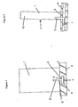
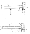
- FIG. 1 this shows a support member (1), the basal wall (2) of which is supported on the first, top surface (3) of the planar base member (4).
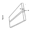
- the construction of the planar base member can be seen in Figure 6 .
- a linking member (5) is shown inserted into the basal wall of the support member and extending through the slot (6) in the planar base member beyond the distal opening of the slot.
- a locking bar (7) which in the embodiment shown comprises two shoulders arranged equally on either side and perpendicularly to the end of the stem of the linking element, is located in a longitudinally extending cavity (8) formed within the planar base member, intermediate between the first and second opposed planar surfaces.
- the engaging surface (9) is provided by the wall of the cavity proximal to the first planar surface of the planar base member (4). The support member in the upright position as shown, engages this engaging surface.
- Figure 2 shows a side view of this arrangement.
- the locking bar (7) of the linking member (5) is urged into locking engagement with the wall of the cavity proximal to the first planar surface of the planar base member (4).
- Figure 9 shows an alternative embodiment wherein the locking bar (5) of the linking member (7) interacts with a serration (shown as (12) in Figure 11 ) provided in the wall to provide increased frictional engagement.
- FIG. 6 shows an alternative planar base member suitable for use according to the invention in which the slot does not extend along the whole length of the base member.
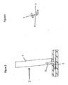
- Figure 3 illustrates how tilting the support member away from the perpendicular disengages the locking bar from the engaging surface of the planar support member.
- the direction in which the support member must be rotated in order to move it to the perpendicular, locked position is indicated by the arrow Z.
- the corresponding arrangement for the embodiment of Figure 9 is shown in Figure 10 .
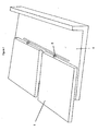
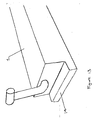
- the support member(1) is laid on the first planar surface of the planar base member (4), with the basal wall of the support member aligned with the slot in the planar base member and the locking bar of the linking member (5) is pushed through the slot, as shown in Figure 7 .
- the construction of the linking member can be seen in Figure 4 .
- the linking member comprises an L-shaped stem and a locking bar (7) and the arm of the L-shaped linking member (11) to which the locking bar is attached is sufficiently long to allow the locking bar to pass beyond the distal opening of the slot when the support member lies flat on the planar base member.
- the length of the locking bar is greater than the width of the slot in the planar base member.
- the support member is rotated through 90° , still lying on the planar base member (as shown in Figure 8 ), and finally the support member is raised to a position where it is perpendicular to the planar base member. In this position, the locking bar is brought into engagement with the engaging surface of the planar base member. As the length of the locking bar is greater than the width of the slot in the planar base member, the locking bar cannot pass back through the slot when the support member is rotated into position but instead is forced into engagement with the engaging surface of the planar base member thereby locking the support member in position.
- FIG. 9 to 14 Embodiments of the arrangements described above in which the planar base member and/or support members are provided with means to increase the frictional engagement between the planar base member and support member are shown in Figures 9 to 14 .
- Figures 9 to 11 show an embodiment in which the planar base member comprises serrations (12) with which the locking bar of the linking member interacts in the locked position.
- Figure 12 shows a planar base member (4) provided with a slot (13) into which can be inserted a pin or slot (14) extending from the basal wall of the support member (1) (as shown in Figure 13 ) to lock the support member in position.
- the assembled construction is shown in Figure 14 .
- Figure 15 shows an inserted construction in which the planar base member (4)forms a table top which is supported on its underneath by support members (1).
Landscapes
- Assembled Shelves (AREA)
- Display Racks (AREA)
- Supports Or Holders For Household Use (AREA)
Claims (10)
- System zum Stützen eines Gegenstands oder mehrerer Gegenstände, Folgendes umfassend:ein planes Basisteil (4) mit einer ersten (3) und zweiten entgegengesetzten planen Fläche und einer Eingriffsfläche (9), wobei das plane Basisteil einen sich längs erstreckenden, darin ausgebildeten Schlitz (6) aufweist, der sich durch die erste plane Fläche (3) des Basisteils (4) erstreckt und in einen sich längs erstreckenden Hohlraum mündet, der im planen Basisteil gebildet ist;
undein oder mehrere Stützteil/e (1), wobei jedes Stützteil eine Fläche umfasst, die eine Stützebene (10) für den einen Gegenstand oder die mehreren Gegenstände bildet,eine zu der die Stütze bildenden Fläche im Wesentlichen senkrechte Basiswand (2), wobei die Wand mit der ersten planen Fläche (3) des planen Basisteils (4) in Kontakt ist, undein Verbindungsteil (5), das von der Basiswand des Stützteils abhängt und sich durch den Schlitz (6) im planen Basisteil erstreckt,wobei das Verbindungsteil (5) einen im Wesentlichen L-förmigen Schaft umfasst und einen Arretierungsriegel (7) mit einer Länge aufweist, die größer ist als die Breite des Schlitzes (6), um die Eingriffsfläche (9) des planen Basisteils in Eingriff zu halten,dadurch gekennzeichnet, dassdie Eingriffsfläche (9) durch die zur ersten planen Fläche (3) des planen Basisteils proximale Wand des Hohlraums bereitgestellt wird; undsich der Arretierungsriegel (7) am Ende des Schenkels des L-förmigen Schafts distal zur Basiswand des Stützteils (1) befindet und im Wesentlich senkrecht dazu angeordnet ist, wobei die Länge des Schenkels des L-förmigen Schafts proximal zur Basiswand in Bezug auf die Tiefe des Schlitzes dergestalt ist, dass der Arretierungsriegel die Eingriffsfläche des planen Basisteils in Eingriff hält, wenn das Stützteil im Wesentlichen senkrecht zum planen Basisteil ist, und die Länge des Schenkels des L-förmigen Schafts (11) distal zur Basiswand in Bezug auf die Tiefe des Schlitzes dergestalt ist, dass, wenn während des Zusammenbaus das Stützteil (1) flach auf der ersten planen Fläche (3) des planen Basisteils (4) liegt, wobei die Basiswand (2), von der das Verbindungsteil abhängt, mit dem Schlitz ausgerichtet ist, sich der Arretierungsriegel über die distale Öffnung des Schlitzes hinaus erstreckt. - System nach Anspruch 1, wobei die entgegengesetzten Wände des sich längs erstreckenden Hohlraums im Wesentlichen parallel zur ersten planen Fläche (3) des planen Basisteils sind.
- System nach Anspruch 1 oder Anspruch 2, mehrere Stützteile (1) umfassend.
- System nach jedem vorhergehenden Anspruch, wobei das Verbindungsteil (5) vom Mittelpunkt der Basiswand (2) des Stützteils abhängt.
- System nach jedem vorhergehenden Anspruch, wobei der Arretierungsriegel (7) zwei Schultern umfasst, die auf jeder Seite gleich und senkrecht zum Ende des Schafts des Verbindungsteils angeordnet sind.
- System nach jedem vorhergehenden Anspruch, wobei das Verbindungsteil (5) zusätzlich Einrichtungen umfasst, um den Reibschluss mit dem Basisteil in der arretierten Stellung zu verstärken.
- System nach Anspruch 6, wobei die Einrichtungen zum Verstärken des Reibschlusses mit dem Basisteil in der arretierten Stellung Stifte oder Kerbverzahnungen (12) umfassen.
- System nach Anspruch 1, das umgekehrt ist, um ein Stützsystem zu bilden, bei dem die zweite entgegengesetzte plane Fläche des planen Basisteils die Stützfläche für den einen zu stützenden Gegenstand oder die mehreren zu stützenden Gegenstände bildet, wobei das plane Basisteil an seiner ersten entgegengesetzten Fläche durch die Stützteile gestützt ist.
- Bausatz zum Herstellen eines Stützsystems nach Anspruch 1, Folgendes umfassend:ein planes Basisteil (4) mit einer ersten (3) und zweiten entgegengesetzten planen Fläche und einer Eingriffsfläche (9), wobei das plane Basisteil einen sich längs erstreckenden, darin ausgebildeten Schlitz (6) aufweist, der sich durch die erste plane Fläche (3) des Basisteils (4) erstreckt und in einen sich längs erstreckenden Hohlraum mündet, der im planen Basisteil gebildet ist; wobei die Eingriffsfläche (9) durch die zur ersten planen Fläche (3) des planen Basisteils proximale Wand des Hohlraums bereitgestellt wird;
undein oder mehrere Stützteil/e (1), wovon jedes eine Fläche umfasst, die eine Stützebene (10) und eine Basiswand (2) im Wesentlichen senkrecht zu der die Stütze bildenden Fläche mit einem von dieser abhängenden Verbindungsteil (5) umfasst,wobei das Verbindungsteil einen im Wesentlichen L-förmigen Schaft umfasst und einen Arretierungsriegel (7) mit einer Länge aufweist, die größer ist als die Breite des Schlitzes, der im Wesentlichen senkrecht zum Schaft angeordnet ist und sich am Ende des Schenkels des L-förmigen Schafts (11) distal zur Basiswand des Stützteils befindet, wobei die Länge des Schenkels des L-förmigen Schafts proximal zur Basiswand in Bezug auf die Tiefe des Schlitzes dergestalt ist, dass der Arretierungsriegel die Eingriffsfläche des planen Basisteils in Eingriff hält, wenn das Stützteil im Wesentlichen senkrecht zum planen Basisteil ist, und die Länge des Schenkels des L-förmigen Schafts (11) distal zur Basiswand in Bezug auf die Tiefe des Schlitzes dergestalt ist, dass,wenn während des Zusammenbaus das Stützteil (1) flach auf der ersten planen Fläche (3) des planen Basisteils (4) liegt, wobei die Basiswand (2), von der das Verbindungsteil abhängt, mit dem Schlitz ausgerichtet ist, sich der Arretierungsriegel über die distale Öffnung des Schlitzes hinaus erstreckt. - Verfahren zum Aufbauen eines Stützsystems nach einem der Ansprüche 1 bis 8, die folgenden Schritte umfassend:(i) das eine oder die mehreren Stützteil/e (1) auf die erste plane Fläche (3) des planen Basisteils (4) zu legen, wobei die Basiswand jedes Stützteils mit dem Schlitz im planen Basisteil ausgerichtet ist;(ii) den Arretierungsriegel des Arretierungsteils jedes Stützteils durch den Schlitz einzustecken;(iii) jedes Stützteil um 90° zu drehen, während es immer noch auf dem planen Basisteil aufliegt; und(iv) jedes Stützteil in eine Stellung anzuheben, in der es im Wesentlichen senkrecht zum planen Basisteil ist.
Applications Claiming Priority (3)
| Application Number | Priority Date | Filing Date | Title |
|---|---|---|---|
| GB0718454A GB0718454D0 (en) | 2007-09-21 | 2007-09-21 | Adjustable self-locking shelf system |
| GB0804287A GB0804287D0 (en) | 2008-03-07 | 2008-03-07 | Adjustable self-locking shelf system |
| GB0805710A GB0805710D0 (en) | 2008-03-29 | 2008-03-29 | Adjustable self-locking support system |
Publications (2)
| Publication Number | Publication Date |
|---|---|
| EP2039264A1 EP2039264A1 (de) | 2009-03-25 |
| EP2039264B1 true EP2039264B1 (de) | 2012-04-11 |
Family
ID=40084158
Family Applications (1)
| Application Number | Title | Priority Date | Filing Date |
|---|---|---|---|
| EP08253086A Not-in-force EP2039264B1 (de) | 2007-09-21 | 2008-09-19 | Einstellbares Selbstverriegelungshilfssystem |
Country Status (2)
| Country | Link |
|---|---|
| EP (1) | EP2039264B1 (de) |
| AT (1) | ATE552751T1 (de) |
Families Citing this family (1)
| Publication number | Priority date | Publication date | Assignee | Title |
|---|---|---|---|---|
| CN109928192B (zh) * | 2019-03-30 | 2024-04-19 | 深圳市亚的斯自动化设备有限公司 | 一种贴片机供料器安装座间距调节机构 |
Citations (1)
| Publication number | Priority date | Publication date | Assignee | Title |
|---|---|---|---|---|
| DE1753050A1 (de) * | 1968-01-29 | 1971-07-08 | Hanning Kunststoffe R | Einrichtung zum verstellbaren Aufhaengen von Zwischenboeden,Regalbrettern oder aehnlichen Bauelementen an senkrechtstehenden Moebelteilen |
Family Cites Families (6)
| Publication number | Priority date | Publication date | Assignee | Title |
|---|---|---|---|---|
| US1898533A (en) * | 1931-03-12 | 1933-02-21 | Stanley R Harriman | Paper file |
| FR1345648A (fr) * | 1962-10-18 | 1963-12-13 | Serre-livres amovible | |
| GB1401220A (en) * | 1972-12-04 | 1975-07-16 | Sales Achievement | Shelving |
| US5205420A (en) | 1992-04-20 | 1993-04-27 | Joseph Petryszak | Adjustable and self-locking book rack or book support |
| FR2841110B1 (fr) | 2002-06-21 | 2005-04-22 | Daniel Willy Robert Berenbaum | Ensemble etagere appui-livres |
| GB2381736B (en) * | 2002-08-23 | 2003-09-24 | William Stenard Landale | Movable cantilever support |
-
2008
- 2008-09-19 EP EP08253086A patent/EP2039264B1/de not_active Not-in-force
- 2008-09-19 AT AT08253086T patent/ATE552751T1/de active
Patent Citations (1)
| Publication number | Priority date | Publication date | Assignee | Title |
|---|---|---|---|---|
| DE1753050A1 (de) * | 1968-01-29 | 1971-07-08 | Hanning Kunststoffe R | Einrichtung zum verstellbaren Aufhaengen von Zwischenboeden,Regalbrettern oder aehnlichen Bauelementen an senkrechtstehenden Moebelteilen |
Also Published As
| Publication number | Publication date |
|---|---|
| ATE552751T1 (de) | 2012-04-15 |
| EP2039264A1 (de) | 2009-03-25 |
Similar Documents
| Publication | Publication Date | Title |
|---|---|---|
| US11064817B2 (en) | Merchandiser and methods relating to same | |
| US8607997B2 (en) | Modular merchandise display system | |
| US20180035825A1 (en) | Adjustable grid mount and related methods | |
| EP3849381A1 (de) | Speicherkomponenten für ein konfigurierbares speichersystem | |
| US20140021844A1 (en) | Under cabinet drawer assembly | |
| JP2014531947A (ja) | 道具、特に工具の収納用デバイス | |
| US20220338627A1 (en) | Extendable Storage Component for a Storage System | |
| US5205420A (en) | Adjustable and self-locking book rack or book support | |
| US5740926A (en) | Bookshelf with adjustable locking bookends | |
| TW201210546A (en) | Merchandise display system | |
| WO2005112696A3 (en) | Spice rack | |
| JPS63305810A (ja) | 用具キャビネット | |
| US20240349922A1 (en) | Knife block and knife storage system | |
| US3142384A (en) | Adjustable book shelves and book ends | |
| EP2039264A1 (de) | Einstellbares Selbstverriegelungshilfssystem | |
| JP3135217U (ja) | 書棚及びそれに用いる棚板係止具 | |
| US20080023427A1 (en) | Modular shelf system | |
| JP2019076311A (ja) | 棚装置及び天板付き什器 | |
| JP6784506B2 (ja) | 組み合わせ家具 | |
| JP3255295U (ja) | 本立て、収納装置 | |
| KR200411326Y1 (ko) | 가변 책상판을 가진 책상장 | |
| JP2534192Y2 (ja) | 引出し付き本立 | |
| KR200256073Y1 (ko) | 책장이 부착된 책상 | |
| KR20110000759U (ko) | 가구용 디바이더 | |
| US20060157429A1 (en) | Media storage organizer and method for using same |
Legal Events
| Date | Code | Title | Description |
|---|---|---|---|
| PUAI | Public reference made under article 153(3) epc to a published international application that has entered the european phase |
Free format text: ORIGINAL CODE: 0009012 |
|
| 17P | Request for examination filed |
Effective date: 20081004 |
|
| AK | Designated contracting states |
Kind code of ref document: A1 Designated state(s): AT BE BG CH CY CZ DE DK EE ES FI FR GB GR HR HU IE IS IT LI LT LU LV MC MT NL NO PL PT RO SE SI SK TR |
|
| AX | Request for extension of the european patent |
Extension state: AL BA MK RS |
|
| 17Q | First examination report despatched |
Effective date: 20090526 |
|
| RAP1 | Party data changed (applicant data changed or rights of an application transferred) |
Owner name: HELPS, JIM |
|
| RIN1 | Information on inventor provided before grant (corrected) |
Inventor name: HELPS, JIM |
|
| AKX | Designation fees paid |
Designated state(s): AT BE BG CH CY CZ DE DK EE ES FI FR GB GR HR HU IE IS IT LI LT LU LV MC MT NL NO PL PT RO SE SI SK TR |
|
| GRAP | Despatch of communication of intention to grant a patent |
Free format text: ORIGINAL CODE: EPIDOSNIGR1 |
|
| GRAS | Grant fee paid |
Free format text: ORIGINAL CODE: EPIDOSNIGR3 |
|
| GRAA | (expected) grant |
Free format text: ORIGINAL CODE: 0009210 |
|
| AK | Designated contracting states |
Kind code of ref document: B1 Designated state(s): AT BE BG CH CY CZ DE DK EE ES FI FR GB GR HR HU IE IS IT LI LT LU LV MC MT NL NO PL PT RO SE SI SK TR |
|
| REG | Reference to a national code |
Ref country code: GB Ref legal event code: FG4D |
|
| REG | Reference to a national code |
Ref country code: CH Ref legal event code: EP |
|
| REG | Reference to a national code |
Ref country code: AT Ref legal event code: REF Ref document number: 552751 Country of ref document: AT Kind code of ref document: T Effective date: 20120415 |
|
| REG | Reference to a national code |
Ref country code: IE Ref legal event code: FG4D |
|
| REG | Reference to a national code |
Ref country code: DE Ref legal event code: R096 Ref document number: 602008014777 Country of ref document: DE Effective date: 20120606 |
|
| REG | Reference to a national code |
Ref country code: NL Ref legal event code: VDEP Effective date: 20120411 |
|
| REG | Reference to a national code |
Ref country code: AT Ref legal event code: MK05 Ref document number: 552751 Country of ref document: AT Kind code of ref document: T Effective date: 20120411 |
|
| LTIE | Lt: invalidation of european patent or patent extension |
Effective date: 20120411 |
|
| PG25 | Lapsed in a contracting state [announced via postgrant information from national office to epo] |
Ref country code: IS Free format text: LAPSE BECAUSE OF FAILURE TO SUBMIT A TRANSLATION OF THE DESCRIPTION OR TO PAY THE FEE WITHIN THE PRESCRIBED TIME-LIMIT Effective date: 20120811 Ref country code: NO Free format text: LAPSE BECAUSE OF FAILURE TO SUBMIT A TRANSLATION OF THE DESCRIPTION OR TO PAY THE FEE WITHIN THE PRESCRIBED TIME-LIMIT Effective date: 20120711 Ref country code: CY Free format text: LAPSE BECAUSE OF FAILURE TO SUBMIT A TRANSLATION OF THE DESCRIPTION OR TO PAY THE FEE WITHIN THE PRESCRIBED TIME-LIMIT Effective date: 20120411 Ref country code: LT Free format text: LAPSE BECAUSE OF FAILURE TO SUBMIT A TRANSLATION OF THE DESCRIPTION OR TO PAY THE FEE WITHIN THE PRESCRIBED TIME-LIMIT Effective date: 20120411 Ref country code: SE Free format text: LAPSE BECAUSE OF FAILURE TO SUBMIT A TRANSLATION OF THE DESCRIPTION OR TO PAY THE FEE WITHIN THE PRESCRIBED TIME-LIMIT Effective date: 20120411 Ref country code: FI Free format text: LAPSE BECAUSE OF FAILURE TO SUBMIT A TRANSLATION OF THE DESCRIPTION OR TO PAY THE FEE WITHIN THE PRESCRIBED TIME-LIMIT Effective date: 20120411 Ref country code: PL Free format text: LAPSE BECAUSE OF FAILURE TO SUBMIT A TRANSLATION OF THE DESCRIPTION OR TO PAY THE FEE WITHIN THE PRESCRIBED TIME-LIMIT Effective date: 20120411 |
|
| PG25 | Lapsed in a contracting state [announced via postgrant information from national office to epo] |
Ref country code: SI Free format text: LAPSE BECAUSE OF FAILURE TO SUBMIT A TRANSLATION OF THE DESCRIPTION OR TO PAY THE FEE WITHIN THE PRESCRIBED TIME-LIMIT Effective date: 20120411 Ref country code: GR Free format text: LAPSE BECAUSE OF FAILURE TO SUBMIT A TRANSLATION OF THE DESCRIPTION OR TO PAY THE FEE WITHIN THE PRESCRIBED TIME-LIMIT Effective date: 20120712 Ref country code: LV Free format text: LAPSE BECAUSE OF FAILURE TO SUBMIT A TRANSLATION OF THE DESCRIPTION OR TO PAY THE FEE WITHIN THE PRESCRIBED TIME-LIMIT Effective date: 20120411 Ref country code: HR Free format text: LAPSE BECAUSE OF FAILURE TO SUBMIT A TRANSLATION OF THE DESCRIPTION OR TO PAY THE FEE WITHIN THE PRESCRIBED TIME-LIMIT Effective date: 20120411 Ref country code: PT Free format text: LAPSE BECAUSE OF FAILURE TO SUBMIT A TRANSLATION OF THE DESCRIPTION OR TO PAY THE FEE WITHIN THE PRESCRIBED TIME-LIMIT Effective date: 20120813 |
|
| PG25 | Lapsed in a contracting state [announced via postgrant information from national office to epo] |
Ref country code: BE Free format text: LAPSE BECAUSE OF FAILURE TO SUBMIT A TRANSLATION OF THE DESCRIPTION OR TO PAY THE FEE WITHIN THE PRESCRIBED TIME-LIMIT Effective date: 20120411 |
|
| PGFP | Annual fee paid to national office [announced via postgrant information from national office to epo] |
Ref country code: DE Payment date: 20120921 Year of fee payment: 5 |
|
| PG25 | Lapsed in a contracting state [announced via postgrant information from national office to epo] |
Ref country code: SK Free format text: LAPSE BECAUSE OF FAILURE TO SUBMIT A TRANSLATION OF THE DESCRIPTION OR TO PAY THE FEE WITHIN THE PRESCRIBED TIME-LIMIT Effective date: 20120411 Ref country code: RO Free format text: LAPSE BECAUSE OF FAILURE TO SUBMIT A TRANSLATION OF THE DESCRIPTION OR TO PAY THE FEE WITHIN THE PRESCRIBED TIME-LIMIT Effective date: 20120411 Ref country code: DK Free format text: LAPSE BECAUSE OF FAILURE TO SUBMIT A TRANSLATION OF THE DESCRIPTION OR TO PAY THE FEE WITHIN THE PRESCRIBED TIME-LIMIT Effective date: 20120411 Ref country code: EE Free format text: LAPSE BECAUSE OF FAILURE TO SUBMIT A TRANSLATION OF THE DESCRIPTION OR TO PAY THE FEE WITHIN THE PRESCRIBED TIME-LIMIT Effective date: 20120411 Ref country code: AT Free format text: LAPSE BECAUSE OF FAILURE TO SUBMIT A TRANSLATION OF THE DESCRIPTION OR TO PAY THE FEE WITHIN THE PRESCRIBED TIME-LIMIT Effective date: 20120411 Ref country code: NL Free format text: LAPSE BECAUSE OF FAILURE TO SUBMIT A TRANSLATION OF THE DESCRIPTION OR TO PAY THE FEE WITHIN THE PRESCRIBED TIME-LIMIT Effective date: 20120411 Ref country code: CZ Free format text: LAPSE BECAUSE OF FAILURE TO SUBMIT A TRANSLATION OF THE DESCRIPTION OR TO PAY THE FEE WITHIN THE PRESCRIBED TIME-LIMIT Effective date: 20120411 |
|
| PGFP | Annual fee paid to national office [announced via postgrant information from national office to epo] |
Ref country code: IE Payment date: 20121122 Year of fee payment: 5 Ref country code: FR Payment date: 20121010 Year of fee payment: 5 |
|
| PLBE | No opposition filed within time limit |
Free format text: ORIGINAL CODE: 0009261 |
|
| STAA | Information on the status of an ep patent application or granted ep patent |
Free format text: STATUS: NO OPPOSITION FILED WITHIN TIME LIMIT |
|
| PG25 | Lapsed in a contracting state [announced via postgrant information from national office to epo] |
Ref country code: IT Free format text: LAPSE BECAUSE OF FAILURE TO SUBMIT A TRANSLATION OF THE DESCRIPTION OR TO PAY THE FEE WITHIN THE PRESCRIBED TIME-LIMIT Effective date: 20120411 |
|
| 26N | No opposition filed |
Effective date: 20130114 |
|
| PG25 | Lapsed in a contracting state [announced via postgrant information from national office to epo] |
Ref country code: MC Free format text: LAPSE BECAUSE OF NON-PAYMENT OF DUE FEES Effective date: 20120930 Ref country code: ES Free format text: LAPSE BECAUSE OF FAILURE TO SUBMIT A TRANSLATION OF THE DESCRIPTION OR TO PAY THE FEE WITHIN THE PRESCRIBED TIME-LIMIT Effective date: 20120722 |
|
| REG | Reference to a national code |
Ref country code: CH Ref legal event code: PL |
|
| REG | Reference to a national code |
Ref country code: DE Ref legal event code: R097 Ref document number: 602008014777 Country of ref document: DE Effective date: 20130114 |
|
| PG25 | Lapsed in a contracting state [announced via postgrant information from national office to epo] |
Ref country code: LI Free format text: LAPSE BECAUSE OF NON-PAYMENT OF DUE FEES Effective date: 20120930 Ref country code: BG Free format text: LAPSE BECAUSE OF FAILURE TO SUBMIT A TRANSLATION OF THE DESCRIPTION OR TO PAY THE FEE WITHIN THE PRESCRIBED TIME-LIMIT Effective date: 20120711 Ref country code: CH Free format text: LAPSE BECAUSE OF NON-PAYMENT OF DUE FEES Effective date: 20120930 |
|
| PG25 | Lapsed in a contracting state [announced via postgrant information from national office to epo] |
Ref country code: MT Free format text: LAPSE BECAUSE OF FAILURE TO SUBMIT A TRANSLATION OF THE DESCRIPTION OR TO PAY THE FEE WITHIN THE PRESCRIBED TIME-LIMIT Effective date: 20120411 |
|
| PG25 | Lapsed in a contracting state [announced via postgrant information from national office to epo] |
Ref country code: TR Free format text: LAPSE BECAUSE OF FAILURE TO SUBMIT A TRANSLATION OF THE DESCRIPTION OR TO PAY THE FEE WITHIN THE PRESCRIBED TIME-LIMIT Effective date: 20120411 |
|
| PG25 | Lapsed in a contracting state [announced via postgrant information from national office to epo] |
Ref country code: LU Free format text: LAPSE BECAUSE OF NON-PAYMENT OF DUE FEES Effective date: 20120919 |
|
| REG | Reference to a national code |
Ref country code: DE Ref legal event code: R119 Ref document number: 602008014777 Country of ref document: DE Effective date: 20140401 |
|
| REG | Reference to a national code |
Ref country code: FR Ref legal event code: ST Effective date: 20140530 |
|
| REG | Reference to a national code |
Ref country code: IE Ref legal event code: MM4A |
|
| PG25 | Lapsed in a contracting state [announced via postgrant information from national office to epo] |
Ref country code: HU Free format text: LAPSE BECAUSE OF FAILURE TO SUBMIT A TRANSLATION OF THE DESCRIPTION OR TO PAY THE FEE WITHIN THE PRESCRIBED TIME-LIMIT Effective date: 20080919 Ref country code: IE Free format text: LAPSE BECAUSE OF NON-PAYMENT OF DUE FEES Effective date: 20130919 |
|
| PG25 | Lapsed in a contracting state [announced via postgrant information from national office to epo] |
Ref country code: DE Free format text: LAPSE BECAUSE OF NON-PAYMENT OF DUE FEES Effective date: 20140401 Ref country code: FR Free format text: LAPSE BECAUSE OF NON-PAYMENT OF DUE FEES Effective date: 20130930 |
|
| PGFP | Annual fee paid to national office [announced via postgrant information from national office to epo] |
Ref country code: GB Payment date: 20160920 Year of fee payment: 9 |
|
| GBPC | Gb: european patent ceased through non-payment of renewal fee |
Effective date: 20170919 |
|
| PG25 | Lapsed in a contracting state [announced via postgrant information from national office to epo] |
Ref country code: GB Free format text: LAPSE BECAUSE OF NON-PAYMENT OF DUE FEES Effective date: 20170919 |