EP2039265A1 - Structure de chaise inclinable - Google Patents
Structure de chaise inclinable Download PDFInfo
- Publication number
- EP2039265A1 EP2039265A1 EP07768133A EP07768133A EP2039265A1 EP 2039265 A1 EP2039265 A1 EP 2039265A1 EP 07768133 A EP07768133 A EP 07768133A EP 07768133 A EP07768133 A EP 07768133A EP 2039265 A1 EP2039265 A1 EP 2039265A1
- Authority
- EP
- European Patent Office
- Prior art keywords
- cushion portion
- backrest cushion
- reclining
- bell crank
- backrest
- Prior art date
- Legal status (The legal status is an assumption and is not a legal conclusion. Google has not performed a legal analysis and makes no representation as to the accuracy of the status listed.)
- Withdrawn
Links
Images


Classifications
-
- A—HUMAN NECESSITIES
- A47—FURNITURE; DOMESTIC ARTICLES OR APPLIANCES; COFFEE MILLS; SPICE MILLS; SUCTION CLEANERS IN GENERAL
- A47C—CHAIRS; SOFAS; BEDS
- A47C1/00—Chairs adapted for special purposes
- A47C1/02—Reclining or easy chairs
- A47C1/031—Reclining or easy chairs having coupled concurrently adjustable supporting parts
- A47C1/032—Reclining or easy chairs having coupled concurrently adjustable supporting parts the parts being movably-coupled seat and back-rest
- A47C1/03205—Reclining or easy chairs having coupled concurrently adjustable supporting parts the parts being movably-coupled seat and back-rest having adjustable and lockable inclination
- A47C1/0325—Reclining or easy chairs having coupled concurrently adjustable supporting parts the parts being movably-coupled seat and back-rest having adjustable and lockable inclination by means of clamps or friction locking members
-
- A—HUMAN NECESSITIES
- A47—FURNITURE; DOMESTIC ARTICLES OR APPLIANCES; COFFEE MILLS; SPICE MILLS; SUCTION CLEANERS IN GENERAL
- A47C—CHAIRS; SOFAS; BEDS
- A47C1/00—Chairs adapted for special purposes
- A47C1/02—Reclining or easy chairs
- A47C1/031—Reclining or easy chairs having coupled concurrently adjustable supporting parts
- A47C1/032—Reclining or easy chairs having coupled concurrently adjustable supporting parts the parts being movably-coupled seat and back-rest
- A47C1/03294—Reclining or easy chairs having coupled concurrently adjustable supporting parts the parts being movably-coupled seat and back-rest slidingly movable in the base frame, e.g. by rollers
Definitions
- the present invention relates to an improvement on a reclining seat structure, in more details, pertaining to such structure as being easy to recline without displacing a reclining portion (or backrest cushion portion) of the seat with regard to the back of a user thereon and with his/her body snugly fitted therein when such reclining portion tilts back and being highly endurable so that it can provide a very comfortable and favorable seat in use.
- the reclining and seating portions of the seat correspond to a backrest cushion portion hereof and a seat cushion portion hereof, respectively.
- Such reclining mechanism is generally known in the field of seating instruments such as sofas and so forth as allowing the users to take a posture of making them feel comfortable by adjusting an inclining angle of the reclining portion as they like.
- FIG 14 (a) A seating instrument adopting such conventionally known reclining mechanism is shown in Figure 14 (a) , which is arranged such that a rear lower surface of the seating portion is pivotally connected to a lower back surface of a reclining portion.
- Figure 14 (b) when the reclining portion is listed as shown in Figure 14 (b) , there arises a large gap I between a lower side surface of the reclining portion and a rear surface of the seating portion, which gap I causes the back of a user thereon to be displaced with regard to the reclining portion, with the result that the backside of a jacket is pulled up so that it wrinkles to the disadvantage of the users.
- the dislocation of the reclining portion also causes a lumbar support and a headrest disposed thereon to shift upwards accordingly so that the users cannot help shifting themselves to a position where they feel comfortable, to their inconveniences.
- the pivotal fulcrum of the reclining portion with regard to the basic frame is arranged on an upper part of such portion so that the listing back of such portion causes the seating portion to push out forwards from the frame, in which an ottoman or footstool disposed in front of the seating portion shall be pulled back towards the users when the seating portion is pulled back by raising the reclining portion, to their extreme inconveniences.
- the present invention is to provide a reclining seat structure that prevents the back of a user from being displaced from a reclining portion thereof even though such user lists back the reclining portion and is easy to take a reclining position of making such user feel very comfortable, and is effective for saving a space for disposition and convenient to use as well as being highly endurable.
- the present invention is characterized in comprising a seat cushion portion 1 whose bottom portion is supported by a seating frame 11; a backrest cushion portion 2 whose backside surface is supported by a back frame 21; a base 3, on a rear side of which a raised support portion 31 is provided and on which the cushion portions 1 and 2 are movably supported; and a bell crank 4 that is connected slidably in a vertical direction on the back frame 21 and an intermediate link portion 41 of which crank is swingably supported around the raised support portion 31, wherein an upper backside surface of the seat cushion portion 1 and a bottom side frontal surface of the backrest cushion portion 2 are foldabley connected so as to form a connection portion C, around which portion the backrest cushion portion 2 as a whole reclines on the base 3, and a rear end portion 11a of the seating frame 11 and a lower end portion 42 of the bell crank 4 are pivotally connected and the seat cushion portion 1 is to and fro movable integrally with the seating frame 11 on the base 3, wherein upon the seat cushion portion 1 sliding forwards
- the present invention is characterized in providing a supporting plate 43, which abuts on the backside surface of the backrest cushion portion 2, above the link portion 41.
- the present invention is characterized in slidably connecting the back frame 21 with the bell crank 4 by disposing bosses R on the back frame 21 and inserting those bosses in respective guide channels 44 arranged on the upper part of the bell crank 4.
- the present invention is characterized in fixing the backrest cushion potion 2 with a tilting angle as required by providing a stopper 5 in which a positioning rod 51 is engaged on a beam 11b disposed at the frontal end of the seating frame 11 and the rod is gripped or released with a chuck 52 disposed in the base 3 so as to make the rod fixed at a position as required.
- the present invention is characterized in comprising a seat cushion portion 1, a bottom part of which is supported by a seating frame 11; a backrest cushion portion 2; a base 3, on a rear side of which a raised support portion 31 is provided and on which the cushion portions 1 and 2 are movably supported; and a bell crank 4 that supports the backrest cushion portion 2 and on which a backside surface of the backrest cushion portion 2 slidably abuts in a vertical direction and an intermediate link portion 41 of which crank is swingably supported around the raised support portion 31, wherein a backside upper surface of the seat cushion portion 1 and a bottom side frontal surface of the backrest cushion portion 2 are foldably connected so as to form a connection portion C, around which portion C the backrest cushion portion 2 as a whole reclines on the base 3, and a rear end portion 11a of the seating frame 11 and a lower end portion 42 of the bell crank 4 are pivotally connected and the seat cushion portion 1 is to and fro movable integrally with the seating frame 11 on the base 3, wherein upon
- the present invention is arranged such that the seating portion and the reclining portion are foldably connected on the seating side surface and the bell crank slidably abuts in a vertical direction to the backside surface of the reclining portion, the lower end portion of which crank is connected to the rear end portion of the seating portion while the intermediate link portion of the bell crank is swingably supported around the raised support portion of the base, thereby, sliding the seating portion mounted on the base either forwards or backwards together with the lower end portion of the bell crank causing the upper portion of the crank to tilt either backwards or forwards, which permits the reclining portion to list by an angle as required with the rear surface of the reclining portion slid to either the lower side or the upper side of the crank.
- connection of the rear upper surface of the seat cushion portion with the bottom side frontal surface of the backrest cushion portion on the seating side surface prevents a gap from being generated on the seating surface when the backrest cushion portion reclines backwards so that a user feels very comfortable in a reclining position, and prevents the displacement of the back of the user with regard to the backrest cushion portion, which causes wrinkles on the clothing, and the dislocation of a lumbar support and a headrest, so that the user does not have to correct a seating posture after reclining operation.
- the disposition of the intermediate link portion of the bell crank on the lower portion thereof, which link is movably supported on the base, allows the upper portion of the crank to abut the backrest cushion portion to stably support the same so that the load applied to the backrest cushion portion is dispersed so as to prevent malfunction caused by the local concentration thereof.
- the disposition of the intermediate link portion of the crank on the lower portion thereof restrains the forward and backward shifting of the seat cushion portion, which is caused by the tilting of the backrest cushion portion, to the minimum, so that there is no need to change the position of an ottoman disposed in front of the seat cushion portion before or after the backrest cushion portion being reclined and such fixing member as the rail post for installation is dispensed with, which overcomes restrictions on an installation space.
- the present invention provides a reclining seat structure excellent in reclining function and convenient to use and easy for installation, the practicability on the market of which is very high.
- numerals 1 and 2 indicate a seat cushion portion and a backrest cushion portion, respectively.
- numerals 3, 4 and 5 in them indicate a base, a bell crank and a stopper.
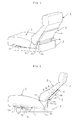
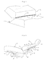
- a seat cushion portion 1 is provided by disposing a seating frame 11 on the bottom of a cushion member while a backrest cushion portion 2 is provided by disposing a back frame 21 on the rear side of the cushion member, as shown in Figures 1 and 2 .
- a rear side upper fringe portion of the seat cushion portion 1 and a bottom side frontal surface of the backrest cushion portion 2 are connected with a connection member C, around which member the backrest cushion portion 2 is foldable with regard to the seat cushion portion 1.
- a highly elastic urethane foam made from diphenylmethane diisocyanate (MDI) is adopted for the cushion member of the seat cushion portion 1 and the backrest cushion portion 2 respectively while a highly rigid metallic pipe is adopted for the seating frame 11 and the back frame 21 respectively.
- MDI diphenylmethane diisocyanate
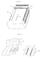
- the cushion member of the seat cushion portion 1 integrally with the seating frame 11 is sheathed with a cover material A while the cushion member of the backrest cushion portion 2 integrally with the back frame 21 embedded therein is sheathed with a cover material A, as shown in Figures 3 and 4 .
- connection member C between the seat cushion portion 1 and the backrest cushion portion 2, which cloth is inserted into a cut opened through the cover A to sheathe the respective cushion portions 1 and 2 with and sewn through the respective cuts so as to form a connection C between those portions, as shown in Figure 5 .
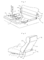
- the seating frame 11 is mounted on the base 3 in such a manner that it is movable to and fro within a fixed area of the base 3, on a rear end portion 11a of which frame, a lower end portion 42 of the bell crank 4 connected slidably in a vertical direction to the back frame 21 to support the cushion portion 2 is pivotally supported.
- a projection 41a of an intermediate link portion 41 is pivotally attached on a raised support potion 31 of the base 3 in such a manner that the bell crank 4 is swingably supported on the base 3.
- bosses R are provided on the back frame 21, which bosses are inserted into the respective guide channels 44 attached on a support plate 43 of the bell crank 4 so that the backrest cushion portion 2 is slidably connected to the bell crank 4.
- the forward sliding of the seat cushion portion 1 from a back position allows the seating frame 11 to pull forwards the lower end portion of the bell crank 4 so as to make the upper portion of the crank 4 tilt backwards, with the result that the backrest cushion portion 2 slides through the bell crank 4 to a reclining position.
- the backward sliding of the seat cushion portion 1 from a front position allows the seating frame 11 to thrust back the lower end portion 42 so as to make the upper portion of the crank 4 tilt upwards, with the result that the backrest cushion portion 2 rises up.
- the seat cushion portion 1 moves to and fro with an upward inclination effected on the frontal side thereof by slanting a guide portion 32 of the base 3 to make the cushion portion 1 slide to and fro.
- the cushion portion 1 automatically slides backwards so as to make the backrest cushion portion 2 raise.
- connection of the seat cushion portion 1 with the backrest cushion portion 2 on the seating side surface prevents a gap from being generated on the seating surface when the cushion portion 2 tilts back, so that a user feels comfortable thereon even during the cushion portion 2 being in a reclining position.
- the formation of the intermediate link portion 41 of the bell crank 4 on the lower side portion thereof allows the upper portion of the crank 4 to abut the backrest cushion portion 2 so as to stably support the portion 2, which acts to disperse the load applied to the portion 2.
- the formation of the support plate 43 arranged on the bell crank 4 permits the cushion portion 2 to be supported on the plate surface, so that the load applied to the cushion potion 2 is effectively dispersed.
- the provision of the projection 41a pivotally attached on the raised support portion 31 on the lower side of the bell crank 4 restrains the to and fro movement of the seat cushion portion 1 according to the tilting back or get-up of the cushion portion 2 to the minimum, so that there is no need to change the position of an ottoman to be disposed in front of the seating portion before or after the cushion portion 2 being reclined.
- a stopper 5 is provided herein, in which a positioning rod 51 is connected to a beam 11b disposed on the frontal end portion of the seating frame 11, which rod is gripped or released with a chuck 52 disposed in the base 3 so as to make the rod 51 fixed at a position as required.
- a wire operating chuck 52 is adopted for the stopper 5, where the rod 51 is released with the chuck 52 upon a lever 53 disposed on the side of the seat cushion portion 1 being pulled up whereas the lever 53 returns to the original position for gripping the rod 51 with the chuck 52 upon the lever 53 being released.
- the stopper 5 does not necessarily comprise the positioning rod 51 and the chuck 52 as mentioned above, but such other mechanism is adopted as allowing the backrest cushion portion 2 to be positioned by a reclining angle as desired, e.g., a ratchet mechanism.
- ceramic coat is applied on the abutment surface of a support plate 43 that is disposed on the upper part of the crank 4 to make such surface less friction-resistant and which surface is opposed to the rear surface of the backrest cushion portion 2, which allows the cushion portion 2 to smoothly slide on the support plate 43.
- the extended formation of the upper part of the bell crank 4 reaching the topmost portion of the cushion portion 2 permits an abutment area between the cushion portion 2 and the support plate to enlarge, so that the backrest cushion portion 2 can be more stably supported.
- a seating frame 11 of the seat cushion portion 1 is made of a plate member, and adhesive members 11c are attached on such member to fix a cushion member to make the plate and cushion members integrated, as shown in Figure 10 .
- connection member C a well-known velvet-type adhesive fastener is adopted instead for the connection member C as a freely attachable and detachable member between the cushion portions 1 and 2.
- the engagement between the backrest cushion portion 2 and the bell crank 4 just provided that they are slidably connected to each other, it may be arranged such that an L-shaped plug-in plate member P is attached on the back frame 21 and such member P is inserted into a receiving slot 45 provided on the support plate 43 of the crank 4, and the back frame 21 of the backrest cushion portion 2 is locally disposed in the cushion member, as shown in Figure 13 .
- the sliding arrangement of the seat cushion portion 1 with respect to the base 3 may be modified, just provided that it moves to and fro within a predetermined range therein, which modification and the like also belong to the technical scope of the invention.
- the reclining seat structure according to the invention remarkably improves on a user's comfortableness in use and excels in safety and convenience to use, so that its industrial marketability and applicability is very high.
Landscapes
- Health & Medical Sciences (AREA)
- Dentistry (AREA)
- General Health & Medical Sciences (AREA)
- Chairs For Special Purposes, Such As Reclining Chairs (AREA)
Applications Claiming Priority (2)
| Application Number | Priority Date | Filing Date | Title |
|---|---|---|---|
| JP2006188156 | 2006-07-07 | ||
| PCT/JP2007/063375 WO2008004583A1 (fr) | 2006-07-07 | 2007-07-04 | Structure de chaise inclinable |
Publications (2)
| Publication Number | Publication Date |
|---|---|
| EP2039265A1 true EP2039265A1 (fr) | 2009-03-25 |
| EP2039265A4 EP2039265A4 (fr) | 2010-08-18 |
Family
ID=38894550
Family Applications (1)
| Application Number | Title | Priority Date | Filing Date |
|---|---|---|---|
| EP07768133A Withdrawn EP2039265A4 (fr) | 2006-07-07 | 2007-07-04 | Structure de chaise inclinable |
Country Status (4)
| Country | Link |
|---|---|
| EP (1) | EP2039265A4 (fr) |
| JP (1) | JP5023314B2 (fr) |
| CN (1) | CN101374439B (fr) |
| WO (1) | WO2008004583A1 (fr) |
Cited By (2)
| Publication number | Priority date | Publication date | Assignee | Title |
|---|---|---|---|---|
| ES2801950A1 (es) * | 2019-07-04 | 2021-01-14 | Suministros Tecnicos De Galicia S L | Mecanismo para pasar una butaca de posicion tumbada a sentada y viceversa |
| DE102019134704A1 (de) * | 2019-12-17 | 2021-06-17 | Grammer Aktiengesellschaft | Fahrzeugsitz |
Families Citing this family (4)
| Publication number | Priority date | Publication date | Assignee | Title |
|---|---|---|---|---|
| US9241571B2 (en) * | 2009-08-18 | 2016-01-26 | Integrated Furniture Technologies Limited | Adjustable furniture |
| EP2341116B1 (fr) | 2009-12-31 | 2016-11-30 | Merz+Benteli AG | Connexion en polymère comprenant une chaîne de polymère et au moins un groupe de silylé relié à une chaîne de polymère |
| JP5634890B2 (ja) * | 2011-01-17 | 2014-12-03 | カリモク家具株式会社 | 椅子 |
| CN105595669B (zh) * | 2016-03-15 | 2017-11-03 | 中源家居股份有限公司 | 一种靠背可调节的沙发 |
Family Cites Families (13)
| Publication number | Priority date | Publication date | Assignee | Title |
|---|---|---|---|---|
| DE2916897A1 (de) * | 1979-04-07 | 1980-11-06 | Otto Zapf | Sitzmoebel |
| JPS5737345U (fr) * | 1980-08-13 | 1982-02-27 | ||
| DE8025516U1 (de) * | 1980-09-24 | 1981-01-15 | Zapf, Otto, 6240 Koenigstein | Sitzmoebel |
| AU541109B2 (en) * | 1981-08-19 | 1984-12-13 | Giroflex Entwicklungs Ag | Chair |
| JPH0330046Y2 (fr) * | 1985-01-30 | 1991-06-26 | ||
| JPS62153934U (fr) * | 1986-03-20 | 1987-09-30 | ||
| DE19639741C2 (de) * | 1996-09-06 | 1998-07-09 | Thomas Jungjohann | Sitzmöbelelement, insbesondere Polstermöbelelement, mit einer gekoppelten Rückenlehnen- und Sitzverstellung |
| JP2000037253A (ja) * | 1998-07-21 | 2000-02-08 | France Bed Co Ltd | 椅 子 |
| JP2000152840A (ja) * | 1998-11-20 | 2000-06-06 | Shiroki Corp | リクライニングチェア |
| JP2000175774A (ja) | 1998-12-18 | 2000-06-27 | Hitachi Ltd | 椅子/ベッド装置 |
| JP4048845B2 (ja) * | 2002-06-17 | 2008-02-20 | 松下電工株式会社 | マッサージ椅子 |
| JP3091157U (ja) * | 2002-07-02 | 2003-01-17 | ウー ドン−ヘー | 腰伸ばし健康椅子の構造 |
| JP4236164B2 (ja) * | 2003-05-21 | 2009-03-11 | 九州日立マクセル株式会社 | マッサージ機 |
-
2007
- 2007-07-04 CN CN200780003199.1A patent/CN101374439B/zh not_active Expired - Fee Related
- 2007-07-04 WO PCT/JP2007/063375 patent/WO2008004583A1/fr not_active Ceased
- 2007-07-04 JP JP2008523712A patent/JP5023314B2/ja active Active
- 2007-07-04 EP EP07768133A patent/EP2039265A4/fr not_active Withdrawn
Cited By (3)
| Publication number | Priority date | Publication date | Assignee | Title |
|---|---|---|---|---|
| ES2801950A1 (es) * | 2019-07-04 | 2021-01-14 | Suministros Tecnicos De Galicia S L | Mecanismo para pasar una butaca de posicion tumbada a sentada y viceversa |
| DE102019134704A1 (de) * | 2019-12-17 | 2021-06-17 | Grammer Aktiengesellschaft | Fahrzeugsitz |
| US11420539B2 (en) | 2019-12-17 | 2022-08-23 | Grammer Ag | Vehicle seat with inclining backrest feature |
Also Published As
| Publication number | Publication date |
|---|---|
| CN101374439A (zh) | 2009-02-25 |
| JPWO2008004583A1 (ja) | 2009-12-03 |
| JP5023314B2 (ja) | 2012-09-12 |
| CN101374439B (zh) | 2010-08-11 |
| EP2039265A4 (fr) | 2010-08-18 |
| WO2008004583A1 (fr) | 2008-01-10 |
Similar Documents
| Publication | Publication Date | Title |
|---|---|---|
| CN101522075B (zh) | 增强可调节性的躺椅 | |
| CN110313743B (zh) | 椅子椅座的向前倾斜组件 | |
| EP2039265A1 (fr) | Structure de chaise inclinable | |
| TW201311188A (zh) | 搖椅及使用於其之彈簧單元 | |
| EP3568046B1 (fr) | Mécanisme de bascule de dos de chaise | |
| CN102555843B (zh) | 座椅结构 | |
| US20080116731A1 (en) | Seat, in Particular Aircraft Passenger Seat | |
| JP2001138998A (ja) | 航空機用座席装置 | |
| JP6041618B2 (ja) | 座席装置 | |
| US20070063563A1 (en) | Tiltable chair accommodating male and female user seating position preferences | |
| JP2015012909A (ja) | 座席装置 | |
| JP2002119347A (ja) | 椅 子 | |
| US20100253122A1 (en) | Seat structure | |
| JP2015163241A (ja) | 椅子 | |
| JP2022177449A (ja) | シート装置 | |
| EP2413745B1 (fr) | Chaise de bureau | |
| JP5983354B2 (ja) | 車両用シート | |
| JP7431551B2 (ja) | 鉄道車両用座席 | |
| JP7352435B2 (ja) | 鉄道車両用座席 | |
| KR200237319Y1 (ko) | 안락소파 | |
| JP2006000144A (ja) | 椅子 | |
| JP3780803B2 (ja) | 椅子 | |
| JP2020049118A (ja) | 椅子 | |
| HK1135578B (en) | Reclining chair with enhanced adjustability | |
| HK1173353B (en) | Reclining chair with enhanced adjustability |
Legal Events
| Date | Code | Title | Description |
|---|---|---|---|
| PUAI | Public reference made under article 153(3) epc to a published international application that has entered the european phase |
Free format text: ORIGINAL CODE: 0009012 |
|
| 17P | Request for examination filed |
Effective date: 20080610 |
|
| AK | Designated contracting states |
Kind code of ref document: A1 Designated state(s): AT BE BG CH CY CZ DE DK EE ES FI FR GB GR HU IE IS IT LI LT LU LV MC MT NL PL PT RO SE SI SK TR |
|
| AX | Request for extension of the european patent |
Extension state: AL BA HR MK RS |
|
| RBV | Designated contracting states (corrected) |
Designated state(s): DE FR GB IT |
|
| A4 | Supplementary search report drawn up and despatched |
Effective date: 20100719 |
|
| DAX | Request for extension of the european patent (deleted) | ||
| 17Q | First examination report despatched |
Effective date: 20120912 |
|
| GRAP | Despatch of communication of intention to grant a patent |
Free format text: ORIGINAL CODE: EPIDOSNIGR1 |
|
| INTG | Intention to grant announced |
Effective date: 20140123 |
|
| STAA | Information on the status of an ep patent application or granted ep patent |
Free format text: STATUS: THE APPLICATION IS DEEMED TO BE WITHDRAWN |
|
| 18D | Application deemed to be withdrawn |
Effective date: 20140201 |