EP2039556A2 - Elektrisch angetriebenes Fahrzeug - Google Patents
Elektrisch angetriebenes Fahrzeug Download PDFInfo
- Publication number
- EP2039556A2 EP2039556A2 EP08253049A EP08253049A EP2039556A2 EP 2039556 A2 EP2039556 A2 EP 2039556A2 EP 08253049 A EP08253049 A EP 08253049A EP 08253049 A EP08253049 A EP 08253049A EP 2039556 A2 EP2039556 A2 EP 2039556A2
- Authority
- EP
- European Patent Office
- Prior art keywords
- velocity
- powered vehicle
- electric powered
- threshold
- control
- Prior art date
- Legal status (The legal status is an assumption and is not a legal conclusion. Google has not performed a legal analysis and makes no representation as to the accuracy of the status listed.)
- Withdrawn
Links
- 230000001172 regenerating effect Effects 0.000 claims abstract description 114
- 238000000034 method Methods 0.000 description 40
- 230000008569 process Effects 0.000 description 34
- 230000001133 acceleration Effects 0.000 description 7
- 238000010586 diagram Methods 0.000 description 4
- 230000005611 electricity Effects 0.000 description 3
- 230000006399 behavior Effects 0.000 description 2
- 230000007423 decrease Effects 0.000 description 2
- 239000013589 supplement Substances 0.000 description 2
- 230000007704 transition Effects 0.000 description 2
- HBBGRARXTFLTSG-UHFFFAOYSA-N Lithium ion Chemical compound [Li+] HBBGRARXTFLTSG-UHFFFAOYSA-N 0.000 description 1
- PXHVJJICTQNCMI-UHFFFAOYSA-N Nickel Chemical compound [Ni] PXHVJJICTQNCMI-UHFFFAOYSA-N 0.000 description 1
- 230000008901 benefit Effects 0.000 description 1
- 230000005540 biological transmission Effects 0.000 description 1
- 239000003990 capacitor Substances 0.000 description 1
- 230000008859 change Effects 0.000 description 1
- 238000010276 construction Methods 0.000 description 1
- 230000003247 decreasing effect Effects 0.000 description 1
- 230000000694 effects Effects 0.000 description 1
- 230000006870 function Effects 0.000 description 1
- 230000006872 improvement Effects 0.000 description 1
- 229910001416 lithium ion Inorganic materials 0.000 description 1
- 230000004048 modification Effects 0.000 description 1
- 238000012986 modification Methods 0.000 description 1
- 229910000652 nickel hydride Inorganic materials 0.000 description 1
- 230000008929 regeneration Effects 0.000 description 1
- 238000011069 regeneration method Methods 0.000 description 1
Images


Classifications
-
- B—PERFORMING OPERATIONS; TRANSPORTING
- B60—VEHICLES IN GENERAL
- B60L—PROPULSION OF ELECTRICALLY-PROPELLED VEHICLES; SUPPLYING ELECTRIC POWER FOR AUXILIARY EQUIPMENT OF ELECTRICALLY-PROPELLED VEHICLES; ELECTRODYNAMIC BRAKE SYSTEMS FOR VEHICLES IN GENERAL; MAGNETIC SUSPENSION OR LEVITATION FOR VEHICLES; MONITORING OPERATING VARIABLES OF ELECTRICALLY-PROPELLED VEHICLES; ELECTRIC SAFETY DEVICES FOR ELECTRICALLY-PROPELLED VEHICLES
- B60L7/00—Electrodynamic brake systems for vehicles in general
- B60L7/10—Dynamic electric regenerative braking
- B60L7/16—Dynamic electric regenerative braking for vehicles comprising converters between the power source and the motor
-
- B—PERFORMING OPERATIONS; TRANSPORTING
- B60—VEHICLES IN GENERAL
- B60L—PROPULSION OF ELECTRICALLY-PROPELLED VEHICLES; SUPPLYING ELECTRIC POWER FOR AUXILIARY EQUIPMENT OF ELECTRICALLY-PROPELLED VEHICLES; ELECTRODYNAMIC BRAKE SYSTEMS FOR VEHICLES IN GENERAL; MAGNETIC SUSPENSION OR LEVITATION FOR VEHICLES; MONITORING OPERATING VARIABLES OF ELECTRICALLY-PROPELLED VEHICLES; ELECTRIC SAFETY DEVICES FOR ELECTRICALLY-PROPELLED VEHICLES
- B60L50/00—Electric propulsion with power supplied within the vehicle
- B60L50/50—Electric propulsion with power supplied within the vehicle using propulsion power supplied by batteries or fuel cells
- B60L50/51—Electric propulsion with power supplied within the vehicle using propulsion power supplied by batteries or fuel cells characterised by AC-motors
-
- B—PERFORMING OPERATIONS; TRANSPORTING
- B60—VEHICLES IN GENERAL
- B60L—PROPULSION OF ELECTRICALLY-PROPELLED VEHICLES; SUPPLYING ELECTRIC POWER FOR AUXILIARY EQUIPMENT OF ELECTRICALLY-PROPELLED VEHICLES; ELECTRODYNAMIC BRAKE SYSTEMS FOR VEHICLES IN GENERAL; MAGNETIC SUSPENSION OR LEVITATION FOR VEHICLES; MONITORING OPERATING VARIABLES OF ELECTRICALLY-PROPELLED VEHICLES; ELECTRIC SAFETY DEVICES FOR ELECTRICALLY-PROPELLED VEHICLES
- B60L7/00—Electrodynamic brake systems for vehicles in general
- B60L7/10—Dynamic electric regenerative braking
- B60L7/14—Dynamic electric regenerative braking for vehicles propelled by AC motors
-
- B—PERFORMING OPERATIONS; TRANSPORTING
- B60—VEHICLES IN GENERAL
- B60L—PROPULSION OF ELECTRICALLY-PROPELLED VEHICLES; SUPPLYING ELECTRIC POWER FOR AUXILIARY EQUIPMENT OF ELECTRICALLY-PROPELLED VEHICLES; ELECTRODYNAMIC BRAKE SYSTEMS FOR VEHICLES IN GENERAL; MAGNETIC SUSPENSION OR LEVITATION FOR VEHICLES; MONITORING OPERATING VARIABLES OF ELECTRICALLY-PROPELLED VEHICLES; ELECTRIC SAFETY DEVICES FOR ELECTRICALLY-PROPELLED VEHICLES
- B60L7/00—Electrodynamic brake systems for vehicles in general
- B60L7/24—Electrodynamic brake systems for vehicles in general with additional mechanical or electromagnetic braking
- B60L7/26—Controlling the braking effect
-
- B—PERFORMING OPERATIONS; TRANSPORTING
- B60—VEHICLES IN GENERAL
- B60L—PROPULSION OF ELECTRICALLY-PROPELLED VEHICLES; SUPPLYING ELECTRIC POWER FOR AUXILIARY EQUIPMENT OF ELECTRICALLY-PROPELLED VEHICLES; ELECTRODYNAMIC BRAKE SYSTEMS FOR VEHICLES IN GENERAL; MAGNETIC SUSPENSION OR LEVITATION FOR VEHICLES; MONITORING OPERATING VARIABLES OF ELECTRICALLY-PROPELLED VEHICLES; ELECTRIC SAFETY DEVICES FOR ELECTRICALLY-PROPELLED VEHICLES
- B60L2250/00—Driver interactions
- B60L2250/24—Driver interactions by lever actuation
-
- Y—GENERAL TAGGING OF NEW TECHNOLOGICAL DEVELOPMENTS; GENERAL TAGGING OF CROSS-SECTIONAL TECHNOLOGIES SPANNING OVER SEVERAL SECTIONS OF THE IPC; TECHNICAL SUBJECTS COVERED BY FORMER USPC CROSS-REFERENCE ART COLLECTIONS [XRACs] AND DIGESTS
- Y02—TECHNOLOGIES OR APPLICATIONS FOR MITIGATION OR ADAPTATION AGAINST CLIMATE CHANGE
- Y02T—CLIMATE CHANGE MITIGATION TECHNOLOGIES RELATED TO TRANSPORTATION
- Y02T10/00—Road transport of goods or passengers
- Y02T10/60—Other road transportation technologies with climate change mitigation effect
- Y02T10/70—Energy storage systems for electromobility, e.g. batteries
Definitions
- the present invention relates to electric powered vehicles performing drive control and regenerative control using an electric motor-
- an electric powered vehicle running by transmitting a driving power or braking power generated by an electric motor to wheels.
- the driving power in such a vehicle is obtained by applying a predetermined voltage to the motor, while the braking power is obtained by using the electric motor as a load.
- the braking power is obtained, for example by using the electric motor as an electricity generator and converting the kinetic energy of a wheel into the electric energy, thereby imparting a torque in the opposite direction to the rotating direction to the motor (i.e. the torque works as a load).
- the control for obtaining the braking power using an electric motor as a load in such a manner is hereinafter referred to as regenerative control.
- the electric powered vehicle with a function of the regenerative control has a usage state in which a user makes the electric powered vehicle run by performing the drive control (hereinafter referred to as “running state”), and a usage state in which a user makes the electric powered vehicle move by pushing it without performing the drive control or braking (hereinafter referred to as "pushed state").
- running state a usage state in which a user makes the electric powered vehicle run by performing the drive control
- pushed state a usage state in which a user makes the electric powered vehicle move by pushing it without performing the drive control or braking
- the electric motor connected to the wheel works as a electricity generator (a load), and therefore the regenerative control is performed, whereby the braking power works on the wheel.
- the user is subjected to a great load, and in the case where the user does not have enough strength, it is problematic because the electric powered vehicle cannot be moved.
- the regenerative control is prohibited at or below the predetermined velocity, the regenerative control is performed only at the velocity higher than the predetermined velocity. Accordingly, the regenerative control is prohibited even when a user wants to utilize the regenerative control at or below the predetermined velocity (for example, when the running velocity of the electric powered vehicle is decreased, or when a user wants to utilize the braking power by the regenerative control on a sloping road). This can cause a problem of a low regenerative efficiency because the regenerative energy cannot be retrieved at or below the predetermined velocity.
- An object of the present invention is to provide an electric powered vehicle capable of performing regenerative control even when a user wants to utilize the regenerative control at or below a predetermined velocity, and thereby realizing a high regenerative efficiency.
- the present invention provides an electric powered vehicle running by performing a drive control for transmitting a driving power obtained when an electric motor works as a driving power source to a wheel, and a regenerative control for transmitting a braking power obtained when the electric motor works as a load to the wheel, wherein when a first velocity threshold is Vt1 and a second velocity threshold is Vt2, and when the thresholds are Vt1 ⁇ Vt2, the regenerative control is permitted in the case where a running velocity increases to or above the second velocity, and the regenerative control is prohibited in the case where the running velocity falls below the first velocity threshold.
- an electric powered vehicle comprising a wheel for running on a road, an electric motor for transmitting driving power or braking power to the wheel, a control part for performing a drive control for transmitting driving power to the wheel with the electric motor working as a power source and a regenerative control for transmitting braking power to the wheel with the electric motor working as a load, and a velocity detecting part for detecting a running velocity, when a first velocity threshold is Vt1 and a second velocity threshold is Vt2, and when the thresholds are Vt1 ⁇ Vt2, in the regenerative control, the control part permits the regenerative control in the case where the velocity increases to or above the second velocity threshold Vt2, and thereafter it keeps the permission of the regenerative control until the velocity falls below the first velocity threshold Vt1.
- an electric powered vehicle comprising a wheel for running on a road, an electric motor for transmitting driving power or braking power to the wheel, and a control part for performing a drive control for transmitting driving power to the wheel with the electric motor working as a power source and a regenerative control for transmitting braking power to the wheel with the electric motor working as a load
- a velocity detecting part for detecting a running velocity, when a first velocity threshold is Vt1, a second velocity threshold is Vt2, and a third velocity threshold is Vt3, and when the thresholds are Vt1 ⁇ Vt2 ⁇ vt3, in the regenerative control
- the control part permits the regenerative control in the case where the velocity increases to or above the second velocity threshold Vt2, and thereafter in the case where the velocity increases to or above the third velocity threshold Vt3, it keeps the permission of the regenerative control until the velocity falls below the first velocity threshold Vt1.
- the control part permits the regenerative control in the case where the velocity increases to or above the second velocity threshold Vt2, and thereafter in the case where the velocity does not increase to or above the third velocity threshold Vt3, it keeps the permission of the regenerative control until the velocity falls below the second velocity threshold Vt2.
- the second velocity threshold Vt2 is 4 km/h or above and below 6 km/h.
- control part comprises a memorizing part for memorizing a value corresponding to each of the velocity thresholds, and a changing unit for changing at least the value corresponding to the second velocity threshold Vt2 among the values corresponding to the velocity thresholds memorized in the memorizing part.
- the electric powered vehicle of the present invention has the configurations described above, once the velocity increases to or above a given velocity threshold, the regenerative control is performed even in the case where the velocity is below a predetermined velocity (the second velocity threshold), thereby realizing improvement of the regenerative efficiency.
- the present invention is an electric powered vehicle running by transmitting a driving power or braking power generated by an electric motor to a wheel, and controlling the driving power or the braking power, the electric powered vehicle determining a pushed state and a running state to control appropriately to the state.
- Basic ideas of the present invention are described below.
- a first velocity threshold Vt1, a second threshold velocity Vt2, and a third velocity threshold Vt3 are set so that the velocity thresholds are Vt1 ⁇ vt2 ⁇ Vt3.
- the electric powered vehicle is determined to be whether in the pushed state or the running state based on the velocity thresholds. Further, when the electric powered vehicle is in the pushed state, it is determined whether the state is an easily pushed state or a difficultly pushed state, whereby regenerative control is permitted or prohibited.
- the "easily pushed state” and the "difficultly pushed state” are described below.
- the "easily pushed state” is a state where it can be determined that the electric powered vehicle is in the pushed state, and the velocity of the electric powered vehicle is low, whereby the electric powered vehicle can be moved by being pushed easily.
- the regenerative control is performed in such a state, a user is subjected to a great load because the braking power works as a load when the electric powered vehicle is pushed. Accordingly, when the electric powered vehicle is in the easily pushed state, the regenerative control is prohibited.
- the general walking speed of a person is below 4 km/h, and therefore it can be determined that the electric powered vehicle can be moved easily by being pushed when the velocity is below 4 km/h.
- the "difficultly pushed state” is a state where it can be determined that the electric powered vehicle is in the pushed state, with the higher velocity of the electric powered vehicle than in the easily pushed state, and it is difficult to lower the velocity due to inertial force of the electric powered vehicle when the electric powered vehicle is moving by being pushed (i.e. the state where it is difficult to move the electric powered vehicle by pushing it). Accordingly, when the electric powered vehicle is in the difficultly pushed state, the regenerative control is performed also in order to lighten the load for the user. In particular, it is determined that the electric powered vehicle is in the difficultly pushed state when the velocity reaches a velocity which is judged to be a fast walking speed (4 km/h or above and below 6 km/h).
- the braking power works on the electric powered vehicle and therefore the velocity increase can be prevented, thereby lightening the load on the user pushing the electric powered vehicle.
- the braking power works on the electric powered vehicle and therefore the velocity increase can be prevented, whereby the electric powered vehicle can be stopped more easily, and therefore safety is improved.
- This running state is a state where the drive control is performed to make the electric powered vehicle run as described above.
- the electric powered vehicle is in the running state when the electric powered vehicle is moving with a velocity with which a user cannot move the electric powered vehicle by pushing it (for example it is 8 km/h because a jogging speed is 6 km/h or above).
- the electric powered vehicle has to be once stopped so that a user gets off the vehicle and then starts pushing the vehicle.
- the electric powered vehicle is determined to be in the running state, even if the velocity of the electric powered vehicle falls to such a low velocity as in the easily pushed state, it is determined that the electric powered vehicle is still in the running state until the vehicle stops.
- the electric powered vehicle is determined to be in the running state, the user is on the vehicle. Therefore, even with such a low velocity as in the easily pushed state, the user will not be subjected to a load. Accordingly, even with such a low velocity as in the easily pushed state, in the running state, the regenerative control is permitted since it is desirable to perform the regenerative control.
- the regenerative control is performed to retrieve the regenerative energy, thereby improving the regenerative efficiency.
- the regenerative control is prohibited until the running velocity of the electric powered vehicle increases to or above the second velocity threshold Vt2. And then when the velocity increases to or above the second velocity threshold Vt2, it is determined that the electric powered vehicle is in the difficultly pushed state and the regenerative control is permitted. And then, when the velocity further increases to or above the third velocity threshold Vt3, the electric powered vehicle is determined to be in the running state. Once the electric powered vehicle is determined to be in the running state, even when the velocity falls below the second velocity threshold Vt2, the regenerative control is permitted unless the velocity falls below the first velocity threshold Vt1. And then, when the velocity falls below the first velocity threshold Vt1, it is determined that the electric powered vehicle stops and the state of the electric powered vehicle is shifted from the running state to the easily pushed state, and the regenerative control is prohibited.
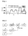
- Fig. 1 shows a velocity transition of an electric powered vehicle when such control described above is performed and a state of the regenerative control as to whether it is permitted or prohibited.
- the vertical axis of the graph is for the velocity of the electric powered vehicle and the horizontal axis is for the time.
- the dashed line shows a state where the regenerative control is prohibited
- the solid line shows a state where the regenerative control is permitted.
- the electric powered vehicle has both a period in the easily pushed state and a period in the difficultly pushed state (i.e. there is some duration with the velocity at or above the second velocity threshold), and therefore the regenerative control is permitted during the period with the velocity being at or above the second velocity threshold Vt2, and is prohibited during the period with the velocity being below the second velocity threshold Vt2.
- the velocity once increases to or above the third velocity threshold Vt3, whereby the electric powered vehicle is determined to be in the running state.
- the regenerative control is permitted from the time when the velocity increases to or above the second velocity threshold vt2 to the time when it is determined that the electric powered vehicle stops and is again shifted to the easily pushed state (i.e. even when the velocity falls below the second velocity threshold Vt2, the regenerative control is still permitted, and is prohibited when the velocity falls below the first velocity threshold Vt1).
- the first velocity threshold Vt1 is used as a threshold for determining that the electric powered vehicle is shifted from the running state to the easily pushed state.
- a user stops the electric powered vehicle before the user starts walking, and therefore, the velocity is thought to decrease extremely. Accordingly, it is desirable to set the first threshold to a velocity well below the usual walking speed for a person (for example, 2 to 4 km/h), for example, 1 km/h.
- the second velocity threshold Vt2 is used as a threshold for determining that the electric powered vehicle is shifted from the easily pushed state to the difficultly pushed state (i.e. a velocity threshold with which it can be determined that it is difficult to move the electric powered vehicle by pushing it).
- a velocity threshold with which it can be determined that it is difficult to move the electric powered vehicle by pushing it.
- the second velocity threshold Vt2 it is desirable to set the second velocity threshold Vt2 to 4 km/h or above and below 6 km/h, which is the velocity which can be determined to be a fast walking speed of a person.
- the third velocity threshold Vt3 is used to determine that the motor of the electric powered vehicle is under drive control and the vehicle is in the running state. Therefore, it is desirable to set the third threshold to a velocity with which a user cannot move the electric powered vehicle by pushing it.
- a jogging speed is said to be 6 km/h or above, and therefore, for example the third velocity threshold Vt3 can be set to 8 km/h with a margin.
- the regenerative control is prohibited, thereby enabling a user to move the electric powered vehicle without the braking power of the braking control working when the user is moving the vehicle by pushing it.
- the velocity of the electric powered vehicle is increased to such velocity as in the difficultly pushed state, the braking power works on the electric powered vehicle while the vehicle is moving by being pushed, whereby the vehicle can be stopped easily, and therefore safety is improved.
- the regenerative control is permitted even in the case where the velocity of the electric powered vehicle is as low as in the easily pushed state, thereby enabling the electric powered vehicle to retrieve the regenerative energy during running, thereby realizing high regenerative efficiency.
- the regenerative control of the first embodiment described above is performed using only the first velocity threshold Vt1 and the second velocity threshold Vt2, without the third velocity threshold Vt3.
- the electric powered vehicle is determined to be in the difficultly pushed state, and the regenerative control is permitted.
- the regenerative control is still permitted.
- the velocity is determined that the electric powered vehicle stops and the state thereof is shifted from the running state to the easily pushed state, and the regenerative control is prohibited.
- the regenerative control is prohibited, and therefore a user can move the electric powered vehicle without the braking power working when the user moves the vehicle by pushing it. Further, once the electric powered vehicle enters the difficultly pushed state, the braking power works until the electric powered vehicle stops (i.e. it is determined that the regenerative control is desired even when the velocity is below a predetermined threshold), whereby the electric powered vehicle can be stopped safely even when the velocity suddenly increases due to a slope or the like.
- the electric powered vehicle can retrieve the regenerative energy, thereby realizing high regenerative efficiency.
- the embodiment 1 of the present invention is described below with reference to the drawings.
- the electric powered vehicle of the embodiment 1 as illustrated in the configuration diagram of the electric powered vehicle shown in Fig. 2 , comprises a battery 1, an electric power converting device 2, an electric motor 3, a drive wheel 4, a control part 5, an accelerator 6, a brake 7, and a rotation sensor 8.
- the battery 1 is an electric power source such as a lithium-ion battery, a nickel hydride, a lead storage battery, or a capacitor.
- the electric power from the battery 1 is converted into the required electric power by the electric power converting device 2 and then supplied to the motor 3.
- the electric power generated when the motor 3 performs the regeneration is converted into the required electric power to charge the battery 1.
- the motor 3 is an AC motor, an inverter is applied.
- the motor 3 rotates by being supplied with the electric power converted by the electric power converting device 2, and transmits the rotation to the drive wheel 4.
- the accelerator 6 is configured to be operated by rotation of a grip attached to a handle (not shown).
- the accelerator 6 detects the amount of the rotation from the rotation of the grip, and then transmits the amount of the rotation to the control part 5.
- the amount of the rotation can be detected by using a sensor for detecting an angle such as a rotary potentiometer.
- the amount of the rotation of the grip is an accelerator divergence. When the accelerator divergence is zero, it shows that the grip is not rotated from the reference point (i.e. acceleration OFF state), and the greater the accelerator divergence is, the greater the amount of the grip rotation from the reference point it shows (i.e. acceleration ON state).
- the accelerator divergence transmitted to the control part 5 is used for command torque calculation when the drive control is performed.
- the brake 7 is configured, for example, to be operated by a user pulling a handle lever (not shown) provided with the handle.
- a signal is outputted to notify the control part 5 that a braking operation has been conducted. This signal is used when the electric powered vehicle is controlled by the drive control or the brake control of the motor.
- the rotation sensor 8 transmits the number of rotations of the motor to the control part 5.
- the transmitted number of rotations is used for calculating the velocity of the electric powered vehicle.
- the control part 5 controls the electric powered vehicle by determining whether performing the drive control, the regenerative control, or no control on the motor 3, on the basis of the accelerator divergence of the accelerator 6 and operation state of the brake 7. The specific way of determination is to be described later.
- the velocity of the electric powered vehicle is calculated from the number of rotations of the motor obtained by the rotation sensor 8. And then a command torque is calculated from the calculated velocity and the accelerator divergence, and the electric power converting device 2 is controlled to provide a torque in accordance with the command torque to perform the drive control on the motor.
- the electric power converting device 2 converts the electricity so that the required voltage can be obtained in accordance with the state of charge (SOC) of the battery 1 and the number of rotations of the motor to charge the battery 1.
- SOC can be obtained by, for example, detecting a voltage by using a detecting part (not shown) for detecting the voltage of the battery.
- the electric power converting device 2 and the motor 3 are disconnected electrically so that there is no electric power transmission therebetween.
- the control part 5 preliminarily memorizes in an internal memory (not shown) a first velocity threshold Vt1, a second velocity threshold Vt2, and a third velocity threshold Vt3, which are Vt1 ⁇ Vt2 ⁇ Vt3. These velocity thresholds are used for determining the permission or prohibition of the regenerative control to be described later.
- the control part 5 can memorize the velocity itself, but instead a value corresponding to the velocity such as the number of rotations of the motor can be memorized. Also, these values can be changeable as to be described later.
- Fig. 3 shows a control process of the electric powered vehicle.
- the control part determines whether or not a brake operation is conducted in step S11.
- the process proceeds to step S12 and it is determined whether or not the accelerator divergence is smaller than a threshold tha.
- the threshold tha is a threshold for determining whether the acceleration is ON or OFF. Therefore, when the accelerator divergence is greater than the threshold tha, the acceleration can be determined to be ON, and when the accelerator divergence is smaller than the threshold tha, the acceleration can be determined to be OFF.
- the accelerator divergence is determined to be greater than the threshold tha in this step, the acceleration is ON, and in such a case, the drive control is performed in step S13 and the process returns to step S11.
- step S14 When it is determined that the brake operation is conducted in step S11, and also that the accelerator divergence is determined to be smaller than the threshold tha (i.e. the acceleration is OFF), it is further determined whether or not the regenerative control is prohibited in step S14. The determination of the permission and prohibition of the regenerative control is to be described later.
- the regenerative control is permitted (i.e. determined NO) in step S14, the regenerative control is performed in step S15, and the process returns to step S11.
- the process proceeds to step S16 and no control is performed.
- Fig. 4 shows a determination process of permission and prohibition of the regenerative control in the embodiment 1.
- a series of steps from START to END provide a procedure for determination, and this determination process is conducted regularly. Also, this process is conducted in parallel with the control process of the electric powered vehicle shown in Fig. 3 , and the results of steps S108 and S105 to be discussed later are used in the determination of step S14 in Fig. 3 .
- step S101 the control part 5 calculates the velocity of the electric powered vehicle from the number of rotations obtained by the rotation sensor 8, and determines whether or not the calculated velocity is lower than the first velocity threshold Vt1 (i.e. determination whether or not the electric powered vehicle is in the stopped state).
- the velocity is determined to be lower than the first velocity threshold Vt1 (the electric powered vehicle is in the stopped state)
- a flag is set to zero (S106), and the regenerative control is prohibited (S108), and then the process ends.
- the flag is for determining whether or not the electric powered vehicle is in a running state. When the flag is zero, it shows that the electric powered vehicle is not in the running state (for example, in the pushed state), and when the flag is one, it shows that the electric powered vehicle is in the running state.
- step S102 it is determined whether or not the velocity is lower than the second velocity threshold Vt2 (i.e. determination of whether the electric powered vehicle is in the easily pushed state or in the difficultly pushed state).
- step S107 it is determined whether or not the flag is zero in step S107 (i.e. determination of whether or not the electric powered vehicle is in the running state).
- step S103 it is determined whether or not the velocity is lower than the third velocity threshold Vt3 (i.e. determination of whether the electric powered vehicle is in the difficultly pushed state or in the running state).
- the regenerative control is permitted (S105) and the process ends.
- the flag is set to one (S104), the regenerative control is permitted (S105), and then the process ends.
- the electric powered vehicle runs with a velocity of or above the third velocity threshold Vt3, the electric powered vehicle is determined to be in the running state, and therefore, the regenerative control is performed even when the velocity decreases, thereby increasing the regenerative efficiency.
- the regenerative control is permitted in the case where the velocity increases to or above the second velocity threshold Vt2. Therefore, in the case where the velocity of the electric powered vehicle increases due to a factor such as a downhill, the load can be lightened for a user pushing the electric powered vehicle, and in the case where the velocity of the electric powered vehicle increases too much, the electric powered vehicle can be stopped easily. And such behaviors increase safety.
- the regenerative control is not performed, thereby enabling a user to move the vehicle by pushing it without being subjected to a load.
- the control is conducted by determining the permission and prohibition of the regenerative control of the electric powered vehicle using the first velocity threshold Vt1 to the third velocity threshold Vt3.
- the control is conducted by determining the permission and prohibition of the regenerative control of the electric powered vehicle without using the third velocity threshold Vt3.
- the configuration of the electric powered vehicle and the control process of the embodiment 2 are the same as the configuration of the electric powered vehicle ( Fig. 2 ) and the control process ( Fig. 3 ) of the embodiment 1, and therefore the description thereof is omitted.
- Fig. 5 shows a process of determining the permission and prohibition of the regenerative control in the embodiment 2. Compared to the control process of the embodiment 1 ( Fig. 4 ), this process in the embodiment 2 does not have the determination of step S103.
- step S201 the control part 5 calculates the velocity of the electric powered vehicle from the number of rotations obtained by the rotation sensor 8, and determines whether or not the calculated velocity is lower than the first velocity threshold Vt1 (i.e. determination whether or not the electric powered vehicle is in the stopped state).
- the velocity is determined to be lower than the first velocity threshold Vt1 (i.e. the electric powered vehicle is in the stopped state)
- a flag is set to zero (S205), and the regenerative control is prohibited (S207), and then the process ends.
- the flag is for determining whether or not the electric powered vehicle is in the difficultly pushed state.
- the flag is zero, it shows that the electric powered vehicle is not in the difficultly pushed state (for example, in the easily pushed state), and when the flag is one, it shows that the electric powered vehicle is in the difficultly pushed state.
- step S202 it is determined whether or not the velocity is lower than the second velocity threshold Vt2 (i.e. determination of whether the electric powered vehicle is in the easily pushed state or in the difficultly pushed state).
- step S206 it is determined whether or not the flag is zero in step S206 (i.e. determination of whether or not in the difficultly pushed state).
- step S202 When it is determined that the velocity is at or above the second velocity threshold Vt2 (i.e. the difficultly pushed state) in step S202, the flag is set to one (S203), and the regenerative control is permitted (S204) and the process ends.
- Vt2 i.e. the difficultly pushed state
- the regenerative control is permitted in the case where the velocity increases to or above the second velocity threshold Vt2. Therefore, in the case where the velocity of the electric powered vehicle increases due to a factor such as a downhill, the load can be lightened for a user pushing the electric powered vehicle, and in the case where the velocity of the electric powered vehicle increases too much, the electric powered vehicle can be stopped easily. And such behaviours increase safety. Further, once the electric powered vehicle is in the difficultly pushed state, the braking power works until the electric powered vehicle stops (in the stopped state), whereby the electric powered vehicle can be stopped safely even when the velocity suddenly increases due to a slope or the like.
- the regenerative control is not performed, thereby enabling a user to move the vehicle by pushing it without being subjected to a load.
- the regenerative control is permitted and the permission is kept until the electric powered vehicle is actually in the stopped state, thereby increasing the regenerative efficiency.
- the brake operation is described with an example operated with a lever being pulled, which is provided with a handle, but not limited to this example.
- the brake can be configured to be operated using a pedal.
- a signal for transmitting that the brake is applied is outputted to a control part.
- the velocity thresholds are preliminarily memorized, but they can be configured so that a user can change the velocity thresholds.
- a velocity threshold setting part 9 is provided.
- Fig. 7 shows an example of the velocity threshold setting part.
- the velocity threshold setting part 9 comprises, for example, a display part 91 for displaying a velocity threshold, and a velocity threshold entering part 92 which includes a numerical keypad, an arrow key, and an enter key which are needed for entering the velocity threshold.
- a user sets the velocity thresholds by entering the velocity thresholds (the first velocity threshold to the third velocity threshold) with the velocity threshold entering part while checking the display part.
- the velocity threshold setting part 9 can be designed to be stored under a chair or the like usually, and taken out to set a velocity threshold when the setting is needed.
- the display part can be combined with a trip meter or the like and the display can be switched for setting a velocity threshold when the setting is needed.
- velocity thresholds which vary among individuals can be set on an individual basis.
- the velocities which vary among individuals can be the walking speed, fast walking speed, and jogging speed, and they are considered in the setting of the first velocity threshold Vt1, the second velocity threshold Vt2, and the third velocity threshold Vt3 respectively.
- the second velocity threshold Vt2 is a threshold for obtaining a support by the regenerative control. Therefore, by allowing the second velocity threshold Vt2 to be changeable, the difference among individuals can be absorbed and thereby improving safety.
Landscapes
- Engineering & Computer Science (AREA)
- Power Engineering (AREA)
- Transportation (AREA)
- Mechanical Engineering (AREA)
- Life Sciences & Earth Sciences (AREA)
- Sustainable Development (AREA)
- Sustainable Energy (AREA)
- Physics & Mathematics (AREA)
- Electromagnetism (AREA)
- Electric Propulsion And Braking For Vehicles (AREA)
Applications Claiming Priority (1)
| Application Number | Priority Date | Filing Date | Title |
|---|---|---|---|
| JP2007244534A JP4877827B2 (ja) | 2007-09-20 | 2007-09-20 | 電動車輌 |
Publications (2)
| Publication Number | Publication Date |
|---|---|
| EP2039556A2 true EP2039556A2 (de) | 2009-03-25 |
| EP2039556A3 EP2039556A3 (de) | 2011-02-16 |
Family
ID=40210563
Family Applications (1)
| Application Number | Title | Priority Date | Filing Date |
|---|---|---|---|
| EP08253049A Withdrawn EP2039556A3 (de) | 2007-09-20 | 2008-09-17 | Elektrisch angetriebenes Fahrzeug |
Country Status (3)
| Country | Link |
|---|---|
| US (1) | US8134314B2 (de) |
| EP (1) | EP2039556A3 (de) |
| JP (1) | JP4877827B2 (de) |
Cited By (4)
| Publication number | Priority date | Publication date | Assignee | Title |
|---|---|---|---|---|
| EP2724924A1 (de) * | 2012-10-29 | 2014-04-30 | Taiyo Yuden Co., Ltd. | Motorsteuerung und Fahrzeug mit Hilfsantrieb |
| US9136780B2 (en) | 2012-09-24 | 2015-09-15 | Taiyo Yuden Co., Ltd. | Controller for driving a motor and electric power-assisted vehicle |
| EP2868562A4 (de) * | 2012-06-28 | 2016-03-02 | Murata Manufacturing Co | Steuervorrichtung einer bewegungsvorrichtung mit hilfsaggregat und bewegungsvorrichtung mit hilfsaggregat mit dieser steuervorrichtung |
| IT201700003184A1 (it) * | 2017-01-13 | 2018-07-13 | Zehus S P A | Sistema adattativo per il controllo di una bicicletta a pedalata assistita |
Families Citing this family (3)
| Publication number | Priority date | Publication date | Assignee | Title |
|---|---|---|---|---|
| JP2010257750A (ja) * | 2009-04-24 | 2010-11-11 | Sanyo Electric Co Ltd | バッテリモジュール、バッテリシステムおよび電動車両 |
| JP2010257775A (ja) * | 2009-04-24 | 2010-11-11 | Sanyo Electric Co Ltd | バッテリモジュール、バッテリシステムおよび電動車両 |
| GB2549740B (en) * | 2016-04-26 | 2019-04-17 | Dyson Technology Ltd | A method for controlling an electric motor |
Citations (1)
| Publication number | Priority date | Publication date | Assignee | Title |
|---|---|---|---|---|
| JP2001025101A (ja) | 1999-07-07 | 2001-01-26 | Atex Co Ltd | 電動車の安全制御装置 |
Family Cites Families (10)
| Publication number | Priority date | Publication date | Assignee | Title |
|---|---|---|---|---|
| US3720863A (en) * | 1969-08-27 | 1973-03-13 | Allis Chalmers | Electrically driven vehicle steered by control of power and speed of tractive elements |
| JPS5416006B2 (de) * | 1973-01-29 | 1979-06-19 | ||
| US4111274A (en) | 1975-08-11 | 1978-09-05 | M. Dale King | Electrically-powered tricycle |
| US5565760A (en) * | 1994-11-02 | 1996-10-15 | General Electric Company | Electrical propulsion systems for a golf car |
| JP3441552B2 (ja) * | 1995-03-17 | 2003-09-02 | 日本輸送機株式会社 | 電気式車両の速度制御装置 |
| JP2000118477A (ja) | 1998-10-12 | 2000-04-25 | Sony Corp | 助力機能付き自転車 |
| US6462506B2 (en) * | 1999-12-30 | 2002-10-08 | Textron Inc. | Electric golf car with low-speed regenerative braking |
| JP4518301B2 (ja) * | 2001-02-28 | 2010-08-04 | 本田技研工業株式会社 | 電動補助自転車の制御装置 |
| JP2006015887A (ja) | 2004-07-02 | 2006-01-19 | Sanyo Electric Co Ltd | 電動補助自転車 |
| US8280569B2 (en) * | 2004-12-09 | 2012-10-02 | General Electric Company | Methods and systems for improved throttle control and coupling control for locomotive and associated train |
-
2007
- 2007-09-20 JP JP2007244534A patent/JP4877827B2/ja not_active Expired - Fee Related
-
2008
- 2008-09-16 US US12/211,346 patent/US8134314B2/en not_active Expired - Fee Related
- 2008-09-17 EP EP08253049A patent/EP2039556A3/de not_active Withdrawn
Patent Citations (1)
| Publication number | Priority date | Publication date | Assignee | Title |
|---|---|---|---|---|
| JP2001025101A (ja) | 1999-07-07 | 2001-01-26 | Atex Co Ltd | 電動車の安全制御装置 |
Cited By (7)
| Publication number | Priority date | Publication date | Assignee | Title |
|---|---|---|---|---|
| EP2868562A4 (de) * | 2012-06-28 | 2016-03-02 | Murata Manufacturing Co | Steuervorrichtung einer bewegungsvorrichtung mit hilfsaggregat und bewegungsvorrichtung mit hilfsaggregat mit dieser steuervorrichtung |
| US9136780B2 (en) | 2012-09-24 | 2015-09-15 | Taiyo Yuden Co., Ltd. | Controller for driving a motor and electric power-assisted vehicle |
| EP2724924A1 (de) * | 2012-10-29 | 2014-04-30 | Taiyo Yuden Co., Ltd. | Motorsteuerung und Fahrzeug mit Hilfsantrieb |
| US8725340B1 (en) | 2012-10-29 | 2014-05-13 | Taiyo Yuden Co., Ltd. | Motor drive controller and electric power-assisted vehicle |
| CN103786825A (zh) * | 2012-10-29 | 2014-05-14 | 太阳诱电株式会社 | 电动机驱动控制装置及电动助力车 |
| CN103786825B (zh) * | 2012-10-29 | 2017-01-04 | 太阳诱电株式会社 | 电动机驱动控制装置及电动助力车 |
| IT201700003184A1 (it) * | 2017-01-13 | 2018-07-13 | Zehus S P A | Sistema adattativo per il controllo di una bicicletta a pedalata assistita |
Also Published As
| Publication number | Publication date |
|---|---|
| US20090079369A1 (en) | 2009-03-26 |
| JP4877827B2 (ja) | 2012-02-15 |
| EP2039556A3 (de) | 2011-02-16 |
| US8134314B2 (en) | 2012-03-13 |
| JP2009077549A (ja) | 2009-04-09 |
Similar Documents
| Publication | Publication Date | Title |
|---|---|---|
| KR102574116B1 (ko) | 차량 및 그 제어 방법 | |
| CN101835654B (zh) | 基于蓄电池充电状态的混合动力牵引链驱动方法 | |
| CA2691990C (en) | Control apparatus for hybrid vehicle | |
| KR102542523B1 (ko) | 브레이크 시스템 및 그 제어 방법 | |
| US8725339B2 (en) | Method for controlling a hybrid traction assembly and hybrid vehicle controlled according to such a method | |
| JP5826402B2 (ja) | ハイブリッド車両 | |
| US8134314B2 (en) | Electric powered vehicle | |
| US8820445B2 (en) | Charge/discharge control device and charge/discharge control method for power storage device, and electric-powered vehicle | |
| KR102270490B1 (ko) | 하이브리드 차량의 제어 방법 및 제어 장치 | |
| US20110202248A1 (en) | Method and control/regulation system for braking a vehicle, and vehicle | |
| CN110239356A (zh) | 搭载于车辆的燃料电池系统及其控制方法 | |
| JPWO2018011968A1 (ja) | トルク制御方法及びトルク制御装置 | |
| CN103906662A (zh) | 混合动力车辆的控制装置 | |
| WO2013044357A1 (en) | Control strategies for state of charge of battery pack for electric vehicle with range extender | |
| JPWO2012053592A1 (ja) | 回生制御装置、ハイブリッド自動車および回生制御方法、並びにプログラム | |
| JP6058564B2 (ja) | 電動車両の制動制御装置 | |
| JP2009207243A (ja) | 制動力回生装置 | |
| JP2009184647A (ja) | パラレル・ハイブリッド車輌の駆動制御装置 | |
| JP2012062027A (ja) | 車両の制御システム | |
| KR100534718B1 (ko) | 4륜 하이브리드 전기 자동차의 회생 제동 제어방법 | |
| KR20180123128A (ko) | 하이브리드 파워 트레인이 제공된 차량의 구동 휘일들에 전동되어야 하는 최대 힘의 판단 방법 | |
| US20160368488A1 (en) | Electromotive vehicle | |
| WO2012137301A1 (ja) | 車両およびその制御方法 | |
| JP5927792B2 (ja) | 車両用制御装置および車両用制御方法 | |
| JP7279345B2 (ja) | 電動車両のトルク制御装置 |
Legal Events
| Date | Code | Title | Description |
|---|---|---|---|
| PUAI | Public reference made under article 153(3) epc to a published international application that has entered the european phase |
Free format text: ORIGINAL CODE: 0009012 |
|
| AK | Designated contracting states |
Kind code of ref document: A2 Designated state(s): AT BE BG CH CY CZ DE DK EE ES FI FR GB GR HR HU IE IS IT LI LT LU LV MC MT NL NO PL PT RO SE SI SK TR |
|
| AX | Request for extension of the european patent |
Extension state: AL BA MK RS |
|
| PUAL | Search report despatched |
Free format text: ORIGINAL CODE: 0009013 |
|
| AK | Designated contracting states |
Kind code of ref document: A3 Designated state(s): AT BE BG CH CY CZ DE DK EE ES FI FR GB GR HR HU IE IS IT LI LT LU LV MC MT NL NO PL PT RO SE SI SK TR |
|
| AX | Request for extension of the european patent |
Extension state: AL BA MK RS |
|
| 17P | Request for examination filed |
Effective date: 20110815 |
|
| AKX | Designation fees paid |
Designated state(s): AT BE BG CH CY CZ DE DK EE ES FI FR GB GR HR HU IE IS IT LI LT LU LV MC MT NL NO PL PT RO SE SI SK TR |
|
| 17Q | First examination report despatched |
Effective date: 20130325 |
|
| STAA | Information on the status of an ep patent application or granted ep patent |
Free format text: STATUS: THE APPLICATION IS DEEMED TO BE WITHDRAWN |
|
| 18D | Application deemed to be withdrawn |
Effective date: 20130806 |