EP2039557B1 - Dispositif de recharge d'énergie électrique pour véhicule industriel ou transport, ensemble comportant un tel dispositif et ledit véhicule, et ensemble de recharge comportant plusieurs de ces dispositifs - Google Patents
Dispositif de recharge d'énergie électrique pour véhicule industriel ou transport, ensemble comportant un tel dispositif et ledit véhicule, et ensemble de recharge comportant plusieurs de ces dispositifs Download PDFInfo
- Publication number
- EP2039557B1 EP2039557B1 EP07116941.1A EP07116941A EP2039557B1 EP 2039557 B1 EP2039557 B1 EP 2039557B1 EP 07116941 A EP07116941 A EP 07116941A EP 2039557 B1 EP2039557 B1 EP 2039557B1
- Authority
- EP
- European Patent Office
- Prior art keywords
- recharging device
- vehicle
- connection element
- electrical connection
- recharging
- Prior art date
- Legal status (The legal status is an assumption and is not a legal conclusion. Google has not performed a legal analysis and makes no representation as to the accuracy of the status listed.)
- Active
Links
- 230000005611 electricity Effects 0.000 claims description 5
- 239000004020 conductor Substances 0.000 claims description 2
- 230000003287 optical effect Effects 0.000 claims description 2
- 230000000295 complement effect Effects 0.000 claims 5
- 239000002699 waste material Substances 0.000 claims 1
- 239000011810 insulating material Substances 0.000 description 3
- 238000001514 detection method Methods 0.000 description 2
- 206010014405 Electrocution Diseases 0.000 description 1
- 238000004378 air conditioning Methods 0.000 description 1
- 230000004888 barrier function Effects 0.000 description 1
- 230000005465 channeling Effects 0.000 description 1
- 238000001816 cooling Methods 0.000 description 1
- 230000009849 deactivation Effects 0.000 description 1
- 230000005484 gravity Effects 0.000 description 1
- 238000010438 heat treatment Methods 0.000 description 1
- 230000009916 joint effect Effects 0.000 description 1
- 239000000463 material Substances 0.000 description 1
- 230000002035 prolonged effect Effects 0.000 description 1
- 230000009467 reduction Effects 0.000 description 1
- 230000000007 visual effect Effects 0.000 description 1
Images


Classifications
-
- B—PERFORMING OPERATIONS; TRANSPORTING
- B60—VEHICLES IN GENERAL
- B60M—POWER SUPPLY LINES, AND DEVICES ALONG RAILS, FOR ELECTRICALLY- PROPELLED VEHICLES
- B60M7/00—Power lines or rails specially adapted for electrically-propelled vehicles of special types, e.g. suspension tramway, ropeway, underground railway
- B60M7/003—Power lines or rails specially adapted for electrically-propelled vehicles of special types, e.g. suspension tramway, ropeway, underground railway for vehicles using stored power (e.g. charging stations)
-
- B—PERFORMING OPERATIONS; TRANSPORTING
- B60—VEHICLES IN GENERAL
- B60L—PROPULSION OF ELECTRICALLY-PROPELLED VEHICLES; SUPPLYING ELECTRIC POWER FOR AUXILIARY EQUIPMENT OF ELECTRICALLY-PROPELLED VEHICLES; ELECTRODYNAMIC BRAKE SYSTEMS FOR VEHICLES IN GENERAL; MAGNETIC SUSPENSION OR LEVITATION FOR VEHICLES; MONITORING OPERATING VARIABLES OF ELECTRICALLY-PROPELLED VEHICLES; ELECTRIC SAFETY DEVICES FOR ELECTRICALLY-PROPELLED VEHICLES
- B60L1/00—Supplying electric power to auxiliary equipment of vehicles
- B60L1/003—Supplying electric power to auxiliary equipment of vehicles to auxiliary motors, e.g. for pumps, compressors
-
- B—PERFORMING OPERATIONS; TRANSPORTING
- B60—VEHICLES IN GENERAL
- B60L—PROPULSION OF ELECTRICALLY-PROPELLED VEHICLES; SUPPLYING ELECTRIC POWER FOR AUXILIARY EQUIPMENT OF ELECTRICALLY-PROPELLED VEHICLES; ELECTRODYNAMIC BRAKE SYSTEMS FOR VEHICLES IN GENERAL; MAGNETIC SUSPENSION OR LEVITATION FOR VEHICLES; MONITORING OPERATING VARIABLES OF ELECTRICALLY-PROPELLED VEHICLES; ELECTRIC SAFETY DEVICES FOR ELECTRICALLY-PROPELLED VEHICLES
- B60L1/00—Supplying electric power to auxiliary equipment of vehicles
- B60L1/02—Supplying electric power to auxiliary equipment of vehicles to electric heating circuits
-
- B—PERFORMING OPERATIONS; TRANSPORTING
- B60—VEHICLES IN GENERAL
- B60L—PROPULSION OF ELECTRICALLY-PROPELLED VEHICLES; SUPPLYING ELECTRIC POWER FOR AUXILIARY EQUIPMENT OF ELECTRICALLY-PROPELLED VEHICLES; ELECTRODYNAMIC BRAKE SYSTEMS FOR VEHICLES IN GENERAL; MAGNETIC SUSPENSION OR LEVITATION FOR VEHICLES; MONITORING OPERATING VARIABLES OF ELECTRICALLY-PROPELLED VEHICLES; ELECTRIC SAFETY DEVICES FOR ELECTRICALLY-PROPELLED VEHICLES
- B60L50/00—Electric propulsion with power supplied within the vehicle
- B60L50/30—Electric propulsion with power supplied within the vehicle using propulsion power stored mechanically, e.g. in fly-wheels
-
- B—PERFORMING OPERATIONS; TRANSPORTING
- B60—VEHICLES IN GENERAL
- B60L—PROPULSION OF ELECTRICALLY-PROPELLED VEHICLES; SUPPLYING ELECTRIC POWER FOR AUXILIARY EQUIPMENT OF ELECTRICALLY-PROPELLED VEHICLES; ELECTRODYNAMIC BRAKE SYSTEMS FOR VEHICLES IN GENERAL; MAGNETIC SUSPENSION OR LEVITATION FOR VEHICLES; MONITORING OPERATING VARIABLES OF ELECTRICALLY-PROPELLED VEHICLES; ELECTRIC SAFETY DEVICES FOR ELECTRICALLY-PROPELLED VEHICLES
- B60L50/00—Electric propulsion with power supplied within the vehicle
- B60L50/40—Electric propulsion with power supplied within the vehicle using propulsion power supplied by capacitors
-
- B—PERFORMING OPERATIONS; TRANSPORTING
- B60—VEHICLES IN GENERAL
- B60L—PROPULSION OF ELECTRICALLY-PROPELLED VEHICLES; SUPPLYING ELECTRIC POWER FOR AUXILIARY EQUIPMENT OF ELECTRICALLY-PROPELLED VEHICLES; ELECTRODYNAMIC BRAKE SYSTEMS FOR VEHICLES IN GENERAL; MAGNETIC SUSPENSION OR LEVITATION FOR VEHICLES; MONITORING OPERATING VARIABLES OF ELECTRICALLY-PROPELLED VEHICLES; ELECTRIC SAFETY DEVICES FOR ELECTRICALLY-PROPELLED VEHICLES
- B60L53/00—Methods of charging batteries, specially adapted for electric vehicles; Charging stations or on-board charging equipment therefor; Exchange of energy storage elements in electric vehicles
- B60L53/10—Methods of charging batteries, specially adapted for electric vehicles; Charging stations or on-board charging equipment therefor; Exchange of energy storage elements in electric vehicles characterised by the energy transfer between the charging station and the vehicle
- B60L53/14—Conductive energy transfer
-
- B—PERFORMING OPERATIONS; TRANSPORTING
- B60—VEHICLES IN GENERAL
- B60L—PROPULSION OF ELECTRICALLY-PROPELLED VEHICLES; SUPPLYING ELECTRIC POWER FOR AUXILIARY EQUIPMENT OF ELECTRICALLY-PROPELLED VEHICLES; ELECTRODYNAMIC BRAKE SYSTEMS FOR VEHICLES IN GENERAL; MAGNETIC SUSPENSION OR LEVITATION FOR VEHICLES; MONITORING OPERATING VARIABLES OF ELECTRICALLY-PROPELLED VEHICLES; ELECTRIC SAFETY DEVICES FOR ELECTRICALLY-PROPELLED VEHICLES
- B60L53/00—Methods of charging batteries, specially adapted for electric vehicles; Charging stations or on-board charging equipment therefor; Exchange of energy storage elements in electric vehicles
- B60L53/30—Constructional details of charging stations
-
- B—PERFORMING OPERATIONS; TRANSPORTING
- B60—VEHICLES IN GENERAL
- B60L—PROPULSION OF ELECTRICALLY-PROPELLED VEHICLES; SUPPLYING ELECTRIC POWER FOR AUXILIARY EQUIPMENT OF ELECTRICALLY-PROPELLED VEHICLES; ELECTRODYNAMIC BRAKE SYSTEMS FOR VEHICLES IN GENERAL; MAGNETIC SUSPENSION OR LEVITATION FOR VEHICLES; MONITORING OPERATING VARIABLES OF ELECTRICALLY-PROPELLED VEHICLES; ELECTRIC SAFETY DEVICES FOR ELECTRICALLY-PROPELLED VEHICLES
- B60L53/00—Methods of charging batteries, specially adapted for electric vehicles; Charging stations or on-board charging equipment therefor; Exchange of energy storage elements in electric vehicles
- B60L53/30—Constructional details of charging stations
- B60L53/35—Means for automatic or assisted adjustment of the relative position of charging devices and vehicles
- B60L53/36—Means for automatic or assisted adjustment of the relative position of charging devices and vehicles by positioning the vehicle
-
- B—PERFORMING OPERATIONS; TRANSPORTING
- B60—VEHICLES IN GENERAL
- B60L—PROPULSION OF ELECTRICALLY-PROPELLED VEHICLES; SUPPLYING ELECTRIC POWER FOR AUXILIARY EQUIPMENT OF ELECTRICALLY-PROPELLED VEHICLES; ELECTRODYNAMIC BRAKE SYSTEMS FOR VEHICLES IN GENERAL; MAGNETIC SUSPENSION OR LEVITATION FOR VEHICLES; MONITORING OPERATING VARIABLES OF ELECTRICALLY-PROPELLED VEHICLES; ELECTRIC SAFETY DEVICES FOR ELECTRICALLY-PROPELLED VEHICLES
- B60L53/00—Methods of charging batteries, specially adapted for electric vehicles; Charging stations or on-board charging equipment therefor; Exchange of energy storage elements in electric vehicles
- B60L53/60—Monitoring or controlling charging stations
- B60L53/65—Monitoring or controlling charging stations involving identification of vehicles or their battery types
-
- B—PERFORMING OPERATIONS; TRANSPORTING
- B60—VEHICLES IN GENERAL
- B60L—PROPULSION OF ELECTRICALLY-PROPELLED VEHICLES; SUPPLYING ELECTRIC POWER FOR AUXILIARY EQUIPMENT OF ELECTRICALLY-PROPELLED VEHICLES; ELECTRODYNAMIC BRAKE SYSTEMS FOR VEHICLES IN GENERAL; MAGNETIC SUSPENSION OR LEVITATION FOR VEHICLES; MONITORING OPERATING VARIABLES OF ELECTRICALLY-PROPELLED VEHICLES; ELECTRIC SAFETY DEVICES FOR ELECTRICALLY-PROPELLED VEHICLES
- B60L2200/00—Type of vehicles
- B60L2200/18—Buses
-
- B—PERFORMING OPERATIONS; TRANSPORTING
- B60—VEHICLES IN GENERAL
- B60L—PROPULSION OF ELECTRICALLY-PROPELLED VEHICLES; SUPPLYING ELECTRIC POWER FOR AUXILIARY EQUIPMENT OF ELECTRICALLY-PROPELLED VEHICLES; ELECTRODYNAMIC BRAKE SYSTEMS FOR VEHICLES IN GENERAL; MAGNETIC SUSPENSION OR LEVITATION FOR VEHICLES; MONITORING OPERATING VARIABLES OF ELECTRICALLY-PROPELLED VEHICLES; ELECTRIC SAFETY DEVICES FOR ELECTRICALLY-PROPELLED VEHICLES
- B60L2240/00—Control parameters of input or output; Target parameters
- B60L2240/10—Vehicle control parameters
- B60L2240/12—Speed
-
- Y—GENERAL TAGGING OF NEW TECHNOLOGICAL DEVELOPMENTS; GENERAL TAGGING OF CROSS-SECTIONAL TECHNOLOGIES SPANNING OVER SEVERAL SECTIONS OF THE IPC; TECHNICAL SUBJECTS COVERED BY FORMER USPC CROSS-REFERENCE ART COLLECTIONS [XRACs] AND DIGESTS
- Y02—TECHNOLOGIES OR APPLICATIONS FOR MITIGATION OR ADAPTATION AGAINST CLIMATE CHANGE
- Y02T—CLIMATE CHANGE MITIGATION TECHNOLOGIES RELATED TO TRANSPORTATION
- Y02T10/00—Road transport of goods or passengers
- Y02T10/60—Other road transportation technologies with climate change mitigation effect
- Y02T10/70—Energy storage systems for electromobility, e.g. batteries
-
- Y—GENERAL TAGGING OF NEW TECHNOLOGICAL DEVELOPMENTS; GENERAL TAGGING OF CROSS-SECTIONAL TECHNOLOGIES SPANNING OVER SEVERAL SECTIONS OF THE IPC; TECHNICAL SUBJECTS COVERED BY FORMER USPC CROSS-REFERENCE ART COLLECTIONS [XRACs] AND DIGESTS
- Y02—TECHNOLOGIES OR APPLICATIONS FOR MITIGATION OR ADAPTATION AGAINST CLIMATE CHANGE
- Y02T—CLIMATE CHANGE MITIGATION TECHNOLOGIES RELATED TO TRANSPORTATION
- Y02T10/00—Road transport of goods or passengers
- Y02T10/60—Other road transportation technologies with climate change mitigation effect
- Y02T10/7072—Electromobility specific charging systems or methods for batteries, ultracapacitors, supercapacitors or double-layer capacitors
-
- Y—GENERAL TAGGING OF NEW TECHNOLOGICAL DEVELOPMENTS; GENERAL TAGGING OF CROSS-SECTIONAL TECHNOLOGIES SPANNING OVER SEVERAL SECTIONS OF THE IPC; TECHNICAL SUBJECTS COVERED BY FORMER USPC CROSS-REFERENCE ART COLLECTIONS [XRACs] AND DIGESTS
- Y02—TECHNOLOGIES OR APPLICATIONS FOR MITIGATION OR ADAPTATION AGAINST CLIMATE CHANGE
- Y02T—CLIMATE CHANGE MITIGATION TECHNOLOGIES RELATED TO TRANSPORTATION
- Y02T90/00—Enabling technologies or technologies with a potential or indirect contribution to GHG emissions mitigation
- Y02T90/10—Technologies relating to charging of electric vehicles
- Y02T90/12—Electric charging stations
-
- Y—GENERAL TAGGING OF NEW TECHNOLOGICAL DEVELOPMENTS; GENERAL TAGGING OF CROSS-SECTIONAL TECHNOLOGIES SPANNING OVER SEVERAL SECTIONS OF THE IPC; TECHNICAL SUBJECTS COVERED BY FORMER USPC CROSS-REFERENCE ART COLLECTIONS [XRACs] AND DIGESTS
- Y02—TECHNOLOGIES OR APPLICATIONS FOR MITIGATION OR ADAPTATION AGAINST CLIMATE CHANGE
- Y02T—CLIMATE CHANGE MITIGATION TECHNOLOGIES RELATED TO TRANSPORTATION
- Y02T90/00—Enabling technologies or technologies with a potential or indirect contribution to GHG emissions mitigation
- Y02T90/10—Technologies relating to charging of electric vehicles
- Y02T90/14—Plug-in electric vehicles
-
- Y—GENERAL TAGGING OF NEW TECHNOLOGICAL DEVELOPMENTS; GENERAL TAGGING OF CROSS-SECTIONAL TECHNOLOGIES SPANNING OVER SEVERAL SECTIONS OF THE IPC; TECHNICAL SUBJECTS COVERED BY FORMER USPC CROSS-REFERENCE ART COLLECTIONS [XRACs] AND DIGESTS
- Y02—TECHNOLOGIES OR APPLICATIONS FOR MITIGATION OR ADAPTATION AGAINST CLIMATE CHANGE
- Y02T—CLIMATE CHANGE MITIGATION TECHNOLOGIES RELATED TO TRANSPORTATION
- Y02T90/00—Enabling technologies or technologies with a potential or indirect contribution to GHG emissions mitigation
- Y02T90/10—Technologies relating to charging of electric vehicles
- Y02T90/16—Information or communication technologies improving the operation of electric vehicles
- Y02T90/167—Systems integrating technologies related to power network operation and communication or information technologies for supporting the interoperability of electric or hybrid vehicles, i.e. smartgrids as interface for battery charging of electric vehicles [EV] or hybrid vehicles [HEV]
-
- Y—GENERAL TAGGING OF NEW TECHNOLOGICAL DEVELOPMENTS; GENERAL TAGGING OF CROSS-SECTIONAL TECHNOLOGIES SPANNING OVER SEVERAL SECTIONS OF THE IPC; TECHNICAL SUBJECTS COVERED BY FORMER USPC CROSS-REFERENCE ART COLLECTIONS [XRACs] AND DIGESTS
- Y04—INFORMATION OR COMMUNICATION TECHNOLOGIES HAVING AN IMPACT ON OTHER TECHNOLOGY AREAS
- Y04S—SYSTEMS INTEGRATING TECHNOLOGIES RELATED TO POWER NETWORK OPERATION, COMMUNICATION OR INFORMATION TECHNOLOGIES FOR IMPROVING THE ELECTRICAL POWER GENERATION, TRANSMISSION, DISTRIBUTION, MANAGEMENT OR USAGE, i.e. SMART GRIDS
- Y04S30/00—Systems supporting specific end-user applications in the sector of transportation
- Y04S30/10—Systems supporting the interoperability of electric or hybrid vehicles
- Y04S30/14—Details associated with the interoperability, e.g. vehicle recognition, authentication, identification or billing
Definitions
- the invention relates to an electrical energy recharging device for industrial or transport vehicle, an assembly comprising said electrical energy recharging device and said vehicle, in addition to an electrical energy recharging assembly comprising several of said recharging devices.
- the invention is aimed specifically at transport vehicles, i.e. vehicles whose route involves at least one station stop, during which people are likely to board the vehicle, and also to alight from it. From this perspective, such a transport vehicle could for example be a bus or a tram. However, the invention can also be used for industrial-type vehicles, specifically those which have a pre-set route, such as for example goods transport lorries in an urban environment, or compactors.
- the invention relates to the recharging of said vehicle with electrical energy.
- the vehicle is consequently equipped with a reserve of electrical energy, of a battery or super capacity type, or with a reserve of energy that can easily be converted into electrical energy, such as a flywheel.
- Said reserve enables the power supply of the vehicle, specifically of its traction engine, as well as the driving of various elements of its equipment, such as cooling, power steering, air generation, air-conditioning, heating and 24V onboard electric network.
- said energy reserve tends to gradually run out as the transport vehicle is used. Consequently, said reserve must receive electrical energy from the exterior, for it to be recharged.
- said energy reserve is recharged during a prolonged stop, for example at night, or more rarely at the end of the line for a bus.
- said reserve is connected to a fixed station, by means of a plug-in connector.
- Examples of electrical energy recharging devices are disclosed in CH688599 A and CH688598 A .
- this invention aims to overcome the various disadvantages.
- a further object of the invention is an assembly comprising a vehicle and an energy recharging device according to claim 9.
- the electrical energy recharging device illustrated in figures 1 to 3 , is designated as a whole by reference number 2. It comprises firstly a caisson 4, of a parallelepiped shape, of which the upper surface S is roughly flush with the surface S' of a road 6, or of an obstacle designed to limit the speed of the vehicle.
- the caisson 4 which is equipped with a hatch 8, defines with an internal case 10 an intermediate space 12 used for channeling dirt and humidity, which are later evacuated by a pipe 14.
- the case 10 of the recharging device 2 is equipped with a fixed central mast 16 around which a mobile piston 18 can be moved in a roughly vertical direction, specifically due to a cylinder which is not illustrated. Only one piston is shown in the drawings as the invention lies in the structure of the piston. It is obvious, however, see also the cited prior art, that two pistons are needed at each location in order to charge the vehicle conductively.
- Said piston 18 comprises a central body 181, made from any appropriate insulating material.
- said central body delimits a shoulder 1811, above which an intermediate insert 182 is connected, made from any appropriate insulating material.
- Said insert 182 also defines a shoulder 1821, from which extends an external sheath 183, made from any appropriate insulating material, which may for example be identical to the material of the central body 181.
- said body 181, said insert 182 and said sheath 183 extend concentrically outwards, all having upper ends which are flush with each other.
- the device also comprises a contact ring 20, made from conductive material, which is suitable to rest on several seats 21, intended to limit the downwards movement of said ring 20.
- a contact ring 20 made from conductive material, which is suitable to rest on several seats 21, intended to limit the downwards movement of said ring 20.
- the interior diameter of the contact ring 20 is greater than the exterior diameter of the sheath 183 of the piston 18, so that this ring may move freely in relation to the piston, in a vertical direction.
- the exterior diameter of the ring is greater than the diameter of the opening 21', so that the contact ring may rest against the seats 21.
- the diameter of said opening 21' is greater than the exterior diameter of the shoulder 1821 of the insert 182, so that said shoulder is free to pass through the opening.
- the exterior diameter of the shoulder 1821 is greater than the interior diameter of the contact ring 20 so that, as will be seen below, the upwards movement of the piston 18 also drives the upwards return stroke of said ring 20, by mutual of said shoulder 1821 and said ring.
- a wire 22 extends out from said contact ring 20, said wire being connected to a fixed energy supply station, as will be described in greater detail in reference to figure 4 .
- the conductive ring 20 supports an insulating ring 24, against which the first end of a return spring 26 comes to bear. The presence of this insulating ring 24 avoids any risk of contact between the spring 26 with a live area.
- the recharging device 2 is suitable to cooperate with a vehicle, shown schematically in figure 4 , which is in the example illustrated a transport vehicle designated as a whole by reference 102.
- This vehicle is equipped typically with a body 104 as well as with wheels 106, which are for example mounted on tyres.
- the lower surface S" of the body 104 is equipped with a conducting plate 108, intended to be electrically connected with plate 32.
- Said conducting plate 108 is connected by means of an electric line 110 to an energy reserve 112, of a battery or super capacity variety for example.
- an insulating element 114 Between plate 108 and body 104, there is an insulating element 114, of which the flat bottom 1141 is extended by an external skirt 1142. As illustrated in more detail in figure 5 , said skirt 1142 is suitable to extend downwards to cover plate 108 and plate 32, when they are in contact with each other.
- the plate 108 is immobilised with regard to piston 18.
- means (not illustrated) of detecting and then identifying the vehicle, so as to avoid the untimely opening of the hatch 8.
- the means of detection are, for example, formed by any appropriate sensor, specifically of an optical or RFID (Radio Frequency Identification) variety.
- the hatch 8 is then opened, and the cylinder is activated. This allows the piston 18 to be moved in the direction of arrow F, towards its extended position illustrated in figure 3 .
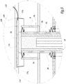
- gasket 34 is extended whereas on the contrary spring 26 is compressed.
- gasket 34 is extended whereas on the contrary spring 26 is compressed.
- gasket and said spring are only shown partially.
- the energy reserve 112 of the vehicle 102 is also electrically in contact with a fixed energy supply station, which is referred to with number 36 in figure 4 .
- This electrical contact takes place successively by means of the wire 22, the contact ring 20, the conductive insert 182, the connection plate 32, the connecting plate 108 and lastly the line 110. In such conditions it is possible to electrically recharge the vehicle's reserve 112.
- the skirt 1142 forms a safety element, as shown in figure 5 . Indeed, said skirt protrudes downwards beyond plate 108 and plate 32. Consequently, anybody coming underneath the vehicle or inserting an object in this space could not come into contact with the conductive elements 32 and 108.
- the invention allows the aforementioned objectives to be reached.
- the invention is particularly advantageous in aesthetic terms as it entirely avoids the need for overhead wires.
- the invention guarantees a reduction of the energy reserve stored on board, as it can be recharged periodically.
- each recharging device is likely to have relatively reduced power and dimensions.
- plate 108 advantageously has considerably larger dimensions than those of the connection plate 32, in both directions of the face of the lower surface S". This allows contact to be guaranteed between these two mechanical elements, no matter how the manoeuvres of the vehicle are dispersed Lastly, we underline that the invention has some remarkable advantages in terms of safety. Indeed, in the piston's retracted position, plate 32 is not supplied with electricity, so that it is not able to electrocute anybody who touches it. Moreover, in the piston's extended position, the skirt 1142 forms a barrier intended to prevent any contact with the electrically conductive elements.
Landscapes
- Engineering & Computer Science (AREA)
- Power Engineering (AREA)
- Mechanical Engineering (AREA)
- Transportation (AREA)
- Electric Propulsion And Braking For Vehicles (AREA)
- Current-Collector Devices For Electrically Propelled Vehicles (AREA)
- Charge And Discharge Circuits For Batteries Or The Like (AREA)
- Arrangement Or Mounting Of Propulsion Units For Vehicles (AREA)
Claims (13)
- Dispositif de recharge d'énergie électrique (2) pour un véhicule industriel ou de transport (2) comprenant :- un caisson (4) adapté pour être enterré dans une route (6) ou dans un obstacle de limitation de vitesse,- un piston mobile (18) réalisé au moins partiellement avec un matériau conducteur, ledit piston mobile (18) étant adapté pour adopter une première position rétractée, dans laquelle il est logé entièrement dans le caisson (4), ainsi qu'une seconde position étendue, dans laquelle il fait saillie verticalement au moins partiellement à l'extérieur dudit caisson (4),- des moyens (20, 22) permettant audit piston mobile (18) d'être relié électriquement à un poste d'alimentation en électricité fixe (36),- ledit piston mobile (18) étant équipé d'un élément de connexion électrique (32) adapté pour venir en contact avec un élément de connexion électrique complémentaire (108) dudit véhicule de transport (102) de sorte à transporter de l'énergie électrique du poste fixe (36) à la direction du véhicule,caractérisé en ce que
ledit élément de connexion (32) est une plaque de connexion, placée sur l'extrémité supérieure du piston mobile (18), lesdits moyens (20, 22) permettant audit piston mobile (18) d'être relié électriquement à un poste d'alimentation d'électricité fixe (36) incluant un anneau de contact (20), ledit piston mobile (18) comprenant une gaine d'isolation externe (183) ainsi qu'une zone conductrice intermédiaire (182) reliée électriquement à l'élément de connexion électrique (32), l'anneau de contact (20) étant distante de la zone conductrice (182) dudit piston mobile (18) dans ladite position rétractée, alors que ledit anneau (20) est en contact avec ladite zone conductrice (182) lorsque le piston mobile (18) est dans ladite position étendue. - Dispositif de recharge selon la revendication 1, caractérisé en ce qu'il comprend des moyens pour le déplacement du mécanisme mobile (18) de sa position rétractée à sa position étendue, particulièrement un cylindre.
- Dispositif de recharge selon la revendication 1 ou 2, caractérisé en ce qu'il comprend des moyens (26) de rappel du mécanisme de mobile (18) dans sa position rétractée, particulièrement un ressort de rappel (26).
- Dispositif de recharge selon la revendication 1, caractérisé en ce que dans la position rétractée, l'anneau de contact (20) porte contre au moins un siège (21) adapté pour limiter la course vers le bas de l'anneau lorsque le mécanisme mobile descend (18) dans sa position rétractée, alors que le ou chaque siège (21) est adapté pour ne pas empêcher la course vers le haut de rappel dudit mécanisme mobile vers sa position étendue.
- Dispositif de recharge selon l'une quelconque des revendications précédentes, caractérisé en ce qu'un carter (10) est placé dans le caisson (4), dans lequel la plupart du mécanisme mobile (18) est logé, au moins dans sa position rétractée, ledit carter (10) définissant avec le caisson (14), un espace intermédiaire (12) pour acheminer la poussière et l'humidité, ledit espace intermédiaire étant en communication avec un trop-plein (14).
- Dispositif de recharge selon les revendications 3 et 5, caractérisé en ce que le carter (10) est doté d'une ouverture (30) pour permettre au mécanisme mobile (18) de passer au travers alors qu'un ressort de rappel (26) s'étend entre un tampon (28) placé sur l'arête de ladite ouverture (30) et un anneau d'isolation (24) placé sur le mécanisme mobile (18).
- Dispositif de recharge selon l'une quelconque des revendications précédentes, caractérisé en ce que le caisson (4) est équipé d'une trappe mobile (8) pour permettre au mécanisme mobile (18) de passer au travers dans sa position étendue.
- Dispositif de recharge selon l'une quelconque des revendications précédentes, caractérisé en ce qu'il comprend des moyens pour reconnaître la présence d'un véhicule (102) au-dessus du dispositif de recharge (2), particulièrement un capteur optique ou un capteur RFID ou équivalent.
- Ensemble comprenant un véhicule industriel ou de transport (102) et un dispositif de recharge d'énergie électrique (2) selon l'une quelconque des revendications précédentes, ledit véhicule (102) comprenant un corps (104) monté sur une roue (106), ledit corps (104) étant équipé d'un élément de connexion électrique complémentaire (108) adapté pour venir en contact électrique avec l'élément de connexion électrique (108) adapté pour venir en contact électrique avec l'élément de connexion électrique (32) du dispositif de recharge (2) lorsque le mécanisme mobile (18) est dans sa position étendue.
- Ensemble selon la revendication 9, caractérisé en ce que l'élément de connexion électrique complémentaire est une plaque conductrice (108) placée sur la surface inférieure (S") du corps de véhicule (104).
- Ensemble selon la revendication 10, caractérisé en ce que la plaque conductrice (108) présente des dimensions qui sont considérablement supérieures à celles de l'élément de connexion électrique (32) du dispositif de recharge (2).
- Ensemble selon l'une quelconque des revendications 9 à 11, caractérisé en ce que le véhicule (102) est équipé d'un mécanisme d'isolation intermédiaire (114) s'étendant entre le corps de véhicule (104) et l'élément de connexion électrique complémentaire (108), ledit mécanisme d'isolation intermédiaire étant équipé d'une jupe (1142) adaptée pour s'étendre vers le bas pour couvrir l'élément de connexion électrique (32) et l'élément de connexion électrique complémentaire (108) lorsque les deux derniers éléments sont en contact l'un avec l'autre.
- Ensemble de recharge électrique comprenant plusieurs dispositifs de recharge (2) selon l'une quelconque des revendications 1 à 8, ledit dispositif de recharge étant placé sur un poste, sur lequel le véhicule industriel ou de transport (102) fait un arrêt.
Priority Applications (2)
| Application Number | Priority Date | Filing Date | Title |
|---|---|---|---|
| EP07116941.1A EP2039557B1 (fr) | 2007-09-21 | 2007-09-21 | Dispositif de recharge d'énergie électrique pour véhicule industriel ou transport, ensemble comportant un tel dispositif et ledit véhicule, et ensemble de recharge comportant plusieurs de ces dispositifs |
| ES07116941.1T ES2635372T3 (es) | 2007-09-21 | 2007-09-21 | Dispositivo de recarga de energía eléctrica para vehículo industrial o de transporte, conjunto que comprende dicho dispositivo y dicho vehículo, y un conjunto de recarga que comprende varios de dichos dispositivos |
Applications Claiming Priority (1)
| Application Number | Priority Date | Filing Date | Title |
|---|---|---|---|
| EP07116941.1A EP2039557B1 (fr) | 2007-09-21 | 2007-09-21 | Dispositif de recharge d'énergie électrique pour véhicule industriel ou transport, ensemble comportant un tel dispositif et ledit véhicule, et ensemble de recharge comportant plusieurs de ces dispositifs |
Publications (2)
| Publication Number | Publication Date |
|---|---|
| EP2039557A1 EP2039557A1 (fr) | 2009-03-25 |
| EP2039557B1 true EP2039557B1 (fr) | 2017-05-24 |
Family
ID=39047634
Family Applications (1)
| Application Number | Title | Priority Date | Filing Date |
|---|---|---|---|
| EP07116941.1A Active EP2039557B1 (fr) | 2007-09-21 | 2007-09-21 | Dispositif de recharge d'énergie électrique pour véhicule industriel ou transport, ensemble comportant un tel dispositif et ledit véhicule, et ensemble de recharge comportant plusieurs de ces dispositifs |
Country Status (2)
| Country | Link |
|---|---|
| EP (1) | EP2039557B1 (fr) |
| ES (1) | ES2635372T3 (fr) |
Cited By (2)
| Publication number | Priority date | Publication date | Assignee | Title |
|---|---|---|---|---|
| US11440420B2 (en) | 2017-06-28 | 2022-09-13 | Trojan Energy Limited | Apparatus and system for connecting electric vehicles to an electrical network and method of use |
| WO2025201619A1 (fr) * | 2024-03-25 | 2025-10-02 | Schunk Transit Systems Gmbh | Appareil de positionnement et système de charge |
Families Citing this family (17)
| Publication number | Priority date | Publication date | Assignee | Title |
|---|---|---|---|---|
| FR2940201B1 (fr) | 2008-12-22 | 2014-04-11 | Delachaux Sa | Systemes et ensemble de connexion pour la charge d'un vehicule electrique |
| GB2471879A (en) * | 2009-07-16 | 2011-01-19 | Damien Smith | Electric Vehicle Charging System |
| BE1019049A3 (fr) * | 2009-11-25 | 2012-02-07 | Roadfour S A | Prise de sol a contact pour vehicule electrique ou hybride rechargeable. |
| DE102015206907A1 (de) * | 2015-04-16 | 2016-10-20 | Volkswagen Aktiengesellschaft | Vorrichtung und Verfahren zum elektrischen Laden eines Fahrzeugs |
| DE102015006310B4 (de) | 2015-05-16 | 2022-01-27 | Audi Ag | Ladevorrichtung zum induktiven Laden eines elektrischen Energiespeichers eines Kraftfahrzeugs und Verfahren zum Betreiben einer Ladevorrichtung |
| DE102016121355B4 (de) * | 2016-11-08 | 2024-02-22 | Easelink Gmbh | Fahrzeugverbindungsvorrichtung sowie Fahrzeugverbindungssystem |
| DE102017115909B4 (de) * | 2017-07-14 | 2024-02-22 | Easelink Gmbh | Verfahren zur Herstellung einer elektrischen Verbindung einer Fahrzeugkontakteinheit, Fahrzeugverbindungsvorrichtung zur elektrischen Verbindung einer Fahrzeugkontakteinheit und Fahrzeug mit einer Fahrzeugverbindungsvorrichtung |
| GB2567629B (en) * | 2017-10-13 | 2022-09-21 | Urban Electric Networks Ltd | Retractable charging station |
| GB2573748B (en) * | 2018-05-08 | 2023-01-04 | Urban Electric Networks Ltd | Electric vehicle charging station |
| IT201800005432A1 (it) * | 2018-05-16 | 2019-11-16 | Sistema di ricarica conduttivo di un veicolo elettrico | |
| IT201800005423A1 (it) * | 2018-05-16 | 2019-11-16 | Sistema di ricarica conduttivo di un veicolo elettrico | |
| DE102018112494B4 (de) * | 2018-05-24 | 2023-03-16 | Schunk Transit Systems Gmbh | Kontaktvorrichtung und Schnellladesystem |
| IT201800006614A1 (it) * | 2018-06-25 | 2019-12-25 | Sistema di ricarica conduttivo di un veicolo elettrico | |
| CN109318739B (zh) * | 2018-07-27 | 2020-03-24 | 南京灵雀智能制造有限公司 | 一种新型地埋式电动汽车充电桩 |
| DE102018009010B4 (de) * | 2018-11-16 | 2024-04-25 | Easelink Gmbh | Unterbodenladeeinheit sowie Fahrzeug mit einer Unterbodenladeeinheit |
| CN110027421A (zh) * | 2019-04-23 | 2019-07-19 | 苏州倍力杰自动化技术有限公司 | 一种在线自动充电智能穿梭车 |
| DE102019007712A1 (de) * | 2019-11-07 | 2021-05-12 | Kostal Automobil Elektrik Gmbh & Co. Kg | System zum konduktiven Laden eines Kraftfahrzeugs |
Citations (2)
| Publication number | Priority date | Publication date | Assignee | Title |
|---|---|---|---|---|
| CH688598A5 (de) * | 1993-10-05 | 1997-11-28 | Ernst Erb | Zapf-Parkplatz fuer Elektromobile. |
| CH688599A5 (de) * | 1993-11-01 | 1997-11-28 | Ernst Erb | Zapf-Platz fuer Elektromobile. |
Family Cites Families (3)
| Publication number | Priority date | Publication date | Assignee | Title |
|---|---|---|---|---|
| GB2185866A (en) * | 1985-12-20 | 1987-07-29 | City Wheels Ltd | Charging battery-powered vehicles |
| EP1061631A1 (fr) * | 1996-01-30 | 2000-12-20 | Sumitomo Wiring Systems, Ltd. | Système de connexion et méthode de connexion pour un véhicule automobile électrique |
| GB2352886A (en) | 1999-07-29 | 2001-02-07 | Adrian Robert Mould | Electric vehicle charging system |
-
2007
- 2007-09-21 EP EP07116941.1A patent/EP2039557B1/fr active Active
- 2007-09-21 ES ES07116941.1T patent/ES2635372T3/es active Active
Patent Citations (2)
| Publication number | Priority date | Publication date | Assignee | Title |
|---|---|---|---|---|
| CH688598A5 (de) * | 1993-10-05 | 1997-11-28 | Ernst Erb | Zapf-Parkplatz fuer Elektromobile. |
| CH688599A5 (de) * | 1993-11-01 | 1997-11-28 | Ernst Erb | Zapf-Platz fuer Elektromobile. |
Cited By (2)
| Publication number | Priority date | Publication date | Assignee | Title |
|---|---|---|---|---|
| US11440420B2 (en) | 2017-06-28 | 2022-09-13 | Trojan Energy Limited | Apparatus and system for connecting electric vehicles to an electrical network and method of use |
| WO2025201619A1 (fr) * | 2024-03-25 | 2025-10-02 | Schunk Transit Systems Gmbh | Appareil de positionnement et système de charge |
Also Published As
| Publication number | Publication date |
|---|---|
| ES2635372T3 (es) | 2017-10-03 |
| EP2039557A1 (fr) | 2009-03-25 |
Similar Documents
| Publication | Publication Date | Title |
|---|---|---|
| EP2039557B1 (fr) | Dispositif de recharge d'énergie électrique pour véhicule industriel ou transport, ensemble comportant un tel dispositif et ledit véhicule, et ensemble de recharge comportant plusieurs de ces dispositifs | |
| AU2015261152B2 (en) | Vehicle charging arrangement | |
| US9327608B2 (en) | Extendable and deformable carrier for a primary coil of a charging system | |
| EP2684733A1 (fr) | Station de charge pour véhicule électrique et son dispositif de charge | |
| US9333866B2 (en) | Charging device and charging method with float-mounted charging unit | |
| EP2885170B1 (fr) | Système et procédé pour un échange de batterie rapide dans des véhicules électriques | |
| KR101614597B1 (ko) | 자동차의 전기 에너지 저장 장치의 비접촉식 충전 | |
| US20160167530A1 (en) | Charging method for an energy accumulator of a vehicle | |
| CN104218635A (zh) | 电动车充电站 | |
| US20110148350A1 (en) | System for Charging a Battery in a Motor Vehicle | |
| US9550426B2 (en) | Current transmission device for charging electrical energy stores of vehicles at overhead charging stations | |
| EP2979917B1 (fr) | Route pour charger un véhicule électrique | |
| US20160339791A1 (en) | Autonomous charging for electric vehicles | |
| CN105162211A (zh) | 用于立体车库的汽车充电装置 | |
| JP2013076316A (ja) | 機械式駐車装置 | |
| US9511459B2 (en) | Automatic system for quick dropping of the battery, integrated to an electrical or hybrid vehicle, and consequences on its maximum loading weight | |
| JP6232958B2 (ja) | 非接触給電システム | |
| CN107554334B (zh) | 一种电能补充系统和方法 | |
| CN217175997U (zh) | 一种公交车立体车库系统 | |
| WO2014035399A1 (fr) | Système de charge extensible et déformable | |
| CN206351641U (zh) | 一种电动车的智能充电装置 | |
| CN217917663U (zh) | 一种随车携带的插头式充电桩 | |
| JP7585848B2 (ja) | 充電設備 | |
| US20240198821A1 (en) | System and method for a conductive charging system | |
| JP2022149514A (ja) | 給電システム |
Legal Events
| Date | Code | Title | Description |
|---|---|---|---|
| PUAI | Public reference made under article 153(3) epc to a published international application that has entered the european phase |
Free format text: ORIGINAL CODE: 0009012 |
|
| AK | Designated contracting states |
Kind code of ref document: A1 Designated state(s): AT BE BG CH CY CZ DE DK EE ES FI FR GB GR HU IE IS IT LI LT LU LV MC MT NL PL PT RO SE SI SK TR |
|
| AX | Request for extension of the european patent |
Extension state: AL BA HR MK RS |
|
| 17P | Request for examination filed |
Effective date: 20090923 |
|
| 17Q | First examination report despatched |
Effective date: 20091104 |
|
| AKX | Designation fees paid |
Designated state(s): AT BE BG CH CY CZ DE DK EE ES FI FR GB GR HU IE IS IT LI LT LU LV MC MT NL PL PT RO SE SI SK TR |
|
| RIC1 | Information provided on ipc code assigned before grant |
Ipc: B60L 11/16 20060101ALI20161025BHEP Ipc: B60L 11/18 20060101AFI20161025BHEP Ipc: B60L 11/00 20060101ALI20161025BHEP Ipc: B60M 7/00 20060101ALI20161025BHEP Ipc: B60L 1/00 20060101ALI20161025BHEP Ipc: B60L 1/02 20060101ALI20161025BHEP |
|
| GRAP | Despatch of communication of intention to grant a patent |
Free format text: ORIGINAL CODE: EPIDOSNIGR1 |
|
| INTG | Intention to grant announced |
Effective date: 20161215 |
|
| GRAS | Grant fee paid |
Free format text: ORIGINAL CODE: EPIDOSNIGR3 |
|
| GRAA | (expected) grant |
Free format text: ORIGINAL CODE: 0009210 |
|
| AK | Designated contracting states |
Kind code of ref document: B1 Designated state(s): AT BE BG CH CY CZ DE DK EE ES FI FR GB GR HU IE IS IT LI LT LU LV MC MT NL PL PT RO SE SI SK TR |
|
| REG | Reference to a national code |
Ref country code: GB Ref legal event code: FG4D |
|
| REG | Reference to a national code |
Ref country code: CH Ref legal event code: EP |
|
| REG | Reference to a national code |
Ref country code: IE Ref legal event code: FG4D |
|
| REG | Reference to a national code |
Ref country code: AT Ref legal event code: REF Ref document number: 895845 Country of ref document: AT Kind code of ref document: T Effective date: 20170615 |
|
| REG | Reference to a national code |
Ref country code: DE Ref legal event code: R096 Ref document number: 602007051104 Country of ref document: DE |
|
| REG | Reference to a national code |
Ref country code: SE Ref legal event code: TRGR |
|
| REG | Reference to a national code |
Ref country code: NL Ref legal event code: FP |
|
| REG | Reference to a national code |
Ref country code: FR Ref legal event code: PLFP Year of fee payment: 11 |
|
| REG | Reference to a national code |
Ref country code: ES Ref legal event code: FG2A Ref document number: 2635372 Country of ref document: ES Kind code of ref document: T3 Effective date: 20171003 |
|
| REG | Reference to a national code |
Ref country code: LT Ref legal event code: MG4D |
|
| REG | Reference to a national code |
Ref country code: AT Ref legal event code: MK05 Ref document number: 895845 Country of ref document: AT Kind code of ref document: T Effective date: 20170524 |
|
| PG25 | Lapsed in a contracting state [announced via postgrant information from national office to epo] |
Ref country code: FI Free format text: LAPSE BECAUSE OF FAILURE TO SUBMIT A TRANSLATION OF THE DESCRIPTION OR TO PAY THE FEE WITHIN THE PRESCRIBED TIME-LIMIT Effective date: 20170524 Ref country code: LT Free format text: LAPSE BECAUSE OF FAILURE TO SUBMIT A TRANSLATION OF THE DESCRIPTION OR TO PAY THE FEE WITHIN THE PRESCRIBED TIME-LIMIT Effective date: 20170524 Ref country code: AT Free format text: LAPSE BECAUSE OF FAILURE TO SUBMIT A TRANSLATION OF THE DESCRIPTION OR TO PAY THE FEE WITHIN THE PRESCRIBED TIME-LIMIT Effective date: 20170524 Ref country code: GR Free format text: LAPSE BECAUSE OF FAILURE TO SUBMIT A TRANSLATION OF THE DESCRIPTION OR TO PAY THE FEE WITHIN THE PRESCRIBED TIME-LIMIT Effective date: 20170825 |
|
| PG25 | Lapsed in a contracting state [announced via postgrant information from national office to epo] |
Ref country code: IS Free format text: LAPSE BECAUSE OF FAILURE TO SUBMIT A TRANSLATION OF THE DESCRIPTION OR TO PAY THE FEE WITHIN THE PRESCRIBED TIME-LIMIT Effective date: 20170924 Ref country code: BG Free format text: LAPSE BECAUSE OF FAILURE TO SUBMIT A TRANSLATION OF THE DESCRIPTION OR TO PAY THE FEE WITHIN THE PRESCRIBED TIME-LIMIT Effective date: 20170824 Ref country code: LV Free format text: LAPSE BECAUSE OF FAILURE TO SUBMIT A TRANSLATION OF THE DESCRIPTION OR TO PAY THE FEE WITHIN THE PRESCRIBED TIME-LIMIT Effective date: 20170524 |
|
| PG25 | Lapsed in a contracting state [announced via postgrant information from national office to epo] |
Ref country code: SK Free format text: LAPSE BECAUSE OF FAILURE TO SUBMIT A TRANSLATION OF THE DESCRIPTION OR TO PAY THE FEE WITHIN THE PRESCRIBED TIME-LIMIT Effective date: 20170524 Ref country code: CZ Free format text: LAPSE BECAUSE OF FAILURE TO SUBMIT A TRANSLATION OF THE DESCRIPTION OR TO PAY THE FEE WITHIN THE PRESCRIBED TIME-LIMIT Effective date: 20170524 Ref country code: RO Free format text: LAPSE BECAUSE OF FAILURE TO SUBMIT A TRANSLATION OF THE DESCRIPTION OR TO PAY THE FEE WITHIN THE PRESCRIBED TIME-LIMIT Effective date: 20170524 Ref country code: DK Free format text: LAPSE BECAUSE OF FAILURE TO SUBMIT A TRANSLATION OF THE DESCRIPTION OR TO PAY THE FEE WITHIN THE PRESCRIBED TIME-LIMIT Effective date: 20170524 Ref country code: EE Free format text: LAPSE BECAUSE OF FAILURE TO SUBMIT A TRANSLATION OF THE DESCRIPTION OR TO PAY THE FEE WITHIN THE PRESCRIBED TIME-LIMIT Effective date: 20170524 |
|
| REG | Reference to a national code |
Ref country code: DE Ref legal event code: R097 Ref document number: 602007051104 Country of ref document: DE |
|
| PG25 | Lapsed in a contracting state [announced via postgrant information from national office to epo] |
Ref country code: PL Free format text: LAPSE BECAUSE OF FAILURE TO SUBMIT A TRANSLATION OF THE DESCRIPTION OR TO PAY THE FEE WITHIN THE PRESCRIBED TIME-LIMIT Effective date: 20170524 |
|
| PLBE | No opposition filed within time limit |
Free format text: ORIGINAL CODE: 0009261 |
|
| STAA | Information on the status of an ep patent application or granted ep patent |
Free format text: STATUS: NO OPPOSITION FILED WITHIN TIME LIMIT |
|
| REG | Reference to a national code |
Ref country code: CH Ref legal event code: PL |
|
| 26N | No opposition filed |
Effective date: 20180227 |
|
| PG25 | Lapsed in a contracting state [announced via postgrant information from national office to epo] |
Ref country code: SI Free format text: LAPSE BECAUSE OF FAILURE TO SUBMIT A TRANSLATION OF THE DESCRIPTION OR TO PAY THE FEE WITHIN THE PRESCRIBED TIME-LIMIT Effective date: 20170524 Ref country code: MC Free format text: LAPSE BECAUSE OF FAILURE TO SUBMIT A TRANSLATION OF THE DESCRIPTION OR TO PAY THE FEE WITHIN THE PRESCRIBED TIME-LIMIT Effective date: 20170524 |
|
| REG | Reference to a national code |
Ref country code: IE Ref legal event code: MM4A |
|
| REG | Reference to a national code |
Ref country code: BE Ref legal event code: MM Effective date: 20170930 |
|
| PG25 | Lapsed in a contracting state [announced via postgrant information from national office to epo] |
Ref country code: LU Free format text: LAPSE BECAUSE OF NON-PAYMENT OF DUE FEES Effective date: 20170921 |
|
| PG25 | Lapsed in a contracting state [announced via postgrant information from national office to epo] |
Ref country code: LI Free format text: LAPSE BECAUSE OF NON-PAYMENT OF DUE FEES Effective date: 20170930 Ref country code: IE Free format text: LAPSE BECAUSE OF NON-PAYMENT OF DUE FEES Effective date: 20170921 Ref country code: CH Free format text: LAPSE BECAUSE OF NON-PAYMENT OF DUE FEES Effective date: 20170930 |
|
| PG25 | Lapsed in a contracting state [announced via postgrant information from national office to epo] |
Ref country code: BE Free format text: LAPSE BECAUSE OF NON-PAYMENT OF DUE FEES Effective date: 20170930 |
|
| PG25 | Lapsed in a contracting state [announced via postgrant information from national office to epo] |
Ref country code: MT Free format text: LAPSE BECAUSE OF NON-PAYMENT OF DUE FEES Effective date: 20170921 |
|
| REG | Reference to a national code |
Ref country code: FR Ref legal event code: PLFP Year of fee payment: 12 |
|
| REG | Reference to a national code |
Ref country code: DE Ref legal event code: R079 Ref document number: 602007051104 Country of ref document: DE Free format text: PREVIOUS MAIN CLASS: B60L0011180000 Ipc: B60L0050500000 |
|
| PG25 | Lapsed in a contracting state [announced via postgrant information from national office to epo] |
Ref country code: HU Free format text: LAPSE BECAUSE OF FAILURE TO SUBMIT A TRANSLATION OF THE DESCRIPTION OR TO PAY THE FEE WITHIN THE PRESCRIBED TIME-LIMIT; INVALID AB INITIO Effective date: 20070921 |
|
| PG25 | Lapsed in a contracting state [announced via postgrant information from national office to epo] |
Ref country code: CY Free format text: LAPSE BECAUSE OF NON-PAYMENT OF DUE FEES Effective date: 20170524 |
|
| PG25 | Lapsed in a contracting state [announced via postgrant information from national office to epo] |
Ref country code: TR Free format text: LAPSE BECAUSE OF FAILURE TO SUBMIT A TRANSLATION OF THE DESCRIPTION OR TO PAY THE FEE WITHIN THE PRESCRIBED TIME-LIMIT Effective date: 20170524 |
|
| PG25 | Lapsed in a contracting state [announced via postgrant information from national office to epo] |
Ref country code: PT Free format text: LAPSE BECAUSE OF FAILURE TO SUBMIT A TRANSLATION OF THE DESCRIPTION OR TO PAY THE FEE WITHIN THE PRESCRIBED TIME-LIMIT Effective date: 20170524 |
|
| PGFP | Annual fee paid to national office [announced via postgrant information from national office to epo] |
Ref country code: SE Payment date: 20220923 Year of fee payment: 16 Ref country code: NL Payment date: 20220926 Year of fee payment: 16 |
|
| REG | Reference to a national code |
Ref country code: NL Ref legal event code: PD Owner name: IVECO FRANCE S.A.S.; FR Free format text: DETAILS ASSIGNMENT: CHANGE OF OWNER(S), CHANGE OF LEGAL ENTITY; FORMER OWNER NAME: IVECO FRANCE S.A. Effective date: 20230406 |
|
| REG | Reference to a national code |
Ref country code: DE Ref legal event code: R081 Ref document number: 602007051104 Country of ref document: DE Owner name: IVECO FRANCE S.A.S., FR Free format text: FORMER OWNER: IVECO FRANCE S.A., VENISSIEUX, FR |
|
| P01 | Opt-out of the competence of the unified patent court (upc) registered |
Effective date: 20230522 |
|
| REG | Reference to a national code |
Ref country code: SE Ref legal event code: EUG |
|
| REG | Reference to a national code |
Ref country code: NL Ref legal event code: MM Effective date: 20231001 |
|
| REG | Reference to a national code |
Ref country code: ES Ref legal event code: PC2A Owner name: IVECO FRANCE S.A.S. Effective date: 20240614 |
|
| PG25 | Lapsed in a contracting state [announced via postgrant information from national office to epo] |
Ref country code: NL Free format text: LAPSE BECAUSE OF NON-PAYMENT OF DUE FEES Effective date: 20231001 |
|
| PG25 | Lapsed in a contracting state [announced via postgrant information from national office to epo] |
Ref country code: NL Free format text: LAPSE BECAUSE OF NON-PAYMENT OF DUE FEES Effective date: 20231001 |
|
| PG25 | Lapsed in a contracting state [announced via postgrant information from national office to epo] |
Ref country code: SE Free format text: LAPSE BECAUSE OF NON-PAYMENT OF DUE FEES Effective date: 20230922 |
|
| PGFP | Annual fee paid to national office [announced via postgrant information from national office to epo] |
Ref country code: DE Payment date: 20240926 Year of fee payment: 18 |
|
| PGFP | Annual fee paid to national office [announced via postgrant information from national office to epo] |
Ref country code: GB Payment date: 20240924 Year of fee payment: 18 |
|
| PGFP | Annual fee paid to national office [announced via postgrant information from national office to epo] |
Ref country code: FR Payment date: 20240925 Year of fee payment: 18 |
|
| PGFP | Annual fee paid to national office [announced via postgrant information from national office to epo] |
Ref country code: IT Payment date: 20240911 Year of fee payment: 18 |
|
| PGFP | Annual fee paid to national office [announced via postgrant information from national office to epo] |
Ref country code: ES Payment date: 20241021 Year of fee payment: 18 |