EP2039821B1 - Knopf-Aufbau für Waschmaschine und Herstellungsverfahren dafür - Google Patents
Knopf-Aufbau für Waschmaschine und Herstellungsverfahren dafür Download PDFInfo
- Publication number
- EP2039821B1 EP2039821B1 EP08015265A EP08015265A EP2039821B1 EP 2039821 B1 EP2039821 B1 EP 2039821B1 EP 08015265 A EP08015265 A EP 08015265A EP 08015265 A EP08015265 A EP 08015265A EP 2039821 B1 EP2039821 B1 EP 2039821B1
- Authority
- EP
- European Patent Office
- Prior art keywords
- knob
- lamp window
- lamp
- guard
- main body
- Prior art date
- Legal status (The legal status is an assumption and is not a legal conclusion. Google has not performed a legal analysis and makes no representation as to the accuracy of the status listed.)
- Not-in-force
Links
- 238000004519 manufacturing process Methods 0.000 title claims abstract description 16
- 229910001220 stainless steel Inorganic materials 0.000 claims description 19
- 239000010935 stainless steel Substances 0.000 claims description 19
- 238000000034 method Methods 0.000 claims description 15
- 230000000149 penetrating effect Effects 0.000 claims description 11
- 238000005323 electroforming Methods 0.000 claims description 6
- 238000001179 sorption measurement Methods 0.000 claims description 4
- 238000005406 washing Methods 0.000 description 19
- 239000002184 metal Substances 0.000 description 9
- 229910052751 metal Inorganic materials 0.000 description 9
- 238000002347 injection Methods 0.000 description 7
- 239000007924 injection Substances 0.000 description 7
- 238000007747 plating Methods 0.000 description 7
- PXHVJJICTQNCMI-UHFFFAOYSA-N Nickel Chemical compound [Ni] PXHVJJICTQNCMI-UHFFFAOYSA-N 0.000 description 6
- -1 preferably Substances 0.000 description 5
- 230000000694 effects Effects 0.000 description 4
- 239000000463 material Substances 0.000 description 4
- 238000000926 separation method Methods 0.000 description 4
- 230000006870 function Effects 0.000 description 3
- 229910052759 nickel Inorganic materials 0.000 description 3
- 239000012780 transparent material Substances 0.000 description 3
- 230000000007 visual effect Effects 0.000 description 3
- 230000005540 biological transmission Effects 0.000 description 2
- NTXGQCSETZTARF-UHFFFAOYSA-N buta-1,3-diene;prop-2-enenitrile Chemical compound C=CC=C.C=CC#N NTXGQCSETZTARF-UHFFFAOYSA-N 0.000 description 2
- 229920006026 co-polymeric resin Polymers 0.000 description 2
- 239000003086 colorant Substances 0.000 description 2
- 238000003780 insertion Methods 0.000 description 2
- 230000037431 insertion Effects 0.000 description 2
- 238000000465 moulding Methods 0.000 description 2
- 238000010009 beating Methods 0.000 description 1
- 230000008878 coupling Effects 0.000 description 1
- 238000010168 coupling process Methods 0.000 description 1
- 238000005859 coupling reaction Methods 0.000 description 1
- 239000003599 detergent Substances 0.000 description 1
- 238000001035 drying Methods 0.000 description 1
- 230000002708 enhancing effect Effects 0.000 description 1
- 238000001746 injection moulding Methods 0.000 description 1
- 238000003698 laser cutting Methods 0.000 description 1
- 238000005259 measurement Methods 0.000 description 1
- 239000000049 pigment Substances 0.000 description 1
- 230000035807 sensation Effects 0.000 description 1
- 239000000758 substrate Substances 0.000 description 1
- XLYOFNOQVPJJNP-UHFFFAOYSA-N water Substances O XLYOFNOQVPJJNP-UHFFFAOYSA-N 0.000 description 1
Images


Classifications
-
- D—TEXTILES; PAPER
- D06—TREATMENT OF TEXTILES OR THE LIKE; LAUNDERING; FLEXIBLE MATERIALS NOT OTHERWISE PROVIDED FOR
- D06F—LAUNDERING, DRYING, IRONING, PRESSING OR FOLDING TEXTILE ARTICLES
- D06F34/00—Details of control systems for washing machines, washer-dryers or laundry dryers
- D06F34/28—Arrangements for program selection, e.g. control panels therefor; Arrangements for indicating program parameters, e.g. the selected program or its progress
- D06F34/30—Arrangements for program selection, e.g. control panels therefor; Arrangements for indicating program parameters, e.g. the selected program or its progress characterised by mechanical features, e.g. buttons or rotary dials
-
- D—TEXTILES; PAPER
- D06—TREATMENT OF TEXTILES OR THE LIKE; LAUNDERING; FLEXIBLE MATERIALS NOT OTHERWISE PROVIDED FOR
- D06F—LAUNDERING, DRYING, IRONING, PRESSING OR FOLDING TEXTILE ARTICLES
- D06F34/00—Details of control systems for washing machines, washer-dryers or laundry dryers
- D06F34/28—Arrangements for program selection, e.g. control panels therefor; Arrangements for indicating program parameters, e.g. the selected program or its progress
-
- D—TEXTILES; PAPER
- D06—TREATMENT OF TEXTILES OR THE LIKE; LAUNDERING; FLEXIBLE MATERIALS NOT OTHERWISE PROVIDED FOR
- D06F—LAUNDERING, DRYING, IRONING, PRESSING OR FOLDING TEXTILE ARTICLES
- D06F37/00—Details specific to washing machines covered by groups D06F21/00 - D06F25/00
- D06F37/26—Casings; Tubs
-
- D—TEXTILES; PAPER
- D06—TREATMENT OF TEXTILES OR THE LIKE; LAUNDERING; FLEXIBLE MATERIALS NOT OTHERWISE PROVIDED FOR
- D06F—LAUNDERING, DRYING, IRONING, PRESSING OR FOLDING TEXTILE ARTICLES
- D06F39/00—Details of washing machines not specific to a single type of machines covered by groups D06F9/00 - D06F27/00
- D06F39/12—Casings; Tubs
-
- F—MECHANICAL ENGINEERING; LIGHTING; HEATING; WEAPONS; BLASTING
- F21—LIGHTING
- F21V—FUNCTIONAL FEATURES OR DETAILS OF LIGHTING DEVICES OR SYSTEMS THEREOF; STRUCTURAL COMBINATIONS OF LIGHTING DEVICES WITH OTHER ARTICLES, NOT OTHERWISE PROVIDED FOR
- F21V33/00—Structural combinations of lighting devices with other articles, not otherwise provided for
- F21V33/0004—Personal or domestic articles
- F21V33/0044—Household appliances, e.g. washing machines or vacuum cleaners
-
- H—ELECTRICITY
- H01—ELECTRIC ELEMENTS
- H01H—ELECTRIC SWITCHES; RELAYS; SELECTORS; EMERGENCY PROTECTIVE DEVICES
- H01H71/00—Details of the protective switches or relays covered by groups H01H73/00 - H01H83/00
- H01H71/10—Operating or release mechanisms
- H01H71/50—Manual reset mechanisms which may be also used for manual release
- H01H71/56—Manual reset mechanisms which may be also used for manual release actuated by rotatable knob or wheel
-
- D—TEXTILES; PAPER
- D06—TREATMENT OF TEXTILES OR THE LIKE; LAUNDERING; FLEXIBLE MATERIALS NOT OTHERWISE PROVIDED FOR
- D06F—LAUNDERING, DRYING, IRONING, PRESSING OR FOLDING TEXTILE ARTICLES
- D06F2105/00—Systems or parameters controlled or affected by the control systems of washing machines, washer-dryers or laundry dryers
- D06F2105/58—Indications or alarms to the control system or to the user
Definitions
- the present invention relates to a laundry machine or washing machine, and particularly, to a knob assembly which is disposed at a control panel and has a dial knob for inputting a washing condition, and a manufacturing method thereof.
- a laundry machine includes a washer (washing machine), a dryer, a refresher and the like.
- a drum-type washing machine operates in a manner of using a frictional force between a drum, which is rotated by a driving force from a motor, and laundry, in a state of containing detergent, water and the laundry in the drum.
- the drum-type washing machine can have a washing effect of beating and rubbing laundry without making the laundry damaged or get tangled, resulting in a recent increase in a demand therefor.
- the drum-type washing machine includes a cabinet configuring an external figure, a tub installed inside the cabinet, and a drum rotating with being accommodated in the tub and containing laundry therein.
- a front cover is mounted at a front surface of the cabinet, and a door for opening/closing an inlet of the drum is mounted at an approximately central portion of the front cover.
- a control panel having a manipulating portion for inputting a washing condition and a display for showing the course of washing or the like is disposed on an upper portion of the front cover.
- a variety of control substrates and electric components are provided inside the control panel.
- the manipulating portion for inputting the washing condition is configured in a shape of button or a type of dial knob rotated by a user to input such washing condition.
- FIG. 1 is an enlarged perspective view showing general dial knob and knob deco mounted in a laundry machine.
- the general dial knob 10 As shown in FIG. 1 , the general dial knob 10 according to the related art is mounted at a central portion or an edge of one side of the control panel.
- the dial knob 10 includes a dial 11 grasped by a user for rotation so as to set a washing condition, and a knob guard 12 fixedly inserted in a control panel 15.
- the knob guard 12 has a front surface configured in an annular shape with a certain width.
- the knob guard 12 is also provided at its front surface with lamp window insertion grooves 14 in which lamp windows 13 are inserted.
- the dial 11 is inserted into the central portion of the knob guard 12 in a direction inserted from a rear surface to a front surface.
- the lamp window insertion grooves 14 are formed to have a certain interval therebetween.
- Several washing conditions are respectively printed on the control panel 15 on an outer circumferential surface of the knob guard 12, at points corresponding to the lamp windows 13. Lamps are mounted at rear surfaces of the lamp windows 13, such that light of the lamps can be emitted through the lamp windows 13.
- a lamp window main body (not shown) on which the lamp windows 13 are disposed is mounted at a rear surface of the knob guard 12.
- the lamp window main body is mounted by being inserted in the rear surface of the knob guard 12.
- a transparent material is vacuum-deposited on the surface of the lamp window main body.
- each of the knob guard 12 and the lamp window main body is typically fabricated by an electroforming molding following by an injection process.
- WO 2007/043819 A1 describes a control unit of a laundry processing apparatus.
- the control unit comprises a backboard, on which a knob switch is mounted, to be operated by a user using a laundry machine.
- the knob switch includes a knob that is rotatably seated at the front of a supported and projects forward from a control panel of the control unit.
- the supporter includes a sliding seating unit formed at the front and having a flunch unit of the knob rotatable seated therein, and an LED support unit circularly disposed outside of the seating unit and configured to support a plurality of LEDs.
- a guide rib for guiding the rotation of the knob projects in a circumference direction with the sliding seating unit.
- the LED supporting unit projects forward around the outer circumferential surface of the sliding seating unit in such way to guide the rotation of the knob in the same manner as the guide rib.
- a plurality of LED holes in which the LEDs for displaying the rotation angle of a decoder are disposed are formed in the LED support unit in the circumference direction with them being spaced apart from each other. The LED holes support the LEDs disposed in the board, and guide light of the LEDs into a desired direction.
- a ring-shaped transparent window through which the light of the LEDs is projected is disposed at the front of the LED support unit.
- a knob assembly includes a knob guard in which a dial knob is inserted, a lamp window main body mounted at a rear surface of the knob guard, and having lamp windows for transmitting light emitted from a rear side of the knob guard to a front side of the knob guard, and lamp window shielding members mounted at the corresponding lamp windows and configured to shield part of light transmitted through the lamp windows.
- the lamp window shielding member is formed of a metal, preferably, stainless steel.
- the main body and the knob assembly can achieve a similar feel of a material and an aesthetic effect.
- the lamp window shielding member is smaller than the lamp window when being seen from the front side of the knob guard. Accordingly, light can be leaked between the lamp window shielding member and the lamp window.
- the lamp window shielding member is configured as a pin which penetrates through the lamp window or as a sheet partially inserted in the lamp window.
- the lamp window shielding member outwardly protrudes further than the lamp window, which thusly enhances a user's tactile sensation.
- slots are further formed between the lamp window main body and the lamp windows.
- a rib protruded from the rear surface of the knob guard is inserted in each slot.
- the rib extends longer than the rear surface of the lamp window main body.
- the knob guard is provided with a plurality of lamp window penetrating holes in which the lamp windows are inserted, and the surface of the knob guard having the lamp window penetrating holes is plated.
- Hair lines are formed on the surface of the knob guard to provide the feel of a metal.
- Separation preventing fringes are radially formed at an edge of a lower end of the knob guard, to avoid the knob guard from being stripped from the laundry machine.
- the knob guard is formed of Acrylonitrile Butadiene Copolymer resin
- the lamp window main body is formed of acryl.
- the use of such materials allows the knob guard and the lamp window main body to be fabricated in an injection manner.
- the lamp window main body is formed of the acryl to maintain its transparency.
- a method for manufacturing a knob assembly includes injecting the knob guard, fixing the lamp window shielding members, and injecting the lamp window main body.
- the step of injecting the knob guard uses an electroforming mold having hair lines formed at its central portion. As such, the use of the mold having the hair lines previously formed can reduce a separate process of generating the hair lines on the knob guard.
- the step of injecting the lamp window main body is injected integrally with the knob guard and the lamp window shielding members.
- a productivity can be improved.
- the step of fixing the lamp window shielding members is configured to fix the lamp window shielding members by using jigs. It is appropriate when the lamp window shielding member is implemented as a pin.
- the step of fixing the lamp window shielding member is configured to fix the lamp window shielding member to a lower or upper side of a mold, which is appropriate when the lamp window shielding member is implemented as a thin sheet.
- the lamp window shielding member is fixed thereto by using a vacuum adsorption or magnet.
- the lamp window shielding member is formed of 400-series stainless steel, which is because the 400-series stainless steel among others is attracted to the magnet.
- a laundry machine includes a dial knob for inputting an operation condition of the laundry machine in a rotational manner, the knob assembly having described above, and a control panel having the dial knob and the knob assembly disposed thereat for allowing the input of the operation condition or a display of a operational state.
- the present invention can fabricate the knob guard and the lamp window main body by the double injection, which results in preventing an inconvenience that the knob guard and the lamp window main body are separately injected to thereafter be assembled with each other, thereby improving a productivity.
- the present invention can also reduce a manufacturing cost of the knob deco by attaching the stainless steel only onto the lamp window portion without having to fabricate the entire knob assembly by using the stainless steel for the harmony of the feel of the stainless steel main body and the knob assembly.
- the present invention can enhance an overall aesthetic effect of the laundry machine having the stainless steel main body by installing the shielding members having the feel of the stainless steel on the lamp windows of the knob assembly.
- FIG. 2 is a front perspective view showing a dial knob and a knob deco or a knob assembly in accordance with one exemplary embodiment of the present invention
- FIG. 3 is a plan view of the knob assembly of FIG. 2 .
- the knob assembly 100 in accordance with one exemplary embodiment of the present invention may include a knob guard 120 having a dial knob 110 inserted therein, a lamp window main body (not shown) disposed at a rear surface of the knob guard 120 and having lamp windows 141 for transmitting light emitted from a rear side of the knob guard 120 to a front side of the knob guard 120, and lamp window shielding members 130 mounted on the corresponding lamp windows 141 for shielding part of light transmitted through the lamp windows 141.
- knob assembly 100 is used in a drum-type washing machine, one of the laundry machine, and the other configuration of the drum-type washing machine excluding the knob assembly 100 is the same to the configuration of the typical drum-type washing machine, description of which will thusly be omitted.
- a separation preventing fringe 121 for preventing the knob assembly 100 from being stripped from the control panel (See 15 of FIG. 1 ) of the laundry machine is formed at an edge of a lower end of the knob guard 120.
- the lamp window shielding member 130 is formed of a metal, so as to be harmonious with the metallic feel of the control panel at which the knob guard 120 is installed. If the control panel 15 having the knob guard 120 is formed of stainless steel, the shielding member 130 is also formed of the stainless steel to be harmonious.
- the surface of the knob guard 120 may have hair lines formed thereon or be applied with a metal plating, thus to be harmonious with the material or the feel of the surface of the control panel 15 at the laundry machine having the knob guard 120. That is, in order to provide the feel of the metal on the surface of the knob guard 120, such hair lines are formed or the metal plating is applied.
- the knob guard 120 may be injected.
- the knob guard 120 is injected by using Acrylonitrile Butadiene Copolymer resin.
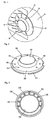
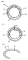
- FIG. 4 is a rear view of a knob guard configuring the knob deco of FIG. 2
- FIG. 5 is a rear view of the knob assembly (100) in a state where the knob guard of FIG. 4 is coupled to a lamp window main body
- FIG. 6 is a perspective view of the lamp window main body of FIG. 5 .
- a mounting portion 125 for mounting the 120 As shown in FIG. 4 and 5 , a mounting portion 125 for mounting the 120.
- the mounting portion 125 is recessed in the circumference of the knob guard 120.
- the mounting portion 125 is provided with a plurality of lamp window penetrating holes 123, and ribs 124 are formed between the lamp window penetrating holes 123.
- the lamp windows 141 of the lamp window main body 140 are disposed through the lamp window penetrating holes 123.
- the rib 124 protrudes through the mounting portion 125.
- the rib 124 preferably extends to be longer than the rear surface of the lamp window main body 140 mounted at the mounting portion 125.
- Such rib 124 can be configured to reduce a permeation of light emitted from each light source (not shown), which is disposed at the rear side of the lamp window 141, into neighboring lamp windows 141 or an interference between light.
- the lamp window main body 140 includes a plurality of lamp windows 141, and slots 142 formed between neighboring lamp windows 141.
- the lamp window main body 140 is preferably formed in a hoof-like shape or an annular shape having one end open.
- the slots 142 are formed by a laser cutting.
- the lamp window main body 140 is formed of a transparent material to allow a transmission of light. Concerning a manufacturing method, it is effective for the lamp window main body 140 to be formed of acryl.
- the lamp window shielding member 130 is disposed on the lamp window 141.
- a coupled state of the lamp window shielding members 130, the lamp windows 141 and lamp window penetrating holes 123 will be described with reference to FIG. 7 .
- FIG. 7 is a cross-sectional view taken along the line - of FIG. 5 .
- the lamp window 141 is smaller than the lamp window penetrating hole 123 of the knob guard 120, and the lamp window shielding member 130 is smaller than the lamp window 141.
- the lamp window main body 140 is formed of transparent acryl, and accordingly light emitted from the light source (not shown) disposed at the rear side of the lamp window main body 140 transmits through the lamp window main body 140, thus to be spread to the front side of the knob guard 120.
- the lamp window shielding member 130 which is smaller than the lamp window 141 is mounted on the lamp window 141, thereby allowing light to be leaked out of the periphery of the lamp window shielding member 130.
- the lamp window shielding member 130 is formed of a metal, the light leaked out of the periphery of the lamp window shielding member 130 is reflected on the lamp window shielding member 130 formed of a metal. Accordingly, the visual effect of the knob assembly 100 can be implemented and also a user can clearly recognize the function of the laundry machine indicated by the dial knob 110.
- the lamp window shielding member 130 preferably protrudes further than the lamp window 141 or to the front side of the knob guard 120 because light can be reflected by using the side surface of the protruded shielding member 130.
- the knob guard 120, the lamp window main body 140 and the lamp window shielding member 130 are almost integrally assembled with each other without being spaced apart.
- a manufacturing method of the knob assembly 100 will be described.
- FIG. 8 is a view showing a procedure of manufacturing the knob assembly (100) in accordance with the one exemplary embodiment of the present invention
- FIG. 9 is a flowchart showing a manufacturing procedure of the knob assembly (100) of FIG. 8 .
- the knob assembly 100 in accordance with the one exemplary embodiment of the present invention can be fabricated by performing the steps of injecting the knob guard 120 (S100), fixing the lamp window shielding members 130 (S200), and injecting the lamp window main body 140 (S300).
- the step (S100) of injecting the knob guard 120 uses an electroforming mold having hair lines formed thereon.
- the electroforming mold is configured with an upper mold and a lower mold.
- the hair lines are formed on the electroforming mold to correspond to the surface having the lamp window penetrating holes 123 of the knob guard 120. Accordingly, a process of forming such hair lines on the surface after the injection of the knob guard 120 cannot separately be performed, resulting in an increase in productivity.
- the hair line literally forms a fine unevenness with a thickness of hair.
- a pitch of the hair line is approximately 0.2 mm, which allows an effective expression of metallic feel.
- the surface of the knob guard 120 may be applied with a nickel plating or the like so as to achieve the feel of the metal.
- nickel plating may be applied after the step (S100) of injecting the knob guard 120 or after the step (S300) of injecting the lamp window main body 140.
- Such nickel plating is applied on the surface having the hair lines, whereas a glossy plating is applied on the surface of the knob guard 120 without having the hair lines.
- step (S200) of fixing the lamp window shielding member 130 is performed by fixing the shielding members 130 using jigs (not shown).
- Other fixing manner may be employed according to the shape of the shielding member 130, which will be described with reference to FIGS. 10a and 10b .
- FIG. 10a is a cross-sectional view showing one example as to how to fix a lamp window shielding member to the knob guard of FIG. 4
- FIG. 10b is a cross-sectional view showing another example as to how to fix the lamp window shielding member to the knob assembly (100) of FIG. 4 .
- a lamp window shielding member 130 is implemented as a pin having a certain length.
- a pin portion 131 having a certain length is fixed to a lower mold 150, thereafter to inject the lamp window main body 140.
- a lamp window shielding member 130 is configured as a plate or sheet which is thin in thickness
- the sheet-like shielding member 130 is partially inserted in the lamp window 141.
- the thickness of the shielding member 130 is 1.0 mm and a diameter thereof is 2.5 mm.
- Such measurement of the shielding member 130 must be determined by concerning the height or diameter of the lamp window penetrating hole 123 or the lamp window 141.
- a vacuum adsorption or magnet is used. That is, an adsorbing unit or a magnet for generating a strong adsorption force or magnetic attraction is disposed at a rear side of the shielding member 130 , thereby to fix the shielding member 130 to the upper mold.
- the lamp window shielding member 130 should be formed of a material which the magnet can attract.
- the lamp window shielding member 130 is formed of stainless steel, a 400-series stainless steel which the magnet can attract should be used.
- the step (S300) of injecting the lamp window main body 140 is followed, thereby finally manufacturing the knob assembly 100.
- the step (S300) of injecting the lamp window main body 140 is performed after the lamp window shielding member 130 is fixed to the knob guard 120. Accordingly, a double injection or bi-injection is performed to integrally implement the knob assembly 100.
- the double injection can avoid the inconvenience that the lamp window main body 140 and the knob guard 120 are separately injected and thereafter assembled with each other.
- pigments with a variety of colors are mixed with the molding of the lamp window main body 140, to obtain various light transmission effects.
- a laundry machine includes a dial knob 110 for allowing an input of an operation condition of the laundry machine, a knob assembly 100 disposed at the periphery of the dial knob 110, and a control panel (See 15 in FIG. 1 ) having the dial knob 110 and the knob assembly 100 disposed thereat and allowing the input of the operation condition or a display of an operational state.
- knob assembly (100) and a manufacturing method thereof can be applied to various types of laundry machine, such as a dryer, a drum-type washing machine compatible with a drying, a combined washing system, a refresher and the like, as well as the drum-type washing machine.
- knob assembly (100) and the manufacturing method thereof may not be limited to the laundry machine formed of stainless steel.
Landscapes
- Engineering & Computer Science (AREA)
- Textile Engineering (AREA)
- General Engineering & Computer Science (AREA)
- Detail Structures Of Washing Machines And Dryers (AREA)
- Main Body Construction Of Washing Machines And Laundry Dryers (AREA)
- Mechanical Control Devices (AREA)
- Switch Cases, Indication, And Locking (AREA)
Claims (15)
- Knopfanordnung (100) einer Waschmaschine, die umfasst:- einen Knopfschirm (120), in den ein Wählknopf (110) eingesetzt ist; und- einen Lampenfenster-Hauptkörper (140), der an einer hinteren Oberfläche des Knopfschirms (120) montiert ist und Lampenfenster (141) besitzt, um Licht, das von einer Rückseite des Knopfschirms (120) emittiert wird, zu einer Vorderseite des Knopfschirms (120) durchzulassen; gekennzeichnet durch:- Lampenfenster-Abschirmelemente (130), die an den entsprechenden Lampenfenstern (141) montiert sind und konfiguriert sind, um Licht, das durch die Lampenfenster (141) durchgelassen wird, teilweise abzuschirmen.
- Knopfanordnung (100) nach Anspruch 1, wobei jedes der Lampenfenster-Abschirmelemente (130) an der vorderen Oberfläche des entsprechenden Lampenfensters (141) angeordnet ist.
- Knopfanordnung (100) nach Anspruch 1, wobei das Lampenfenster-Abschirmelement (130) aus Edelstahl gebildet ist.
- Knopfanordnung (100) nach Anspruch 2, wobei das Lampenfenster-Abschirmelement (130) bei Betrachtung von einer Vorderseite des Knopfschirms (120) kleiner ist als das Lampenfenster (141).
- Knopfanordnung (100) nach Anspruch 1, wobei das Lampenfenster-Abschirmelement (130) als ein Stift konfiguriert ist, der durch das Lampenfenster (141) eindringt.
- Knopfanordnung (100) nach Anspruch 1, wobei das Lampenfenster-Abschirmelement (130) als eine Folie konfiguriert ist, die teilweise in das Lampenfenster (141) eingesetzt ist.
- Knopfanordnung (100) nach Anspruch 1, wobei das Lampenfenster-Abschirmelement (130) weiter als das Lampenfenster (141) nach außen vorsteht.
- Knopfanordnung (100) nach Anspruch 1, wobei der Knopfschirm (120) mit mehreren Lampenfenster-Eindringlöchern (131) versehen ist, in die die Lampenfenster (141) eingesetzt sind,
wobei die Oberfläche des Knopfschirms (120), die die mehreren Lampenfenster-Eindringlöcher (123) aufweist, plattiert ist. - Knopfanordnung (100) nach Anspruch 8, wobei die Oberfläche des Knopfschirms (120) Haarlinien besitzt.
- Verfahren zum Herstellen einer Knopfanordnung (100) einer Waschmaschine, die einen Knopfschirm (120), in den ein Wählknopf (110) eingesetzt ist, und einen Lampenfenster-Hauptkörper (140), der an einer hinteren Oberfläche des Knopfschirms (120) montiert ist, aufweist und Lampenfenster (141) besitzt, um Licht, das von einer Rückseite des Knopfschirms (120) emittiert wird, zu einer Vorderseite des Knopfschirms (120) durchzulassen, gekennzeichnet durch Lampenfenster-Abschirmelemente (130), die an den entsprechenden Lampenfenstern (141) montiert sind und konfiguriert sind, um Licht, das durch die Lampenfenster (141) durchgelassen wird, teilweise abzuschirmen, wobei das Verfahren umfasst:- Spritzgießen des Knopfschirms (120);- Befestigen der Lampenfenster-Abschirmelemente (130); und- Spritzgießen des Lampenfenster-Hauptkörpers (140).
- Verfahren nach Anspruch 10, wobei der Schritt des Spritzgießens des Knopfschirms (120) eine Elektroformungs-Form verwendet, auf der Haarlinien ausgebildet sind.
- Verfahren nach Anspruch 10, wobei der Schritt des Spritzgießens des Lampenfenster-Hauptkörpers (140) ausgeführt wird, nachdem die Lampenfenster-Abschirmelemente (130) an dem Knopfschirm (120) befestigt worden sind.
- Verfahren nach Anspruch 10, wobei der Schritt des Befestigens der Lampenfenster-Abschirmelemente (130) konfiguriert ist, um die Lampenfenster-Abschirmelemente (130) unter Verwendung von Einspannmitteln zu befestigen.
- Verfahren nach Anspruch 10, wobei der Schritt des Befestigens der Lampenfenster-Abschirmelemente (130) konfiguriert ist, um die Lampenfenster-Abschirmelemente an einer unteren oder oberen Seite einer Gießform zu befestigen.
- Verfahren nach Anspruch 14, wobei die Lampenfenster-Abschirmelemente (130) durch Unterdruckadsorption oder unter Verwendung von Magneten befestigt werden, falls die Lampenfenster-Abschirmelemente an der Oberseite der Gießform befestigt werden.
Applications Claiming Priority (1)
| Application Number | Priority Date | Filing Date | Title |
|---|---|---|---|
| KR1020070089179A KR20090024007A (ko) | 2007-09-03 | 2007-09-03 | 노브 데코, 그 제조 방법 및 이를 구비한 의류처리장치 |
Publications (2)
| Publication Number | Publication Date |
|---|---|
| EP2039821A1 EP2039821A1 (de) | 2009-03-25 |
| EP2039821B1 true EP2039821B1 (de) | 2011-06-22 |
Family
ID=40303522
Family Applications (1)
| Application Number | Title | Priority Date | Filing Date |
|---|---|---|---|
| EP08015265A Not-in-force EP2039821B1 (de) | 2007-09-03 | 2008-08-29 | Knopf-Aufbau für Waschmaschine und Herstellungsverfahren dafür |
Country Status (6)
| Country | Link |
|---|---|
| US (1) | US7878669B2 (de) |
| EP (1) | EP2039821B1 (de) |
| KR (1) | KR20090024007A (de) |
| CN (1) | CN101381944B (de) |
| AT (1) | ATE513944T1 (de) |
| ES (1) | ES2365949T3 (de) |
Families Citing this family (10)
| Publication number | Priority date | Publication date | Assignee | Title |
|---|---|---|---|---|
| EP2260751A1 (de) * | 2009-06-10 | 2010-12-15 | Electrolux Home Products Corporation N.V. | Haushaltsgerät |
| DE102010031405A1 (de) * | 2010-07-15 | 2012-01-19 | E.G.O. Elektro-Gerätebau GmbH | Haltevorrichtung für eine Bedieneinrichtung |
| DE102012220255B4 (de) | 2012-11-07 | 2024-04-25 | BSH Hausgeräte GmbH | Haushaltsgerät mit einer Frontblende mit einem Wählbereich und einem Displaybereich |
| KR102133188B1 (ko) * | 2014-04-17 | 2020-07-13 | 엘지전자 주식회사 | 의류처리기기 |
| KR102133189B1 (ko) * | 2014-04-21 | 2020-07-13 | 엘지전자 주식회사 | 의류처리기기 |
| DE102014211305A1 (de) | 2014-06-13 | 2015-12-17 | BSH Hausgeräte GmbH | Haushaltsgerät mit einem Drehschalter und Verfahren zu seinem Betrieb |
| EP3168356B2 (de) | 2015-11-16 | 2023-08-16 | Electrolux Appliances Aktiebolag | Haushaltsgerät mit einem drehbaren benutzerschnittstellenelement |
| DE102016210171A1 (de) | 2016-06-09 | 2017-12-14 | BSH Hausgeräte GmbH | Haushaltsgerät mit beleuchtetem Drehwähler und Verfahren zum Betrieb des Haushaltsgerätes |
| DE102016211327A1 (de) | 2016-06-24 | 2017-12-28 | BSH Hausgeräte GmbH | Haushaltsgerät mit verbessertem Drehwähler und Verfahren zum Betrieb des Haushaltsgerätes |
| DE102016214642B4 (de) | 2016-08-08 | 2024-02-29 | BSH Hausgeräte GmbH | Haushaltsgerät mit Touchdrehwähler, Verfahren zu seiner Herstellung und Verfahren zu seinem Betrieb |
Family Cites Families (9)
| Publication number | Priority date | Publication date | Assignee | Title |
|---|---|---|---|---|
| JP2004227855A (ja) * | 2003-01-21 | 2004-08-12 | Alps Electric Co Ltd | 回転操作型電気部品の照光機構 |
| KR101125389B1 (ko) * | 2004-06-30 | 2012-03-27 | 엘지전자 주식회사 | 드럼 세탁기의 다이얼 놉 구조 및 그 제조 방법 |
| KR101108042B1 (ko) | 2004-07-21 | 2012-01-25 | 엘지전자 주식회사 | 세탁기용 버튼 및 그 제조방법 |
| KR20060085811A (ko) * | 2005-01-25 | 2006-07-28 | 엘지전자 주식회사 | 드럼세탁기 컨트롤패널 어셈블리의 노브 장착구조 |
| KR101203550B1 (ko) * | 2005-05-23 | 2012-11-21 | 엘지전자 주식회사 | 컨트롤 패널 어셈블리 |
| CN1888226A (zh) | 2005-06-29 | 2007-01-03 | 乐金电子(天津)电器有限公司 | 滚筒洗衣机的转盘旋钮结构及其制作方法 |
| CN1888240A (zh) | 2005-06-30 | 2007-01-03 | 乐金电子(天津)电器有限公司 | 洗衣机用按钮及其制作方法 |
| EP1934393B1 (de) | 2005-10-12 | 2017-04-26 | LG Electronics Inc. | Steuereinheit für wäscheverarbeitende vorrichtung |
| KR101285377B1 (ko) * | 2006-09-07 | 2013-07-10 | 엘지전자 주식회사 | 세탁장치용 컨트롤 패널 어셈블리 |
-
2007
- 2007-09-03 KR KR1020070089179A patent/KR20090024007A/ko not_active Ceased
-
2008
- 2008-08-29 EP EP08015265A patent/EP2039821B1/de not_active Not-in-force
- 2008-08-29 AT AT08015265T patent/ATE513944T1/de not_active IP Right Cessation
- 2008-08-29 ES ES08015265T patent/ES2365949T3/es active Active
- 2008-09-02 US US12/202,783 patent/US7878669B2/en not_active Expired - Fee Related
- 2008-09-03 CN CN2008102151532A patent/CN101381944B/zh not_active Expired - Fee Related
Also Published As
| Publication number | Publication date |
|---|---|
| US7878669B2 (en) | 2011-02-01 |
| ATE513944T1 (de) | 2011-07-15 |
| ES2365949T3 (es) | 2011-10-13 |
| CN101381944A (zh) | 2009-03-11 |
| US20090059561A1 (en) | 2009-03-05 |
| CN101381944B (zh) | 2012-06-06 |
| KR20090024007A (ko) | 2009-03-06 |
| EP2039821A1 (de) | 2009-03-25 |
Similar Documents
| Publication | Publication Date | Title |
|---|---|---|
| EP2039821B1 (de) | Knopf-Aufbau für Waschmaschine und Herstellungsverfahren dafür | |
| KR101704418B1 (ko) | 컨트롤 패널 어셈블리 및 이를 포함하는 세탁기 | |
| JP5091113B2 (ja) | 洗浄装置と洗浄装置の作製方法及び組立方法 | |
| EP3561172B1 (de) | Wäschebehandlungsvorrichtung mit einer tür | |
| US8752405B2 (en) | Washing machine and control panel assembly thereof | |
| US8049124B2 (en) | Button for control panel assembly and clothes handling apparatus having the same | |
| EP2471990B1 (de) | Waschmaschine | |
| US7135650B2 (en) | Control panel assembly and method of manufacturing for the same | |
| JP2010063522A (ja) | ドラム式洗濯機 | |
| KR20050086199A (ko) | 세탁기의 컨트롤 장치 | |
| US8179697B2 (en) | Control panel assembly and washing machine having the same | |
| JP4761983B2 (ja) | ドラム式洗濯機 | |
| JP2009213804A (ja) | ドラム式洗濯機 | |
| WO2006001617A1 (en) | Drum type washing machine | |
| EP2034080B1 (de) | Steuertafel-Fensteranordnung für Waschmaschine/Wäschetrockner | |
| CN111519408B (zh) | 衣物处理装置 | |
| US20050178166A1 (en) | Button assembly for electric home appliance and control panel assembly using the same | |
| KR100463517B1 (ko) | 드럼세탁기에 있어서의 컨트롤패널의 버튼 조립구조 | |
| CN100532687C (zh) | 滚桶洗衣机的按钮装饰设置结构 | |
| KR101227478B1 (ko) | 세탁 장치 | |
| CN111394953B (zh) | 一种衣物处理装置 | |
| KR101227476B1 (ko) | 컨트롤 패널의 pcb 어셈블리 | |
| KR20040011973A (ko) | 세탁기의 컨트롤패널과 기판 조립구조 |
Legal Events
| Date | Code | Title | Description |
|---|---|---|---|
| PUAI | Public reference made under article 153(3) epc to a published international application that has entered the european phase |
Free format text: ORIGINAL CODE: 0009012 |
|
| AK | Designated contracting states |
Kind code of ref document: A1 Designated state(s): AT BE BG CH CY CZ DE DK EE ES FI FR GB GR HR HU IE IS IT LI LT LU LV MC MT NL NO PL PT RO SE SI SK TR |
|
| AX | Request for extension of the european patent |
Extension state: AL BA MK RS |
|
| 17P | Request for examination filed |
Effective date: 20090729 |
|
| R17P | Request for examination filed (corrected) |
Effective date: 20090729 |
|
| 17Q | First examination report despatched |
Effective date: 20090827 |
|
| AKX | Designation fees paid |
Designated state(s): AT BE BG CH CY CZ DE DK EE ES FI FR GB GR HR HU IE IS IT LI LT LU LV MC MT NL NO PL PT RO SE SI SK TR |
|
| GRAP | Despatch of communication of intention to grant a patent |
Free format text: ORIGINAL CODE: EPIDOSNIGR1 |
|
| GRAS | Grant fee paid |
Free format text: ORIGINAL CODE: EPIDOSNIGR3 |
|
| GRAA | (expected) grant |
Free format text: ORIGINAL CODE: 0009210 |
|
| AK | Designated contracting states |
Kind code of ref document: B1 Designated state(s): AT BE BG CH CY CZ DE DK EE ES FI FR GB GR HR HU IE IS IT LI LT LU LV MC MT NL NO PL PT RO SE SI SK TR |
|
| REG | Reference to a national code |
Ref country code: GB Ref legal event code: FG4D |
|
| REG | Reference to a national code |
Ref country code: CH Ref legal event code: EP |
|
| REG | Reference to a national code |
Ref country code: IE Ref legal event code: FG4D |
|
| REG | Reference to a national code |
Ref country code: DE Ref legal event code: R096 Ref document number: 602008007727 Country of ref document: DE Effective date: 20110804 |
|
| REG | Reference to a national code |
Ref country code: NL Ref legal event code: VDEP Effective date: 20110622 |
|
| REG | Reference to a national code |
Ref country code: ES Ref legal event code: FG2A Ref document number: 2365949 Country of ref document: ES Kind code of ref document: T3 Effective date: 20111013 |
|
| PG25 | Lapsed in a contracting state [announced via postgrant information from national office to epo] |
Ref country code: SE Free format text: LAPSE BECAUSE OF FAILURE TO SUBMIT A TRANSLATION OF THE DESCRIPTION OR TO PAY THE FEE WITHIN THE PRESCRIBED TIME-LIMIT Effective date: 20110622 Ref country code: HR Free format text: LAPSE BECAUSE OF FAILURE TO SUBMIT A TRANSLATION OF THE DESCRIPTION OR TO PAY THE FEE WITHIN THE PRESCRIBED TIME-LIMIT Effective date: 20110622 Ref country code: LT Free format text: LAPSE BECAUSE OF FAILURE TO SUBMIT A TRANSLATION OF THE DESCRIPTION OR TO PAY THE FEE WITHIN THE PRESCRIBED TIME-LIMIT Effective date: 20110622 Ref country code: NO Free format text: LAPSE BECAUSE OF FAILURE TO SUBMIT A TRANSLATION OF THE DESCRIPTION OR TO PAY THE FEE WITHIN THE PRESCRIBED TIME-LIMIT Effective date: 20110922 |
|
| PG25 | Lapsed in a contracting state [announced via postgrant information from national office to epo] |
Ref country code: AT Free format text: LAPSE BECAUSE OF FAILURE TO SUBMIT A TRANSLATION OF THE DESCRIPTION OR TO PAY THE FEE WITHIN THE PRESCRIBED TIME-LIMIT Effective date: 20110622 Ref country code: SI Free format text: LAPSE BECAUSE OF FAILURE TO SUBMIT A TRANSLATION OF THE DESCRIPTION OR TO PAY THE FEE WITHIN THE PRESCRIBED TIME-LIMIT Effective date: 20110622 Ref country code: GR Free format text: LAPSE BECAUSE OF FAILURE TO SUBMIT A TRANSLATION OF THE DESCRIPTION OR TO PAY THE FEE WITHIN THE PRESCRIBED TIME-LIMIT Effective date: 20110923 Ref country code: LV Free format text: LAPSE BECAUSE OF FAILURE TO SUBMIT A TRANSLATION OF THE DESCRIPTION OR TO PAY THE FEE WITHIN THE PRESCRIBED TIME-LIMIT Effective date: 20110622 Ref country code: CY Free format text: LAPSE BECAUSE OF FAILURE TO SUBMIT A TRANSLATION OF THE DESCRIPTION OR TO PAY THE FEE WITHIN THE PRESCRIBED TIME-LIMIT Effective date: 20110622 Ref country code: FI Free format text: LAPSE BECAUSE OF FAILURE TO SUBMIT A TRANSLATION OF THE DESCRIPTION OR TO PAY THE FEE WITHIN THE PRESCRIBED TIME-LIMIT Effective date: 20110622 |
|
| PG25 | Lapsed in a contracting state [announced via postgrant information from national office to epo] |
Ref country code: NL Free format text: LAPSE BECAUSE OF FAILURE TO SUBMIT A TRANSLATION OF THE DESCRIPTION OR TO PAY THE FEE WITHIN THE PRESCRIBED TIME-LIMIT Effective date: 20110622 Ref country code: BE Free format text: LAPSE BECAUSE OF FAILURE TO SUBMIT A TRANSLATION OF THE DESCRIPTION OR TO PAY THE FEE WITHIN THE PRESCRIBED TIME-LIMIT Effective date: 20110622 Ref country code: MT Free format text: LAPSE BECAUSE OF FAILURE TO SUBMIT A TRANSLATION OF THE DESCRIPTION OR TO PAY THE FEE WITHIN THE PRESCRIBED TIME-LIMIT Effective date: 20110622 |
|
| PG25 | Lapsed in a contracting state [announced via postgrant information from national office to epo] |
Ref country code: CZ Free format text: LAPSE BECAUSE OF FAILURE TO SUBMIT A TRANSLATION OF THE DESCRIPTION OR TO PAY THE FEE WITHIN THE PRESCRIBED TIME-LIMIT Effective date: 20110622 Ref country code: IS Free format text: LAPSE BECAUSE OF FAILURE TO SUBMIT A TRANSLATION OF THE DESCRIPTION OR TO PAY THE FEE WITHIN THE PRESCRIBED TIME-LIMIT Effective date: 20111022 Ref country code: EE Free format text: LAPSE BECAUSE OF FAILURE TO SUBMIT A TRANSLATION OF THE DESCRIPTION OR TO PAY THE FEE WITHIN THE PRESCRIBED TIME-LIMIT Effective date: 20110622 Ref country code: PT Free format text: LAPSE BECAUSE OF FAILURE TO SUBMIT A TRANSLATION OF THE DESCRIPTION OR TO PAY THE FEE WITHIN THE PRESCRIBED TIME-LIMIT Effective date: 20111024 |
|
| PG25 | Lapsed in a contracting state [announced via postgrant information from national office to epo] |
Ref country code: SK Free format text: LAPSE BECAUSE OF FAILURE TO SUBMIT A TRANSLATION OF THE DESCRIPTION OR TO PAY THE FEE WITHIN THE PRESCRIBED TIME-LIMIT Effective date: 20110622 Ref country code: RO Free format text: LAPSE BECAUSE OF FAILURE TO SUBMIT A TRANSLATION OF THE DESCRIPTION OR TO PAY THE FEE WITHIN THE PRESCRIBED TIME-LIMIT Effective date: 20110622 Ref country code: PL Free format text: LAPSE BECAUSE OF FAILURE TO SUBMIT A TRANSLATION OF THE DESCRIPTION OR TO PAY THE FEE WITHIN THE PRESCRIBED TIME-LIMIT Effective date: 20110622 |
|
| PG25 | Lapsed in a contracting state [announced via postgrant information from national office to epo] |
Ref country code: MC Free format text: LAPSE BECAUSE OF NON-PAYMENT OF DUE FEES Effective date: 20110831 |
|
| PLBE | No opposition filed within time limit |
Free format text: ORIGINAL CODE: 0009261 |
|
| STAA | Information on the status of an ep patent application or granted ep patent |
Free format text: STATUS: NO OPPOSITION FILED WITHIN TIME LIMIT |
|
| REG | Reference to a national code |
Ref country code: IE Ref legal event code: MM4A |
|
| 26N | No opposition filed |
Effective date: 20120323 |
|
| PG25 | Lapsed in a contracting state [announced via postgrant information from national office to epo] |
Ref country code: DK Free format text: LAPSE BECAUSE OF FAILURE TO SUBMIT A TRANSLATION OF THE DESCRIPTION OR TO PAY THE FEE WITHIN THE PRESCRIBED TIME-LIMIT Effective date: 20110622 |
|
| REG | Reference to a national code |
Ref country code: DE Ref legal event code: R097 Ref document number: 602008007727 Country of ref document: DE Effective date: 20120323 |
|
| PG25 | Lapsed in a contracting state [announced via postgrant information from national office to epo] |
Ref country code: IE Free format text: LAPSE BECAUSE OF NON-PAYMENT OF DUE FEES Effective date: 20110829 |
|
| REG | Reference to a national code |
Ref country code: CH Ref legal event code: PL |
|
| PG25 | Lapsed in a contracting state [announced via postgrant information from national office to epo] |
Ref country code: CH Free format text: LAPSE BECAUSE OF NON-PAYMENT OF DUE FEES Effective date: 20120831 Ref country code: LI Free format text: LAPSE BECAUSE OF NON-PAYMENT OF DUE FEES Effective date: 20120831 |
|
| PG25 | Lapsed in a contracting state [announced via postgrant information from national office to epo] |
Ref country code: LU Free format text: LAPSE BECAUSE OF NON-PAYMENT OF DUE FEES Effective date: 20110829 |
|
| PG25 | Lapsed in a contracting state [announced via postgrant information from national office to epo] |
Ref country code: BG Free format text: LAPSE BECAUSE OF FAILURE TO SUBMIT A TRANSLATION OF THE DESCRIPTION OR TO PAY THE FEE WITHIN THE PRESCRIBED TIME-LIMIT Effective date: 20110922 |
|
| PG25 | Lapsed in a contracting state [announced via postgrant information from national office to epo] |
Ref country code: TR Free format text: LAPSE BECAUSE OF FAILURE TO SUBMIT A TRANSLATION OF THE DESCRIPTION OR TO PAY THE FEE WITHIN THE PRESCRIBED TIME-LIMIT Effective date: 20110622 |
|
| PG25 | Lapsed in a contracting state [announced via postgrant information from national office to epo] |
Ref country code: HU Free format text: LAPSE BECAUSE OF FAILURE TO SUBMIT A TRANSLATION OF THE DESCRIPTION OR TO PAY THE FEE WITHIN THE PRESCRIBED TIME-LIMIT Effective date: 20110622 |
|
| REG | Reference to a national code |
Ref country code: FR Ref legal event code: PLFP Year of fee payment: 9 |
|
| PGFP | Annual fee paid to national office [announced via postgrant information from national office to epo] |
Ref country code: GB Payment date: 20160707 Year of fee payment: 9 Ref country code: DE Payment date: 20160706 Year of fee payment: 9 Ref country code: IT Payment date: 20160818 Year of fee payment: 9 |
|
| PGFP | Annual fee paid to national office [announced via postgrant information from national office to epo] |
Ref country code: FR Payment date: 20160708 Year of fee payment: 9 |
|
| PGFP | Annual fee paid to national office [announced via postgrant information from national office to epo] |
Ref country code: ES Payment date: 20160711 Year of fee payment: 9 |
|
| REG | Reference to a national code |
Ref country code: DE Ref legal event code: R119 Ref document number: 602008007727 Country of ref document: DE |
|
| GBPC | Gb: european patent ceased through non-payment of renewal fee |
Effective date: 20170829 |
|
| REG | Reference to a national code |
Ref country code: FR Ref legal event code: ST Effective date: 20180430 |
|
| PG25 | Lapsed in a contracting state [announced via postgrant information from national office to epo] |
Ref country code: DE Free format text: LAPSE BECAUSE OF NON-PAYMENT OF DUE FEES Effective date: 20180301 Ref country code: GB Free format text: LAPSE BECAUSE OF NON-PAYMENT OF DUE FEES Effective date: 20170829 |
|
| PG25 | Lapsed in a contracting state [announced via postgrant information from national office to epo] |
Ref country code: IT Free format text: LAPSE BECAUSE OF NON-PAYMENT OF DUE FEES Effective date: 20170829 Ref country code: FR Free format text: LAPSE BECAUSE OF NON-PAYMENT OF DUE FEES Effective date: 20170831 |
|
| REG | Reference to a national code |
Ref country code: ES Ref legal event code: FD2A Effective date: 20181025 |
|
| PG25 | Lapsed in a contracting state [announced via postgrant information from national office to epo] |
Ref country code: ES Free format text: LAPSE BECAUSE OF NON-PAYMENT OF DUE FEES Effective date: 20170830 |