EP2039954A2 - Kappenförmige Tellerfeder-Klemmsysteme - Google Patents
Kappenförmige Tellerfeder-Klemmsysteme Download PDFInfo
- Publication number
- EP2039954A2 EP2039954A2 EP08164536A EP08164536A EP2039954A2 EP 2039954 A2 EP2039954 A2 EP 2039954A2 EP 08164536 A EP08164536 A EP 08164536A EP 08164536 A EP08164536 A EP 08164536A EP 2039954 A2 EP2039954 A2 EP 2039954A2
- Authority
- EP
- European Patent Office
- Prior art keywords
- washer
- cover
- spring washer
- hardware
- package
- Prior art date
- Legal status (The legal status is an assumption and is not a legal conclusion. Google has not performed a legal analysis and makes no representation as to the accuracy of the status listed.)
- Withdrawn
Links
- 230000035939 shock Effects 0.000 claims abstract description 7
- 238000000034 method Methods 0.000 claims abstract description 6
- 229910000831 Steel Inorganic materials 0.000 claims 1
- 230000036316 preload Effects 0.000 claims 1
- 239000010959 steel Substances 0.000 claims 1
- 239000000463 material Substances 0.000 description 7
- 239000002131 composite material Substances 0.000 description 1
- 238000002955 isolation Methods 0.000 description 1
- 229910001220 stainless steel Inorganic materials 0.000 description 1
- 239000010935 stainless steel Substances 0.000 description 1
Images

Classifications
-
- F—MECHANICAL ENGINEERING; LIGHTING; HEATING; WEAPONS; BLASTING
- F16—ENGINEERING ELEMENTS AND UNITS; GENERAL MEASURES FOR PRODUCING AND MAINTAINING EFFECTIVE FUNCTIONING OF MACHINES OR INSTALLATIONS; THERMAL INSULATION IN GENERAL
- F16F—SPRINGS; SHOCK-ABSORBERS; MEANS FOR DAMPING VIBRATION
- F16F15/00—Suppression of vibrations in systems; Means or arrangements for avoiding or reducing out-of-balance forces, e.g. due to motion
- F16F15/02—Suppression of vibrations of non-rotating, e.g. reciprocating systems; Suppression of vibrations of rotating systems by use of members not moving with the rotating systems
- F16F15/04—Suppression of vibrations of non-rotating, e.g. reciprocating systems; Suppression of vibrations of rotating systems by use of members not moving with the rotating systems using elastic means
- F16F15/06—Suppression of vibrations of non-rotating, e.g. reciprocating systems; Suppression of vibrations of rotating systems by use of members not moving with the rotating systems using elastic means with metal springs
-
- F—MECHANICAL ENGINEERING; LIGHTING; HEATING; WEAPONS; BLASTING
- F16—ENGINEERING ELEMENTS AND UNITS; GENERAL MEASURES FOR PRODUCING AND MAINTAINING EFFECTIVE FUNCTIONING OF MACHINES OR INSTALLATIONS; THERMAL INSULATION IN GENERAL
- F16F—SPRINGS; SHOCK-ABSORBERS; MEANS FOR DAMPING VIBRATION
- F16F1/00—Springs
- F16F1/02—Springs made of steel or other material having low internal friction; Wound, torsion, leaf, cup, ring or the like springs, the material of the spring not being relevant
- F16F1/32—Belleville-type springs
Definitions
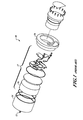
- FIGURE 1 is an exploded view of a portion of a prior art system.
- threaded fasteners ranging from a single large-diameter threaded member ( FIG. 1 ) to multiple #2 or #4 threaded fasteners, attach a cover to an assembly to provide -1200 lbs of clamping load to the assembly.
- the threaded fasteners have an effective spring constant approaching infinity, and so undesirably transmit high frequency vibration to the assembly.
- bulky external shock resistant devices are used, thereby increasing the size of the entire package.
- the present invention provides systems and methods for protecting a hardware device from shock loads in a package.
- An embodiment of a system of the present invention uses a cupped spring washer (or Belleville washer) to apply required clamping loads to internal hardware of a package to meet high g environments while minimizing a total size of the package.
- Embodiments also apply proper clamping loads over a large range of deflection of the internal hardware without placing tolerancing constraints on the overall external package size.
- the benefits of embodiments of the system can include: 1) no additional printed wiring board area (except for the mounting surface); 2) adequate clamping over a large range of deflection and tolerance (self-adjusts); 3) no significant loss of clamping load due to temperature, time, or other environments; 4) high frequency shock attenuation; 5) very low cost and high reliability compared to threaded fasteners; 6) extremely gun hard friendly while maintaining clamping load before, during, and after gun launch.
- Embodiments of the system provides adequate clamping load over a large range of deflection and require only minimal amounts of volume. Embodiments require no additional volume since the system self-adjusts for minimum and maximum material conditions. Also, since embodiments of the invention are truly springs, the supported hardware is more isolated from high frequency shock typically associated with set-forward pulse in high-g launch environments than with threaded fasteners.
- FIGURE 1 is an exploded view of a system according to the prior art
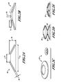
- FIGURE 2A is a side cross-sectional view of an unloaded cupped spring washer according to an embodiment of the present invention
- FIGURE 2B is a side cross-sectional view of the cupped spring washer of FIGURE 2A with a load applied to the washer;
- FIGURE 2C is a perspective view of two embodiments of a cupped spring washer
- FIGURES 2D and 2E show multiple cupped spring washers placed end-to-end and stacked, respectively;
- FIGURE 3A is an exploded view of an embodiment of a system according to the present invention.
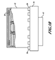
- FIGURE 3B is a side cross-section of the embodiment of FIGURE 3A .
- FIGURES 2A, 2B, and 2C An embodiment of a cupped spring (or Belleville) washer 20 is shown in FIGURES 2A, 2B, and 2C .
- the washer 20 includes an inner diameter 22 and an outer diameter 24, a thickness 26, and an unloaded height 28.
- There is a wide range of materials from which to make the washer including stainless steel, composites, and various other materials known to those having ordinary skill in the art.
- the dimensions of the washer 20 as well as the material used to make the washer are determined by an intended use of the washer and a desired spring constant, including an expected maximum load 30 and a maximum deflection 32.
- the washer 20 can include more than one washer 20, and the washers 20 can be placed end-to-end as shown in FIGURE 2D or stacked as shown in FIGURE 2E .
- FIGURES 3A and 3B are an exploded view and a cross-sectional view, respectively, of an example system 40.
- the system 40 includes a cylindrical cover 42 with one orifice 44 with a perimeter flange 46 including holes 48, which can be threaded, for fasteners 50.
- the cupped spring washer 20 is first inserted into the cover 42, and hardware 52 is inserted into the cover 42 on top of the washer 20.
- the washer 20 may be inserted such that the outer diameter 24 of the washer 20 contacts the cover 42, or such that the inner diameter 22 contacts the cover 42.
- any combination of hardware 52 may be used, depending on the intended use of the system 40.
- Hardware 52 can include microelectromechanical systems (MEMS) devices such as accelerometers and gyroscopes, as well as circuitry; any piece of equipment that benefits from shock isolation may be included in hardware 52.
- MEMS microelectromechanical systems
- the cover 42 depending on the intended use of the device 40, can include an attached external assembly 43.
- the base 54 contacts the hardware 52 and applies a force to the hardware 52.
- the hardware 52 applies a force to and compresses the washer 20 against the base 54, thereby loading the washer 20 with a predetermined load. In this way, the washer 20 can provide a required load to the hardware 52 over a range of deflections of the washer 20 and tolerances of the hardware 52.
- the washer 20 can also reduce the amount of vibration transmitted to the hardware 52 from the washer 20 as compared to the prior art.
- the cover 42 and base 54 can apply a wide range of loads to the washer 20, ranging from small to the maximum strength of the materials. Depending on the application and the design of the washer 20, any load and load range a system could require, from very small load ranges (grams) to very large load ranges (many tons), can be provided.
- Embodiments of the present invention provide -1300 lbs of clamping load at a minimum material condition ( ⁇ 0.020" deflection) and ⁇ 2600 lbs of clamping load at a maximum material condition ( ⁇ 0.080" deflection).
Landscapes
- Engineering & Computer Science (AREA)
- General Engineering & Computer Science (AREA)
- Mechanical Engineering (AREA)
- Physics & Mathematics (AREA)
- Acoustics & Sound (AREA)
- Aviation & Aerospace Engineering (AREA)
- Vibration Prevention Devices (AREA)
- Springs (AREA)
Applications Claiming Priority (1)
| Application Number | Priority Date | Filing Date | Title |
|---|---|---|---|
| US11/858,028 US20090072456A1 (en) | 2007-09-19 | 2007-09-19 | Cupped spring washer clamping systems |
Publications (1)
| Publication Number | Publication Date |
|---|---|
| EP2039954A2 true EP2039954A2 (de) | 2009-03-25 |
Family
ID=40089940
Family Applications (1)
| Application Number | Title | Priority Date | Filing Date |
|---|---|---|---|
| EP08164536A Withdrawn EP2039954A2 (de) | 2007-09-19 | 2008-09-17 | Kappenförmige Tellerfeder-Klemmsysteme |
Country Status (2)
| Country | Link |
|---|---|
| US (1) | US20090072456A1 (de) |
| EP (1) | EP2039954A2 (de) |
Families Citing this family (3)
| Publication number | Priority date | Publication date | Assignee | Title |
|---|---|---|---|---|
| US9168076B2 (en) | 2011-01-25 | 2015-10-27 | Bridging Medical, Llc | Bone compression screw |
| USD812109S1 (en) | 2013-03-13 | 2018-03-06 | Deer & Company | Gang tension spring washer for an agricultural machine |
| US10806497B2 (en) * | 2014-11-17 | 2020-10-20 | Bridging Medical, Llc | Bone compression systems |
Family Cites Families (6)
| Publication number | Priority date | Publication date | Assignee | Title |
|---|---|---|---|---|
| US2184745A (en) * | 1938-05-10 | 1939-12-26 | Raymond Concrete Pile Co | Cushion for pile driving |
| FR2507719B1 (fr) * | 1981-06-12 | 1986-08-29 | Valeo | Mecanisme d'embrayage, notamment pour vehicules automobiles |
| US4779852A (en) * | 1987-08-17 | 1988-10-25 | Teleco Oilfield Services Inc. | Vibration isolator and shock absorber device with conical disc springs |
| US6175241B1 (en) * | 1999-02-19 | 2001-01-16 | Micron Technology, Inc. | Test carrier with decoupling capacitors for testing semiconductor components |
| US6661826B2 (en) * | 1999-08-31 | 2003-12-09 | Cymer, Inc. | Laser chamber insulator with sealed electrode feedthrough |
| US6566879B1 (en) * | 2000-02-29 | 2003-05-20 | Koninklijke Philips Electronics, N.V. | Apparatus for effecting heat transfer from power semiconductors |
-
2007
- 2007-09-19 US US11/858,028 patent/US20090072456A1/en not_active Abandoned
-
2008
- 2008-09-17 EP EP08164536A patent/EP2039954A2/de not_active Withdrawn
Also Published As
| Publication number | Publication date |
|---|---|
| US20090072456A1 (en) | 2009-03-19 |
Similar Documents
| Publication | Publication Date | Title |
|---|---|---|
| US5004207A (en) | Shock mounting structure and magnetic disk apparatus | |
| EP2180203B1 (de) | Schwingungsisolatoren | |
| EP1915586B1 (de) | Schussbeständiges stossdämpfungssystem | |
| US4848757A (en) | Remote center compliance device with fully or partially coil-bound springs | |
| EP3478038B1 (de) | Stossisolierte montagevorrichtung mit einer wärmeleitenden verbindung | |
| CA2994945A1 (en) | Payload shock and vibration isolator | |
| EP2039954A2 (de) | Kappenförmige Tellerfeder-Klemmsysteme | |
| US11874185B2 (en) | Force attenuator for force sensor | |
| US4697968A (en) | Locking ring | |
| CN114215870A (zh) | 一种空间遥感相机的金属橡胶组合式隔振装置及安装方法 | |
| EP3645908B1 (de) | Fluid und elastomerschwingungsisolator | |
| CN108139139B (zh) | 冷却剂压缩机的连接构件 | |
| US5016141A (en) | Printed circuit board edge-locking device | |
| US6565061B1 (en) | Radial snubber for vibration isolator | |
| EP1753994B1 (de) | Dampfsystem mit mechanischer dynamik für eine vorrichtung | |
| US8037821B2 (en) | Methods and apparatus for reducing the transmission of mechanical waves | |
| EP3262316B1 (de) | Anordnung zur befestigung einer leistungselektronischen vorrichtung wie eines frequenzumrichters | |
| US20040232306A1 (en) | Vibration isolation system for dagger mounted equipment | |
| EP3867156B1 (de) | Trennvorrichtung für raumfahrzeuge | |
| EP3173656B1 (de) | Stossdämpfungsvorrichtung | |
| EP4158220B1 (de) | Stossdämpfendes lager mit niedrigem profil | |
| US11450500B1 (en) | Shock resistant mounting structures for fuze systems | |
| KR101454292B1 (ko) | 높낮이 조절이 가능한 끼움 쇠를 포함하는 분리형 횡방향 지지대 | |
| US11014507B2 (en) | Vehicle mounted display device, connector for vehicle-mounted display device and vehicle with vehicle-mounted display device | |
| EP3636547A1 (de) | Rückhalte- und freigabemechanismus für eine extern luftbeförderte last |
Legal Events
| Date | Code | Title | Description |
|---|---|---|---|
| PUAI | Public reference made under article 153(3) epc to a published international application that has entered the european phase |
Free format text: ORIGINAL CODE: 0009012 |
|
| 17P | Request for examination filed |
Effective date: 20080917 |
|
| AK | Designated contracting states |
Kind code of ref document: A2 Designated state(s): AT BE BG CH CY CZ DE DK EE ES FI FR GB GR HR HU IE IS IT LI LT LU LV MC MT NL NO PL PT RO SE SI SK TR |
|
| AX | Request for extension of the european patent |
Extension state: AL BA MK RS |
|
| STAA | Information on the status of an ep patent application or granted ep patent |
Free format text: STATUS: THE APPLICATION HAS BEEN WITHDRAWN |
|
| 18W | Application withdrawn |
Effective date: 20091001 |