EP2039964A1 - Plaque de séparateur avec de matériau filtrant soudé au-dessus - Google Patents
Plaque de séparateur avec de matériau filtrant soudé au-dessus Download PDFInfo
- Publication number
- EP2039964A1 EP2039964A1 EP08016521A EP08016521A EP2039964A1 EP 2039964 A1 EP2039964 A1 EP 2039964A1 EP 08016521 A EP08016521 A EP 08016521A EP 08016521 A EP08016521 A EP 08016521A EP 2039964 A1 EP2039964 A1 EP 2039964A1
- Authority
- EP
- European Patent Office
- Prior art keywords
- filter material
- base plate
- sealing material
- separator plate
- plate according
- Prior art date
- Legal status (The legal status is an assumption and is not a legal conclusion. Google has not performed a legal analysis and makes no representation as to the accuracy of the status listed.)
- Granted
Links
- 239000000463 material Substances 0.000 title claims abstract description 109
- 239000003566 sealing material Substances 0.000 claims abstract description 56
- 239000012530 fluid Substances 0.000 claims abstract description 18
- 238000000034 method Methods 0.000 claims abstract description 14
- 238000004519 manufacturing process Methods 0.000 claims abstract description 9
- 229910052751 metal Inorganic materials 0.000 claims abstract description 7
- 239000002184 metal Substances 0.000 claims abstract description 7
- 238000001914 filtration Methods 0.000 claims abstract description 5
- 229920001971 elastomer Polymers 0.000 claims description 10
- 239000000806 elastomer Substances 0.000 claims description 10
- 238000007789 sealing Methods 0.000 claims description 9
- 238000002844 melting Methods 0.000 claims description 7
- 230000008018 melting Effects 0.000 claims description 7
- 210000002105 tongue Anatomy 0.000 claims description 5
- 239000002318 adhesion promoter Substances 0.000 claims description 3
- 230000006698 induction Effects 0.000 claims description 3
- 239000000853 adhesive Substances 0.000 description 8
- 230000001070 adhesive effect Effects 0.000 description 8
- 239000007787 solid Substances 0.000 description 6
- 239000012790 adhesive layer Substances 0.000 description 5
- 230000005540 biological transmission Effects 0.000 description 4
- 238000010438 heat treatment Methods 0.000 description 4
- 229920000728 polyester Polymers 0.000 description 4
- 238000007650 screen-printing Methods 0.000 description 4
- 230000015572 biosynthetic process Effects 0.000 description 3
- 239000010410 layer Substances 0.000 description 3
- 239000011148 porous material Substances 0.000 description 3
- 238000011161 development Methods 0.000 description 2
- 230000018109 developmental process Effects 0.000 description 2
- 238000006073 displacement reaction Methods 0.000 description 2
- 239000012535 impurity Substances 0.000 description 2
- 238000009434 installation Methods 0.000 description 2
- 239000007769 metal material Substances 0.000 description 2
- 239000003921 oil Substances 0.000 description 2
- 229910001220 stainless steel Inorganic materials 0.000 description 2
- 239000010935 stainless steel Substances 0.000 description 2
- 239000004677 Nylon Substances 0.000 description 1
- 230000002411 adverse Effects 0.000 description 1
- 229910052782 aluminium Inorganic materials 0.000 description 1
- XAGFODPZIPBFFR-UHFFFAOYSA-N aluminium Chemical compound [Al] XAGFODPZIPBFFR-UHFFFAOYSA-N 0.000 description 1
- 238000000151 deposition Methods 0.000 description 1
- 230000000694 effects Effects 0.000 description 1
- 239000004744 fabric Substances 0.000 description 1
- 238000007499 fusion processing Methods 0.000 description 1
- 230000001939 inductive effect Effects 0.000 description 1
- 230000010354 integration Effects 0.000 description 1
- 238000010309 melting process Methods 0.000 description 1
- 150000002739 metals Chemical class 0.000 description 1
- 229920001778 nylon Polymers 0.000 description 1
- 239000004033 plastic Substances 0.000 description 1
- 238000004080 punching Methods 0.000 description 1
- 230000000717 retained effect Effects 0.000 description 1
- 238000000926 separation method Methods 0.000 description 1
- 229920001059 synthetic polymer Polymers 0.000 description 1
- 230000037303 wrinkles Effects 0.000 description 1
Images


Classifications
-
- B—PERFORMING OPERATIONS; TRANSPORTING
- B01—PHYSICAL OR CHEMICAL PROCESSES OR APPARATUS IN GENERAL
- B01D—SEPARATION
- B01D29/00—Filters with filtering elements stationary during filtration, e.g. pressure or suction filters, not covered by groups B01D24/00 - B01D27/00; Filtering elements therefor
- B01D29/01—Filters with filtering elements stationary during filtration, e.g. pressure or suction filters, not covered by groups B01D24/00 - B01D27/00; Filtering elements therefor with flat filtering elements
- B01D29/05—Filters with filtering elements stationary during filtration, e.g. pressure or suction filters, not covered by groups B01D24/00 - B01D27/00; Filtering elements therefor with flat filtering elements supported
-
- F—MECHANICAL ENGINEERING; LIGHTING; HEATING; WEAPONS; BLASTING
- F16—ENGINEERING ELEMENTS AND UNITS; GENERAL MEASURES FOR PRODUCING AND MAINTAINING EFFECTIVE FUNCTIONING OF MACHINES OR INSTALLATIONS; THERMAL INSULATION IN GENERAL
- F16H—GEARING
- F16H61/00—Control functions within control units of change-speed- or reversing-gearings for conveying rotary motion ; Control of exclusively fluid gearing, friction gearing, gearings with endless flexible members or other particular types of gearing
- F16H61/0003—Arrangement or mounting of elements of the control apparatus, e.g. valve assemblies or snapfittings of valves; Arrangements of the control unit on or in the transmission gearbox
- F16H61/0009—Hydraulic control units for transmission control, e.g. assembly of valve plates or valve units
-
- B—PERFORMING OPERATIONS; TRANSPORTING
- B01—PHYSICAL OR CHEMICAL PROCESSES OR APPARATUS IN GENERAL
- B01D—SEPARATION
- B01D2201/00—Details relating to filtering apparatus
- B01D2201/34—Seals or gaskets for filtering elements
-
- B—PERFORMING OPERATIONS; TRANSPORTING
- B29—WORKING OF PLASTICS; WORKING OF SUBSTANCES IN A PLASTIC STATE IN GENERAL
- B29L—INDEXING SCHEME ASSOCIATED WITH SUBCLASS B29C, RELATING TO PARTICULAR ARTICLES
- B29L2031/00—Other particular articles
- B29L2031/26—Sealing devices, e.g. packaging for pistons or pipe joints
Definitions
- the invention relates to a separator for the sealing and connection of duct systems of a hydraulic control unit, with a first sealing material, a base plate and a filter material for filtering a fluid, wherein the base plate between the first sealing material and the filter material is positioned and wherein the base plate filter side, a second Is associated with sealing material.
- Separator plates of the type mentioned are already known from the prior art. These serve for the separation, sealing and fluid-conducting connection of duct systems of hydraulic control units. These control units can be used in the control of automatic transmissions in motor vehicles.
- a hydraulic control unit consists of a control half and an actuator half, which are separated by a Separatorplatte. Both the control half and the actuator half have labyrinthine channel systems, which serve the fluid line and defined control of transmission parts.
- the duct systems face each other and are not congruent. Rather, individual channels in the control half can be released by the position of pistons in the control half and thereby fluid can be spent from channels of the control half in defined channels of the actuator half.
- the fluid usually an oil, enters through defined passages in the separator plate into defined channels of the actuator half and can thereby actuate hydraulically downstream transmission parts.
- the generic separator plates have a sandwiched structure in which two gasket layers sandwich a base plate and a filter layer.
- the filter material is often connected by means of an adhesive layer to the base plate.
- An adhesive layer in particular an adhesive, allows a flat and flat contact of the filter material on the base plate, This protruding corners of the filter material can be avoided, at which attack the aggressive fluid and can replace the filter material together with the second sealing material.
- the filter material may be undesirably displaced relative to the passageways of the base plate such that the passageways in the base plate no longer correspond with the openings in the filter material.
- the invention is therefore based on the object to design a separator of the type mentioned and further, that after material-friendly production a displacement-free and solid bond between the base plate and the filter material, wherein the filter material flat and flat rests on the base plate.
- a separator plate of the type mentioned is characterized in that the filter material is on the base plate or melted.
- the object is surprisingly achieved in that the filter material on the base plate or is melted. After depositing the filter material on the base plate, the filter material is so on or melted so that it forms a solid bond with the base plate. During the melting process, the filter material is glued or welded to the base plate by the thermal impact. In this case, it is surprisingly possible to dispense with an adhesive layer of adhesive between the base plate and the filter material, wherein nevertheless a firm and even bond of the filter material with the base plate is provided.
- the filter material has been applied to the base plate by a fusion process when individual pores of the filter material are sealed by fusing or when the filter material has flattened molten zones.
- the second sealing material could be at least partially integrated into the filter material.
- a partial integration and thus combination of the filter material with the sealing material allows to substantially reduce the thickness of the separator plate.
- the stability of the plate is increased by using fewer items that can detach from the base plate. In particular, less sealing planes are created, which aggressive fluids can attack and damage the separator plate.
- a form-fitting or cohesive connection of sealing material and filter material forms a solid unit of sealing material and filter material.
- the second sealing material could be screen printed on the filter material. As a result, a particularly thin area application of the second sealing material to the filter material is possible.
- the first sealing material can also be applied to the base plate by screen printing.
- Ribbed structures can be easily created by a screen printing process.
- the filter material could be formed as a structure of threads or wires. In this way, a mesh or pore structure adjustable mesh size can be created, can be retained by the metal chips or impurities of the fluid.
- the threads or wires could be made of stainless steel, nylon or polyester. These materials have proven to be particularly resistant to aggressive fluids such as ATF oils (Automatic Transmission Fluid) and yet can be melted well.
- the second sealing material could at least partially fill or penetrate the structure. This ensures that the sealing material enters into an intimate positive and / or material connection with the wires or threads of the structure and at the same time firmly connect the structure to the base plate.
- the passages in the separator plate, through which the fluid flows from the control half to the actuator half, are free of second sealing material. In the passages, filter material retains impurities.
- the second sealing material could wrap the threads or wires of the structure. This ensures that the second sealing material can form a sealing action to the actuator half and rests against the base plate to enter into a cohesive connection with this. Furthermore, the filter material is protected from attack by aggressive fluids.
- the first and / or the second sealing material could be formed as an elastomer.
- Elastomers are elastically deformable and can compensate for minor imperfections on surfaces to be sealed. Furthermore you can they make a firm connection with base plates made of metallic materials. Against this background, it is conceivable that the base plate made of aluminum or stainless steel. However, a low-cost base plate could also consist of plastic.
- the filter material could be formed as a structure of threads or wires, wherein the side facing away from the base plate of the structure is formed as a sealing material. This makes it possible to realize a very thin separator plate, in which one side of the filter material simultaneously acts as a sealing material or sealing area.
- the filter material could be melted in such a way that all pores or meshes are closed except in the area of the passages.
- the fused areas of the filter material then serve as sealing material.
- the process of melting can be done after the solid bonding of the filter material to the base plate, but also at the same time, namely by the filter material is at the same time by the melting on the base plate or welded. In any case, can be dispensed with an adhesive layer between the base plate and filter material.
- the passages in the separator plate serve for the fluid exchange between the duct systems of the control half and the actuator half of a hydraulic control unit.
- In the passages is filter material.
- a channel system could be formed in the first and / or the second sealing material.
- These channel systems could correspond to the labyrinth-like channel systems of the control half and the actuator half.
- the channel systems could be formed by a sealing material made of elastomer ribs. Due to their elasticity, elastomers easily seal against surfaces.
- the separator plate could have a thickness of at most 2.2 mm. This extremely small thickness allows the installation of Separatorplatte in modern motor vehicles, in which only a very small space is available for hydraulic control units.
- the base plate could be made of a metal and connected to the filter material without adhesion promoter. As a result, consuming steps such as the application of a primer can be saved. Furthermore, there is no adhesion promoter which can chemically disrupt the connection of a later applied sealing material.
- the filter material could only be welded in melted zones to the base plate. As a result, a wave formation in the filter material is largely prevented by thermal loading. The molten zones are flattened relative to the non-melted areas of the filter material.
- the reflowed zones could be positioned on tongues that protrude from the periphery of the baseplate. As a result, the molten zones do not participate in the sealing process, which they could interfere with due to their reduced thickness.
- a method for making a separator plate described herein could include the steps of providing a base plate and a filter material, laying the base plate and the filter material together, zonal, anti-slip bonding of the base plate to the filter material by fusing or melting the filter material onto the base plate. As a result, it is possible to dispense with an adhesive between the filter material and the base plate.
- the filter material could be melted or fused by an electric induction process. As a result, a wave formation in the filter material is largely prevented by thermal loading, since the filter material is only heated zonally.
- the Fig. 1 to 3 and Fig. 5 each show a separator plate for the sealing and connection of duct systems of a hydraulic control unit.
- the separator plate has a first sealing material 1, a base plate 2 and a filter material 3 for filtering a fluid, wherein the base plate 2 is positioned between the first sealing material 1 and the filter material 3 and wherein the base plate 2 is assigned a second sealing material 4 on the filter side.
- the second sealing material 4 is at least partially integrated into the filter material 3, namely applied by a screen printing process.
- the first sealing material 1 and the second sealing material 4 comprise elastomer ribs 10, which form a channel system.
- the filter material 3 is formed as a structure 5 of threads or wires 6.
- the separator plate of Fig. 1 to 3 and Fig. 5 has passages 7 for fluid exchange between the duct systems of control half and actuator half of a hydraulic control unit.
- the separator plate has a thickness of at most 2.2 mm.
- Fig. 1 shows a photo of a separator plate, in which the filter material 3 is connected by means of melted zones 8 with the base plate 2.
- Fig. 1 shows a Separatorplatte, in which the second sealing material 4 is screen printed on the filter material 3.
- the second sealing material 4 comprises elastomer ribs 10, which form a channel system.
- the structure 5 at least partially, wherein the second sealing material 4, the threads or wires 6 of the structure 5 positively and cohesively envelops.
- the second sealing material 4 is made of an elastomer.
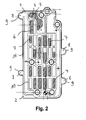
- Fig. 2 is a sketched view of the separator plate according to Fig. 1 with a metallic base plate 2, on which a filter material 3 is welded, which is covered by a second sealing material 4.
- the filter material 3 is shown only partially drawn in the region of the passages 7.
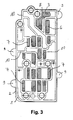
- Fig. 3 shows the rear view of the separator plate according to Fig. 2 , with a first sealing material 1.
- the first sealing material 1 comprises elastomer ribs 10, which form a channel system.
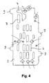
- Fig. 4 shows a metallic base plate 2, in which passages 7 are punched.
- the base plate 2 shows in all figures tongues 9, which protrude from the periphery of the base plate 2. On these tongues 9, the molten zones 8 of the filter material 3 are arranged, which produce the solid adhesion-free connection of the filter material 3 with the metallic base plate 2.
- a separator plate according to the Fig. 1 to 3 and Fig. 5 can be manufactured according to the following procedure:
- a metallic base plate 2 and the filter material 3 are manufactured and prepared independently of each other.
- the base plate 3 is provided with passages 7. This can be done by punching.
- the filter material 3 is adapted to the shape of the surface to be sealed. This can be done by cropping.
- the base plate 2 and the filter material 3 are stacked in a production tool.
- the production tool is provided with pins which press together the base plate 2 and the filter material 3 against displacement.
- the base plate 2 and the filter material 3 are thus fixed in exact relative position to each other.
- the production tool is closed by a top is brought into contact with a lower part.
- the base plate 2 and the filter material 3 are pressed against each other lying between the upper part and the lower part.
- the upper part and the lower part have a similar geometric shape as the filter material 3 and the base plate 2.
- the filter material 3 is kept flat when the upper part and the lower part are brought together.
- the production tool is provided with heating zones.
- the heating zones can generate high temperatures locally in a short time.
- induction heaters are used.
- the filter material 3 is flattened by the method described here in the molten zones 8.
- the filter material 3 is thinner in the molten zones 8 than in the non-molten areas.
- the molten zones 8 can also be inside or outside the fixed surface of the filter material 3.
- the molten zones 8 can also lie outside the surfaces to be sealed, which face the actuator half or the control half.
- the molten zones 8 may lie on tongues 9 of the base plate 2, which protrude from the periphery thereof.
- the sealing and filtering functions of the separator plate are not adversely affected by the molten zones 8 and their optional positioning, since they cause no increase in the thickness of the filter material 3 and the elastomer ribs 10 thus can not extend beyond regions.
- the resulting blank can be easily moved and processed. A displacement of the filter material 3 relative to the base plate 2 is not to be feared. Therefore, it is also possible to apply second sealing material 4 without any problems by screen printing, without the filter material 3 being displaced relative to the base plate 2.
- the method can be carried out particularly easily and quickly if a metallic material is selected for the base plate 2, which permits inductive heating of the base plate 2.
- the filter material 3 will be made of a material which forms a firm bond with the selected metal during the melting, for example synthetic polymers, in particular polyester. Surprisingly, polyesters solely by melting with some metals, a solid adhesive bond. An adhesive layer between the polyester and the metal is not necessary.
- a particularly advantageous effect of the method described above is the only local heating of the base plate 2 and the filter material 3 in the molten zones 8.
- the rest of the base plate 2 and the filter material 3 are subjected only to very low heat, which does not damage them.
- the process is therefore particularly gentle on materials.
Landscapes
- Engineering & Computer Science (AREA)
- General Engineering & Computer Science (AREA)
- Chemical & Material Sciences (AREA)
- Chemical Kinetics & Catalysis (AREA)
- Mechanical Engineering (AREA)
- Filtration Of Liquid (AREA)
- Filtering Materials (AREA)
- Processing And Handling Of Plastics And Other Materials For Molding In General (AREA)
- Cell Separators (AREA)
- Filtering Of Dispersed Particles In Gases (AREA)
- Centrifugal Separators (AREA)
Priority Applications (1)
| Application Number | Priority Date | Filing Date | Title |
|---|---|---|---|
| EP08016521A EP2039964B1 (fr) | 2007-09-19 | 2008-09-19 | Plaque de séparateur avec de matériau filtrant soudé au-dessus |
Applications Claiming Priority (2)
| Application Number | Priority Date | Filing Date | Title |
|---|---|---|---|
| EP07018358A EP2039963B1 (fr) | 2007-09-19 | 2007-09-19 | Plaque de séparateur |
| EP08016521A EP2039964B1 (fr) | 2007-09-19 | 2008-09-19 | Plaque de séparateur avec de matériau filtrant soudé au-dessus |
Publications (2)
| Publication Number | Publication Date |
|---|---|
| EP2039964A1 true EP2039964A1 (fr) | 2009-03-25 |
| EP2039964B1 EP2039964B1 (fr) | 2010-08-04 |
Family
ID=39013800
Family Applications (2)
| Application Number | Title | Priority Date | Filing Date |
|---|---|---|---|
| EP07018358A Not-in-force EP2039963B1 (fr) | 2007-09-19 | 2007-09-19 | Plaque de séparateur |
| EP08016521A Active EP2039964B1 (fr) | 2007-09-19 | 2008-09-19 | Plaque de séparateur avec de matériau filtrant soudé au-dessus |
Family Applications Before (1)
| Application Number | Title | Priority Date | Filing Date |
|---|---|---|---|
| EP07018358A Not-in-force EP2039963B1 (fr) | 2007-09-19 | 2007-09-19 | Plaque de séparateur |
Country Status (3)
| Country | Link |
|---|---|
| EP (2) | EP2039963B1 (fr) |
| AT (2) | ATE491105T1 (fr) |
| DE (2) | DE502007005904D1 (fr) |
Families Citing this family (1)
| Publication number | Priority date | Publication date | Assignee | Title |
|---|---|---|---|---|
| DE102010030072A1 (de) * | 2010-06-15 | 2011-12-15 | Federal-Mogul Sealing Systems Gmbh | Statistische Dichtung mit integriertem Sieb- oder Filterelement |
Citations (6)
| Publication number | Priority date | Publication date | Assignee | Title |
|---|---|---|---|---|
| WO1991011248A1 (fr) * | 1990-01-26 | 1991-08-08 | Gkss-Forschungszentrum Geesthacht Gmbh | Cadre d'etancheite pour empilement de membranes |
| JPH08229312A (ja) * | 1995-02-28 | 1996-09-10 | Tsuchiya Mfg Co Ltd | フィルタの製造方法 |
| EP0803654A2 (fr) * | 1996-04-24 | 1997-10-29 | Eaton Corporation | Valve multiple et filtre/joint d'étanchéité pour celui-ci |
| EP1121971A2 (fr) * | 2000-02-04 | 2001-08-08 | Kubota Corporation | Cartouche à membranes immergées et méthode de sa fabrication |
| US20030196750A1 (en) * | 2002-04-23 | 2003-10-23 | Aisan Kogyo Kabushiki Kaisha | Laser welding method |
| EP1862207A1 (fr) * | 2006-05-31 | 2007-12-05 | NV Bekaert SA | Eléments filtrants sous forme de disques et leurs procédés de fabrication |
Family Cites Families (8)
| Publication number | Priority date | Publication date | Assignee | Title |
|---|---|---|---|---|
| FR1590950A (fr) * | 1968-11-07 | 1970-04-20 | ||
| US3986915A (en) * | 1973-02-14 | 1976-10-19 | F. D. Farnam Co. | Unitized valve plate assembly method |
| DE3103464C2 (de) * | 1981-02-02 | 1984-10-11 | Gkss - Forschungszentrum Geesthacht Gmbh, 2054 Geesthacht | Dichtungsrahmen für Elektrodialyse-Membranstapel |
| DE3238732A1 (de) * | 1982-10-19 | 1984-04-19 | Siemens AG, 1000 Berlin und 8000 München | Gasblasenfaenger |
| DE3344187A1 (de) * | 1983-12-07 | 1985-07-04 | Seitz-Filter-Werke Theo & Geo Seitz GmbH und Co, 6550 Bad Kreuznach | Filtermembran mit abdichtung und verfahren zu ihrer herstellung |
| FR2577434B1 (fr) * | 1985-02-20 | 1987-07-03 | Cefilac | Procede de fabrication d'un support intercalaire de membranes semi-permeables |
| JP2714381B2 (ja) * | 1987-09-14 | 1998-02-16 | アイシン・エィ・ダブリュ株式会社 | セパレートプレート及びその製造方法 |
| JP2003049933A (ja) * | 2001-08-06 | 2003-02-21 | Denso Corp | 流体圧力制御装置 |
-
2007
- 2007-09-19 AT AT07018358T patent/ATE491105T1/de active
- 2007-09-19 EP EP07018358A patent/EP2039963B1/fr not_active Not-in-force
- 2007-09-19 DE DE502007005904T patent/DE502007005904D1/de active Active
-
2008
- 2008-09-19 AT AT08016521T patent/ATE476615T1/de active
- 2008-09-19 DE DE502008001066T patent/DE502008001066D1/de active Active
- 2008-09-19 EP EP08016521A patent/EP2039964B1/fr active Active
Patent Citations (6)
| Publication number | Priority date | Publication date | Assignee | Title |
|---|---|---|---|---|
| WO1991011248A1 (fr) * | 1990-01-26 | 1991-08-08 | Gkss-Forschungszentrum Geesthacht Gmbh | Cadre d'etancheite pour empilement de membranes |
| JPH08229312A (ja) * | 1995-02-28 | 1996-09-10 | Tsuchiya Mfg Co Ltd | フィルタの製造方法 |
| EP0803654A2 (fr) * | 1996-04-24 | 1997-10-29 | Eaton Corporation | Valve multiple et filtre/joint d'étanchéité pour celui-ci |
| EP1121971A2 (fr) * | 2000-02-04 | 2001-08-08 | Kubota Corporation | Cartouche à membranes immergées et méthode de sa fabrication |
| US20030196750A1 (en) * | 2002-04-23 | 2003-10-23 | Aisan Kogyo Kabushiki Kaisha | Laser welding method |
| EP1862207A1 (fr) * | 2006-05-31 | 2007-12-05 | NV Bekaert SA | Eléments filtrants sous forme de disques et leurs procédés de fabrication |
Also Published As
| Publication number | Publication date |
|---|---|
| ATE491105T1 (de) | 2010-12-15 |
| EP2039964B1 (fr) | 2010-08-04 |
| DE502007005904D1 (de) | 2011-01-20 |
| DE502008001066D1 (de) | 2010-09-16 |
| ATE476615T1 (de) | 2010-08-15 |
| EP2039963A1 (fr) | 2009-03-25 |
| EP2039963B1 (fr) | 2010-12-08 |
Similar Documents
| Publication | Publication Date | Title |
|---|---|---|
| DE102007058497B4 (de) | Mehrschichtige Leiterplatte und Verfahren zum Herstellen einer mehrschichtigen Leiterplatte | |
| DE69012019T2 (de) | Aussenschichtmaterial von einer gedruckten mehrschichtleiterplatte und verfahren zu deren herstellung. | |
| DE4419908C2 (de) | Verfahren zum Herstellen eines kaschierten Formteiles | |
| DE102009053666A1 (de) | Lötverfahren und Verbundbauteile, die mittels dieses Verfahrens verbunden sind | |
| CH707836B1 (de) | Verfahren zur Herstellung eines Gleitlagers. | |
| DE102010037336B4 (de) | Metallverbundkörper und Vorrichtung zum Herstellen des Metallverbundkörpers | |
| EP4081389A1 (fr) | Structure de couvercle et moule smc, et procédé de production d'une telle structure de couvercle | |
| DE112014006572T5 (de) | Systeme und verfahren zum verstärkten kleben | |
| DE102007023836A1 (de) | Hybrides Bauteil und Verfahren zu seiner Herstellung | |
| DE4118814C2 (de) | Verfahren zum Herstellen einer Mehrlagenplatte | |
| DE102014204113A1 (de) | Kunststoff-Kompositstruktur und Verfahren zu deren Herstellung | |
| EP2039964B1 (fr) | Plaque de séparateur avec de matériau filtrant soudé au-dessus | |
| AT4012U1 (de) | Vorrichtung und verfahren zur herstellung von fussbodenpaneelen | |
| WO2018197314A1 (fr) | Pièce moulée de soudure pour le soudage par diffusion, son procédé de fabrication et son procédé de montage | |
| DE102006049014B4 (de) | Verbundblech mit hohem Energieabsorptionsvermögen, Verfahren zu dessen Herstellung und Bauteil | |
| EP4403339A1 (fr) | Procédé de fabrication d'un composant hybride | |
| DE19859613C2 (de) | Presspaketaufbau und Verfahren zu dessen Herstellung | |
| EP1576864A1 (fr) | Plaque separatrice destinee a etre utilisee pour produire des composants de cartes de circuits imprimes | |
| EP1816387A1 (fr) | Composant plastique multicouche et procédé de montage de composants plastiques multicouches | |
| DE112022003978T5 (de) | Zusammengefügter Körper und Herstellungsverfahren für Metallbauteil, das für einen solchen zusammengefügten Körper verwendet wird | |
| DE69918086T2 (de) | Trennfolien aus stahllegierung und kupfer/stahl-verbundfolien zur anwendung in der herstellung von leiterplatten | |
| DE102005001367B4 (de) | Metallverstärkte Hybridstruktur | |
| DE1910026A1 (de) | Elektrische Flaechenheizeinrichtung und Verfahren zu deren Herstellung | |
| WO2017186930A1 (fr) | Plaque de distribution pour système hydraulique | |
| EP2451606B1 (fr) | Procédé pour la liaison étanche aux fluides de deux éléments de construction pour la fabrication d'une unité étanche aux fluides |
Legal Events
| Date | Code | Title | Description |
|---|---|---|---|
| PUAI | Public reference made under article 153(3) epc to a published international application that has entered the european phase |
Free format text: ORIGINAL CODE: 0009012 |
|
| AK | Designated contracting states |
Kind code of ref document: A1 Designated state(s): AT BE BG CH CY CZ DE DK EE ES FI FR GB GR HR HU IE IS IT LI LT LU LV MC MT NL NO PL PT RO SE SI SK TR |
|
| AX | Request for extension of the european patent |
Extension state: AL BA MK RS |
|
| 17P | Request for examination filed |
Effective date: 20090903 |
|
| AKX | Designation fees paid |
Designated state(s): AT BE BG CH CY CZ DE DK EE ES FI FR GB GR HR HU IE IS IT LI LT LU LV MC MT NL NO PL PT RO SE SI SK TR |
|
| GRAP | Despatch of communication of intention to grant a patent |
Free format text: ORIGINAL CODE: EPIDOSNIGR1 |
|
| GRAS | Grant fee paid |
Free format text: ORIGINAL CODE: EPIDOSNIGR3 |
|
| RIN1 | Information on inventor provided before grant (corrected) |
Inventor name: TEYTAUD, JEAN-LOUIS Inventor name: KOHN, JASON Inventor name: KOKOSZYNSKI, WOJCIECH Inventor name: TRABERT, JENS |
|
| GRAA | (expected) grant |
Free format text: ORIGINAL CODE: 0009210 |
|
| AK | Designated contracting states |
Kind code of ref document: B1 Designated state(s): AT BE BG CH CY CZ DE DK EE ES FI FR GB GR HR HU IE IS IT LI LT LU LV MC MT NL NO PL PT RO SE SI SK TR |
|
| REG | Reference to a national code |
Ref country code: GB Ref legal event code: FG4D Free format text: NOT ENGLISH |
|
| REG | Reference to a national code |
Ref country code: CH Ref legal event code: EP |
|
| REG | Reference to a national code |
Ref country code: IE Ref legal event code: FG4D Free format text: LANGUAGE OF EP DOCUMENT: GERMAN |
|
| REF | Corresponds to: |
Ref document number: 502008001066 Country of ref document: DE Date of ref document: 20100916 Kind code of ref document: P |
|
| REG | Reference to a national code |
Ref country code: NL Ref legal event code: VDEP Effective date: 20100804 |
|
| LTIE | Lt: invalidation of european patent or patent extension |
Effective date: 20100804 |
|
| PG25 | Lapsed in a contracting state [announced via postgrant information from national office to epo] |
Ref country code: FI Free format text: LAPSE BECAUSE OF FAILURE TO SUBMIT A TRANSLATION OF THE DESCRIPTION OR TO PAY THE FEE WITHIN THE PRESCRIBED TIME-LIMIT Effective date: 20100804 Ref country code: NO Free format text: LAPSE BECAUSE OF FAILURE TO SUBMIT A TRANSLATION OF THE DESCRIPTION OR TO PAY THE FEE WITHIN THE PRESCRIBED TIME-LIMIT Effective date: 20101104 Ref country code: NL Free format text: LAPSE BECAUSE OF FAILURE TO SUBMIT A TRANSLATION OF THE DESCRIPTION OR TO PAY THE FEE WITHIN THE PRESCRIBED TIME-LIMIT Effective date: 20100804 Ref country code: LT Free format text: LAPSE BECAUSE OF FAILURE TO SUBMIT A TRANSLATION OF THE DESCRIPTION OR TO PAY THE FEE WITHIN THE PRESCRIBED TIME-LIMIT Effective date: 20100804 |
|
| PG25 | Lapsed in a contracting state [announced via postgrant information from national office to epo] |
Ref country code: SI Free format text: LAPSE BECAUSE OF FAILURE TO SUBMIT A TRANSLATION OF THE DESCRIPTION OR TO PAY THE FEE WITHIN THE PRESCRIBED TIME-LIMIT Effective date: 20100804 Ref country code: IS Free format text: LAPSE BECAUSE OF FAILURE TO SUBMIT A TRANSLATION OF THE DESCRIPTION OR TO PAY THE FEE WITHIN THE PRESCRIBED TIME-LIMIT Effective date: 20101204 Ref country code: PL Free format text: LAPSE BECAUSE OF FAILURE TO SUBMIT A TRANSLATION OF THE DESCRIPTION OR TO PAY THE FEE WITHIN THE PRESCRIBED TIME-LIMIT Effective date: 20100804 Ref country code: BG Free format text: LAPSE BECAUSE OF FAILURE TO SUBMIT A TRANSLATION OF THE DESCRIPTION OR TO PAY THE FEE WITHIN THE PRESCRIBED TIME-LIMIT Effective date: 20101104 Ref country code: CY Free format text: LAPSE BECAUSE OF FAILURE TO SUBMIT A TRANSLATION OF THE DESCRIPTION OR TO PAY THE FEE WITHIN THE PRESCRIBED TIME-LIMIT Effective date: 20100804 Ref country code: HR Free format text: LAPSE BECAUSE OF FAILURE TO SUBMIT A TRANSLATION OF THE DESCRIPTION OR TO PAY THE FEE WITHIN THE PRESCRIBED TIME-LIMIT Effective date: 20100804 |
|
| REG | Reference to a national code |
Ref country code: IE Ref legal event code: FD4D |
|
| BERE | Be: lapsed |
Owner name: CARL FREUDENBERG K.G. Effective date: 20100930 |
|
| PG25 | Lapsed in a contracting state [announced via postgrant information from national office to epo] |
Ref country code: LV Free format text: LAPSE BECAUSE OF FAILURE TO SUBMIT A TRANSLATION OF THE DESCRIPTION OR TO PAY THE FEE WITHIN THE PRESCRIBED TIME-LIMIT Effective date: 20100804 Ref country code: GR Free format text: LAPSE BECAUSE OF FAILURE TO SUBMIT A TRANSLATION OF THE DESCRIPTION OR TO PAY THE FEE WITHIN THE PRESCRIBED TIME-LIMIT Effective date: 20101105 Ref country code: SE Free format text: LAPSE BECAUSE OF FAILURE TO SUBMIT A TRANSLATION OF THE DESCRIPTION OR TO PAY THE FEE WITHIN THE PRESCRIBED TIME-LIMIT Effective date: 20100804 |
|
| PG25 | Lapsed in a contracting state [announced via postgrant information from national office to epo] |
Ref country code: MC Free format text: LAPSE BECAUSE OF NON-PAYMENT OF DUE FEES Effective date: 20100930 Ref country code: IE Free format text: LAPSE BECAUSE OF FAILURE TO SUBMIT A TRANSLATION OF THE DESCRIPTION OR TO PAY THE FEE WITHIN THE PRESCRIBED TIME-LIMIT Effective date: 20100804 Ref country code: DK Free format text: LAPSE BECAUSE OF FAILURE TO SUBMIT A TRANSLATION OF THE DESCRIPTION OR TO PAY THE FEE WITHIN THE PRESCRIBED TIME-LIMIT Effective date: 20100804 |
|
| PG25 | Lapsed in a contracting state [announced via postgrant information from national office to epo] |
Ref country code: CZ Free format text: LAPSE BECAUSE OF FAILURE TO SUBMIT A TRANSLATION OF THE DESCRIPTION OR TO PAY THE FEE WITHIN THE PRESCRIBED TIME-LIMIT Effective date: 20100804 Ref country code: RO Free format text: LAPSE BECAUSE OF FAILURE TO SUBMIT A TRANSLATION OF THE DESCRIPTION OR TO PAY THE FEE WITHIN THE PRESCRIBED TIME-LIMIT Effective date: 20100804 Ref country code: EE Free format text: LAPSE BECAUSE OF FAILURE TO SUBMIT A TRANSLATION OF THE DESCRIPTION OR TO PAY THE FEE WITHIN THE PRESCRIBED TIME-LIMIT Effective date: 20100804 Ref country code: SK Free format text: LAPSE BECAUSE OF FAILURE TO SUBMIT A TRANSLATION OF THE DESCRIPTION OR TO PAY THE FEE WITHIN THE PRESCRIBED TIME-LIMIT Effective date: 20100804 |
|
| PLBE | No opposition filed within time limit |
Free format text: ORIGINAL CODE: 0009261 |
|
| STAA | Information on the status of an ep patent application or granted ep patent |
Free format text: STATUS: NO OPPOSITION FILED WITHIN TIME LIMIT |
|
| PG25 | Lapsed in a contracting state [announced via postgrant information from national office to epo] |
Ref country code: ES Free format text: LAPSE BECAUSE OF FAILURE TO SUBMIT A TRANSLATION OF THE DESCRIPTION OR TO PAY THE FEE WITHIN THE PRESCRIBED TIME-LIMIT Effective date: 20101115 |
|
| 26N | No opposition filed |
Effective date: 20110506 |
|
| PG25 | Lapsed in a contracting state [announced via postgrant information from national office to epo] |
Ref country code: BE Free format text: LAPSE BECAUSE OF NON-PAYMENT OF DUE FEES Effective date: 20100930 |
|
| REG | Reference to a national code |
Ref country code: DE Ref legal event code: R097 Ref document number: 502008001066 Country of ref document: DE Effective date: 20110506 |
|
| REG | Reference to a national code |
Ref country code: DE Ref legal event code: R081 Ref document number: 502008001066 Country of ref document: DE Owner name: ELRINGKLINGER AG, DE Free format text: FORMER OWNER: CARL FREUDENBERG KG, 69469 WEINHEIM, DE Effective date: 20111007 |
|
| PG25 | Lapsed in a contracting state [announced via postgrant information from national office to epo] |
Ref country code: MT Free format text: LAPSE BECAUSE OF FAILURE TO SUBMIT A TRANSLATION OF THE DESCRIPTION OR TO PAY THE FEE WITHIN THE PRESCRIBED TIME-LIMIT Effective date: 20100804 |
|
| PGFP | Annual fee paid to national office [announced via postgrant information from national office to epo] |
Ref country code: IT Payment date: 20110930 Year of fee payment: 4 |
|
| PG25 | Lapsed in a contracting state [announced via postgrant information from national office to epo] |
Ref country code: HU Free format text: LAPSE BECAUSE OF FAILURE TO SUBMIT A TRANSLATION OF THE DESCRIPTION OR TO PAY THE FEE WITHIN THE PRESCRIBED TIME-LIMIT Effective date: 20110205 Ref country code: LU Free format text: LAPSE BECAUSE OF NON-PAYMENT OF DUE FEES Effective date: 20100919 |
|
| PG25 | Lapsed in a contracting state [announced via postgrant information from national office to epo] |
Ref country code: TR Free format text: LAPSE BECAUSE OF FAILURE TO SUBMIT A TRANSLATION OF THE DESCRIPTION OR TO PAY THE FEE WITHIN THE PRESCRIBED TIME-LIMIT Effective date: 20100804 |
|
| REG | Reference to a national code |
Ref country code: CH Ref legal event code: PL |
|
| GBPC | Gb: european patent ceased through non-payment of renewal fee |
Effective date: 20120919 |
|
| PG25 | Lapsed in a contracting state [announced via postgrant information from national office to epo] |
Ref country code: PT Free format text: LAPSE BECAUSE OF NON-PAYMENT OF DUE FEES Effective date: 20100804 Ref country code: GB Free format text: LAPSE BECAUSE OF NON-PAYMENT OF DUE FEES Effective date: 20120919 Ref country code: CH Free format text: LAPSE BECAUSE OF NON-PAYMENT OF DUE FEES Effective date: 20120930 Ref country code: LI Free format text: LAPSE BECAUSE OF NON-PAYMENT OF DUE FEES Effective date: 20120930 |
|
| PG25 | Lapsed in a contracting state [announced via postgrant information from national office to epo] |
Ref country code: IT Free format text: LAPSE BECAUSE OF NON-PAYMENT OF DUE FEES Effective date: 20120919 |
|
| REG | Reference to a national code |
Ref country code: AT Ref legal event code: MM01 Ref document number: 476615 Country of ref document: AT Kind code of ref document: T Effective date: 20130919 |
|
| PG25 | Lapsed in a contracting state [announced via postgrant information from national office to epo] |
Ref country code: AT Free format text: LAPSE BECAUSE OF NON-PAYMENT OF DUE FEES Effective date: 20130919 |
|
| REG | Reference to a national code |
Ref country code: FR Ref legal event code: PLFP Year of fee payment: 8 |
|
| REG | Reference to a national code |
Ref country code: FR Ref legal event code: PLFP Year of fee payment: 9 |
|
| REG | Reference to a national code |
Ref country code: FR Ref legal event code: PLFP Year of fee payment: 10 |
|
| REG | Reference to a national code |
Ref country code: FR Ref legal event code: PLFP Year of fee payment: 11 |
|
| PGFP | Annual fee paid to national office [announced via postgrant information from national office to epo] |
Ref country code: DE Payment date: 20240919 Year of fee payment: 17 |
|
| PGFP | Annual fee paid to national office [announced via postgrant information from national office to epo] |
Ref country code: FR Payment date: 20240924 Year of fee payment: 17 |