EP2039968B1 - Steuervorrichtung mit perfektionierten Abdichtmitteln - Google Patents
Steuervorrichtung mit perfektionierten Abdichtmitteln Download PDFInfo
- Publication number
- EP2039968B1 EP2039968B1 EP08161575A EP08161575A EP2039968B1 EP 2039968 B1 EP2039968 B1 EP 2039968B1 EP 08161575 A EP08161575 A EP 08161575A EP 08161575 A EP08161575 A EP 08161575A EP 2039968 B1 EP2039968 B1 EP 2039968B1
- Authority
- EP
- European Patent Office
- Prior art keywords
- unit
- control device
- sealing
- translation
- driven unit
- Prior art date
- Legal status (The legal status is an assumption and is not a legal conclusion. Google has not performed a legal analysis and makes no representation as to the accuracy of the status listed.)
- Ceased
Links
- 238000007789 sealing Methods 0.000 title claims abstract description 51
- 230000000295 complement effect Effects 0.000 claims description 8
- 230000008878 coupling Effects 0.000 description 12
- 238000010168 coupling process Methods 0.000 description 12
- 238000005859 coupling reaction Methods 0.000 description 12
- 238000006073 displacement reaction Methods 0.000 description 5
- 230000000694 effects Effects 0.000 description 4
- 239000000428 dust Substances 0.000 description 2
- XLYOFNOQVPJJNP-UHFFFAOYSA-N water Substances O XLYOFNOQVPJJNP-UHFFFAOYSA-N 0.000 description 2
Images

Classifications
-
- F—MECHANICAL ENGINEERING; LIGHTING; HEATING; WEAPONS; BLASTING
- F16—ENGINEERING ELEMENTS AND UNITS; GENERAL MEASURES FOR PRODUCING AND MAINTAINING EFFECTIVE FUNCTIONING OF MACHINES OR INSTALLATIONS; THERMAL INSULATION IN GENERAL
- F16D—COUPLINGS FOR TRANSMITTING ROTATION; CLUTCHES; BRAKES
- F16D23/00—Details of mechanically-actuated clutches not specific for one distinct type
- F16D23/12—Mechanical clutch-actuating mechanisms arranged outside the clutch as such
-
- F—MECHANICAL ENGINEERING; LIGHTING; HEATING; WEAPONS; BLASTING
- F16—ENGINEERING ELEMENTS AND UNITS; GENERAL MEASURES FOR PRODUCING AND MAINTAINING EFFECTIVE FUNCTIONING OF MACHINES OR INSTALLATIONS; THERMAL INSULATION IN GENERAL
- F16D—COUPLINGS FOR TRANSMITTING ROTATION; CLUTCHES; BRAKES
- F16D28/00—Electrically-actuated clutches
-
- F—MECHANICAL ENGINEERING; LIGHTING; HEATING; WEAPONS; BLASTING
- F16—ENGINEERING ELEMENTS AND UNITS; GENERAL MEASURES FOR PRODUCING AND MAINTAINING EFFECTIVE FUNCTIONING OF MACHINES OR INSTALLATIONS; THERMAL INSULATION IN GENERAL
- F16J—PISTONS; CYLINDERS; SEALINGS
- F16J15/00—Sealings
- F16J15/50—Sealings between relatively-movable members, by means of a sealing without relatively-moving surfaces, e.g. fluid-tight sealings for transmitting motion through a wall
- F16J15/52—Sealings between relatively-movable members, by means of a sealing without relatively-moving surfaces, e.g. fluid-tight sealings for transmitting motion through a wall by means of sealing bellows or diaphragms
-
- F—MECHANICAL ENGINEERING; LIGHTING; HEATING; WEAPONS; BLASTING
- F16—ENGINEERING ELEMENTS AND UNITS; GENERAL MEASURES FOR PRODUCING AND MAINTAINING EFFECTIVE FUNCTIONING OF MACHINES OR INSTALLATIONS; THERMAL INSULATION IN GENERAL
- F16D—COUPLINGS FOR TRANSMITTING ROTATION; CLUTCHES; BRAKES
- F16D13/00—Friction clutches
- F16D13/58—Details
- F16D13/75—Features relating to adjustment, e.g. slack adjusters
- F16D13/752—Features relating to adjustment, e.g. slack adjusters the adjusting device being located in the actuating mechanism arranged outside the clutch
Definitions
- the present invention relates to a control device intended for example to be connected to a clutch of a motor vehicle.
- This control device comprises drive means of a driven member movable at least in translation between two retracted and protruding positions through an orifice formed in a fixed housing.
- the driven member is an elongate member movable longitudinally in translation and intended to be kinematically connected to a motor vehicle clutch.
- control device comprises sealing means between the housing and a portion of the driven member extending outside the housing, said part external.
- the sealing means comprise a bellows-shaped sealing member, surrounding the driven member, comprising a first end attached to the outer portion of the driven member and a second end attached to the housing.
- such a bellows is relatively bulky radially, because of the radial dimension of the folds of the bellows necessary for axial stretching of the bellows when the driven member moves between its protruding and retracted positions.
- this bellows is relatively bulky axially, due to the folds of the bellows which are bulky axially when the driven member is in the retracted position.
- the first sealing member having a second end sliding through the orifice, this sealing member is adapted to retract inside the housing when the driven member is in its retracted position.
- this sealing member is limited since it does not occupy space outside the housing in the retracted position.
- the first sealing member is slidable in the orifice without affecting the sealing of the device.
- the purpose of the invention is in particular to overcome sealing disadvantages by providing a control device of the aforementioned type.
- the subject of the invention is a control device of the aforementioned type in which the first sealing member comprises a rigid tubular element, forming the second end, connected to a sealed junction element forming the first end, this element junction being intended, if necessary, to deform radially and / or axially;
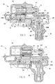
- control device 10 is intended to be connected to a motor vehicle clutch to control this clutch.
- the control device 10 comprises means 12 for driving in translation of a driven member 14 of elongate general shape in a so-called longitudinal direction.
- this driven member 14 is able to move at least in translation between a retracted position (represented on the figure 2 ) and a projecting position (shown on the figures 3 and 4 ), through an orifice 16 formed in a fixed casing 18 of the device 10.
- the driven member 14 is a translatable rod, intended to be kinematically connected to a motor vehicle clutch.
- the driven member 14 is intended to abut with a conventional control linkage member, preferably a motor vehicle clutch control fork.
- the driven member 14 could form a hydraulic control input member.
- the driven member would be a hydraulic cylinder piston rod, or a member integral with such a rod.
- the drive means 12 comprise an electric motor 20, fixed to the casing 18, the output shaft of which forms a driving member coupled to a driving pinion 22, directly or via gear means, for example gearing means. epicyclic reduction.
- the pinion 22 is intended to cooperate with a rack 24 kinematically connected to the driven member 14 by means which will be described in more detail later.
- the rack 24 is provided with a tooth surface defined by a flat tooth planar curve and a serration generating line, perpendicular to the plane of the tooth director, passing through this tooth guide.
- the control device 10 also comprises means 26 for assisting the driving of the driven member 14.
- These assistance means 26 comprise a cam 28 and elastic biasing means 30 of this cam.
- the cam 28 is provided with a cam surface defined by a planar camming curve and a cam generating line, perpendicular to the plane of the cam director, passing through this cam director.
- the resilient biasing means 30 comprise an elastic support member 32 having an axial effect, resiliently biased against the cam 28.
- the assistance member 32 comprises at least one thrust spring, for example two coaxial thrust springs. and housed one in the other.
- the elastic member 32 extends between a fixed seat 32F, whose position is independent of the elongation of the elastic member 32, and a movable seat 32M, whose position depends on the elongation of the elastic member 32 .
- the fixed seat 32F is secured to the housing 18 in which are housed the assistance means 26.
- the movable seat 32M carries a contact member 34 intended to cooperate with the cam 28.
- the contact member 34 comprises at least one roller intended to roll on the cam 28.
- the movable seat 32M carries a second roller 36, intended to cooperate with a flat wall 38 of the casing 18 to guide the movable seat 32M parallel to the axial effect of the assistance member 32.
- the drive means 12 and assistance 26 are coupled by means of a coupling member 40 kinematically connected to the driven member 14.
- the coupling member 40 carries the rack 24 and the cam 28.
- the coupling member 40 is formed by a single elongate piece, at the ends of which are respectively formed the rack 24 and the cam 28.
- the rack 24 and the cam 28 are arranged on the coupling member 40 so that the generatrix of teeth of the rack 24 is parallel to the generatrix of the cam 28.
- the device 10 comprises means 42 for guiding the coupling member 40 in translation.
- These guide means 42 comprise, for example, rollers 44A, 44B, respectively arranged at two ends of the coupling member 40, cooperating with each other. respectively with guide walls 46A, 46B provided on the housing 18.
- the control device 10 is initially considered in a position in which the clutch is for example in a disengaged configuration ( figure 2 ), the driven member 14 being in the retracted position.
- the roller 34 of the assistance means 26 cooperates with a first portion 28A of the surface of the cam 28.
- This surface portion 28A is preferably substantially perpendicular to the axis of the assistance member 32, or slightly inclined by relative to a plane perpendicular to this axis.
- the electric motor 20 is activated to drive the pinion 22 in a clutch direction.
- the relative position of the roller 34 relative to the cam 28 is modified so that this roller 34 cooperates with a second portion 28B of the surface of the cam, preferably more inclined than the first surface portion 28A.
- the coupling member 40 is biased elastically in the same direction as that imposed by the rotation of the pinion 22 in the clutch direction.
- the assistance means 26 thus assist the movement of the driven member 14 during the passage of a disengaged configuration to an engaged configuration of the clutch.
- clutch wear particularly frictional wear of the clutch, tends to increase the travel of the clutch fork 15 between its clutch and disengage control positions. .
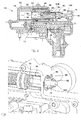
- control device 10 comprises wear-compensating means 48 intended to move the projecting end-of-travel position of the driven member, as can be seen on the figure 4 .
- the wear compensating means may be of a conventional type.
- the main elements of an exemplary embodiment of means 48 of wear catching without describing the details of their structure and operation known to those skilled in the art of wear-compensating devices will be described below.
- the wear-compensating means 48 comprise a telescopic member 50 for making up for wear.
- This telescopic member 50 comprises a first portion 52 kinematically connected to the drive means 12.
- this first portion 52 is fixed on the coupling member 40 by screws so that it is linked in translation with this member coupling 40.
- the control device 10 comprises rails 53 for guiding the telescopic member 50 in translation.
- the telescopic member 50 also comprises a second portion 54 intended to cooperate with the driven member 14 to drive it from its retracted position to its projecting position.
- the second portion 54 comprises a stop 56 capable of cooperating with the driven member 14 optionally slightly rotulante.
- the first 52 and second 54 parts are able to move in translation relative to each other, by cooperation of complementary threads carried by these first 52 and second parts 54.
- the first part 52 comprises a nut 58, free in rotation, provided with an internal thread cooperating with a complementary thread formed on the second part 54.
- the second part 54 moves in translation relative to the first part 52, thus displacing the projecting end position of the driven member 14.
- control device 10 comprises means 60 for sealing between the casing 18 and a portion 14E of the driven member extending outside. of the housing, said outer portion 14E. These sealing means 60 are visible in more detail on the figure 5 .
- the sealing means 60 comprise a first sealing member 62 surrounding the driven member 14.
- This first sealing member 62 comprises a rigid tubular element 64 connected to an element 66, generally of revolution shape, providing a sealed junction with the driven member 14.
- the joining element 66 forms a first end 62A of the first sealing member 62.
- This first end 62A is translationally connected to the outer portion 14E of the driven member 14 when the driven member 14 moves between its retracted positions and protruding.
- this junction element 66 is mounted sufficiently tightly around the driven member 14 so that the first sealing member 62 is driven in translation by the driven member 14 when the latter moves between its retracted and protruding positions. .
- this connecting element 66 is releasably connected in translation to the outer portion 14E of the driven member 14, to allow the displacement of the driven member 14 relative to the first sealing member 62 when the wear compensating means 48 displace the projecting end position of the driven member 14.
- the clamping of the connecting element 66 is calibrated to allow this displacement of the driven member 14 relative to the first member sealing 62.
- the connecting element 66 is sufficiently flexible to be able, if necessary, to deform radially and / or axially.
- this joining element 66 is radially sufficiently flexible so as not to exert a too great resistance force in the event of radial displacement of the driven member 14 (due to the rotulative cooperation of the member 14 with the telescopic member 50). Indeed, an excessive resistance force could damage this connecting element 66.
- the rigid tubular element 64 forms a second end 62B of the first sealing member 62, slidably mounted through the orifice 16 of the casing 18.
- the first sealing member 62 is therefore able to slide inside the casing 18 , which reduces its axial size outside the housing in the retracted position of the driven member 14.
- the rigid tubular element 64 also slides through a second annular sealing member 68 arranged between the contour of this orifice 16 and the second end 62B of the first sealing member 62.
- This second sealing member makes it possible to ensure sealing between the tubular element 64 and the casing 18.
- the tubular element 64 comprises a shoulder 70 forming a stop, intended to cooperate with a complementary stopper provided on the housing 18 when the driven member 14 is in the projecting position.
- This shoulder 70 also has grooves intended to cooperate with the guide rails 53 so as to guide the tubular element 64 in translation.
- the first sealing member 62 further comprises an abutment washer 71 arranged around the tubular element 64, intended to cooperate with a complementary stop abutment provided on the casing 18 when the driven member 14 is in the retracted position.
- the second portion 54 of the telescopic wear compensating member 50 is slidably dimensioned in the first sealing member 62, in particular in the rigid tubular element 64, when this second portion 54 is moves in translation relative to the first part 52.
- the second portion 54 and the rigid tubular element 64 do not interfere with each other during their respective displacements, and the second portion 54 does not risk damaging the first sealing member 62.
- the invention could be applied to a control device having no means of catching wear.
Landscapes
- Engineering & Computer Science (AREA)
- General Engineering & Computer Science (AREA)
- Mechanical Engineering (AREA)
- Physics & Mathematics (AREA)
- Electromagnetism (AREA)
- Mechanical Operated Clutches (AREA)
- Transmission Devices (AREA)
- Braking Arrangements (AREA)
- Paper (AREA)
- Auxiliary Devices For And Details Of Packaging Control (AREA)
- Electrical Discharge Machining, Electrochemical Machining, And Combined Machining (AREA)
- Diaphragms For Electromechanical Transducers (AREA)
- Heating, Cooling, Or Curing Plastics Or The Like In General (AREA)
- Sealing Devices (AREA)
Claims (10)
- Betätigungsvorrichtung (10), umfassend:- Mittel (12) zum Antrieb eines Abtriebsorgans (14), das zumindest translatorisch zwischen einer eingefahrenen und einer vorstehenden Position durch eine in ein festes Gehäuse (18) eingebrachte Öffnung (16) hindurch verschiebbar ist,- Abdichtungsmittel (60) zwischen dem Gehäuse (18) und einem als äußerer Teil (14E) bezeichneten Teil des Abtriebsorgans (14), der sich außerhalb des Gehäuses (18) erstreckt,wobei die Abdichtungsmittel (60) ein das Abtriebsorgan (14) umgebendes erstes Abdichtungsorgan (62) umfassen, welches umfasst:- ein erstes Endstück (62A), welches translatorisch an den äußeren Teil (14E) des Abtriebsorgans (14) gebunden ist, wenn dieses Abtriebsorgan (14) sich zwischen seiner eingefahrenen und vorstehenden Position verschiebt,- ein zweites Endstück (62B), welches verschiebbar durch die Öffnung (16) des Gehäuses (18) und ein zwischen der Kontur dieser Öffnung (16) und dem zweiten Endstück (62B) des ersten Abdichtungsorgans (62) angeordnetes zweites ringförmiges Abdichtungsorgan (68) montiert ist,dadurch gekennzeichnet, dass das erste Abdichtungsorgan (62) ein das zweite Endstück (62B) bildendes starres röhrenförmiges Element (64) umfasst, welches mit einem das erste Endstück (62A) bildenden dichten Anschlusselement (66) verbunden ist, wobei dieses Anschlusselement (66) dazu bestimmt ist, sich gegebenenfalls radial und/oder axial zu verformen.
- Betätigungsvorrichtung (10) nach Anspruch 1, wobei das erste Abdichtungsorgan (62) an seinem zweiten Endstück (62B) einen Vorsprung umfasst, der einen Anschlag bildet, welcher dazu bestimmt ist, mit einem an dem Gehäuse (18) vorgesehenen komplementären Endanschlag zusammenzuwirken, wenn das Abtriebsorgan (14) in der vorstehenden Position ist.
- Betätigungsvorrichtung (10) nach einem der vorherigen Ansprüche, wobei das erste Endstück (62A) des ersten Abdichtungsorgans (62) auf lösbare Art translatorisch an den äußeren Teil (14E) des Abtriebsorgans (14) gebunden ist.
- Betätigungsvorrichtung (10) nach einem der vorherigen Ansprüche, enthaltend Verschleißnachstellmittel (48), die dazu geeignet sind, die vorstehende Position des Abtriebsorgans (14) zu verschieben, umfassend ein teleskopisches Verschleißnachstellorgan (50), welches einen kinematisch mit den Antriebsmitteln (12) verbundenen ersten Teil (52) und einen zweiten Teil (54) umfasst, der dazu bestimmt ist, mit dem Abtriebsorgan (14) zusammen zuwirken, um es von seiner eingefahrenen Position zu seiner vorstehenden Position anzutreiben, wobei der erste Teil (52) und der zweite Teil (54) dazu geeignet sind, sich durch Zusammenwirken von komplementären Gewinden, welche von diesem ersten Teil (52) und zweiten Teil (54) getragen sind, relativ zueinander translatorisch zu verschieben.
- Betätigungsvorrichtung (10) nach Anspruch 4, wobei der zweite Teil (54) des teleskopischen Verschleißnachstellorgans (50) dazu ausgelegt ist, in dem ersten Abdichtungsorgan (62) gleiten zu können, wenn dieser zweite Teil (54) sich relativ zum ersten Teil (52) translatorisch verschiebt.
- Betätigungsvorrichtung (10) nach Anspruch 5, wobei der zweite Teil (54) des teleskopischen Verschleißnachstellorgans (50) dazu ausgelegt ist, in dem starren röhrenförmigen Element (64) gleiten zu können.
- Betätigungsvorrichtung (10) nach einem der vorherigen Ansprüche, wobei die Antriebsmittel (12) ein kinematisch mit der Welle eines Elektromotors (20) verbundenes Antriebsritzel (22) umfassen, welches mit einer Zahnstange (24) in Eingriff ist, die kinematisch mit dem Abtriebsorgan (14) verbunden ist.
- Betätigungsvorrichtung (10) nach einem der vorherigen Ansprüche, umfassend Mittel (26) zur Unterstützung des Antriebs des Abtrieborgans (14), die ein Unterstützungsorgan (32) aufweisen, welches elastisch gegen einen Nocken (28) beaufschlagt ist, beispielsweise ein Unterstützungsorgan (32) welches zumindest eine Druckfeder umfasst, die zwischen einem festen Sitz (32F) und einem beweglichen Sitz (32M) angeordnet ist, wobei der bewegliche Sitz (32M) ein Kontaktorgan (34) trägt, welches dazu bestimmt ist, mit dem Nocken (28) zusammenzuwirken.
- Betätigungsvorrichtung (10) nach einem der vorherigen Ansprüche, wobei das Abtriebsorgan (14) ein translatorisch verschiebbarer Stößel ist.
- Betätigungsvorrichtung (10) nach einem der vorherigen Ansprüche, wobei das Abtriebsorgan (14) dazu bestimmt ist, kinematisch mit einer Kupplung eines Kraftfahrzeugs verbunden zu werden.
Applications Claiming Priority (1)
| Application Number | Priority Date | Filing Date | Title |
|---|---|---|---|
| FR0757496A FR2920846B1 (fr) | 2007-09-11 | 2007-09-11 | Dispositif de commande a moyens d'etancheite perfectionnes |
Publications (2)
| Publication Number | Publication Date |
|---|---|
| EP2039968A1 EP2039968A1 (de) | 2009-03-25 |
| EP2039968B1 true EP2039968B1 (de) | 2010-12-22 |
Family
ID=39232838
Family Applications (1)
| Application Number | Title | Priority Date | Filing Date |
|---|---|---|---|
| EP08161575A Ceased EP2039968B1 (de) | 2007-09-11 | 2008-07-31 | Steuervorrichtung mit perfektionierten Abdichtmitteln |
Country Status (4)
| Country | Link |
|---|---|
| EP (1) | EP2039968B1 (de) |
| AT (1) | ATE492761T1 (de) |
| DE (1) | DE602008004035D1 (de) |
| FR (1) | FR2920846B1 (de) |
Cited By (1)
| Publication number | Priority date | Publication date | Assignee | Title |
|---|---|---|---|---|
| WO2018224749A1 (fr) | 2017-06-07 | 2018-12-13 | Psa Automobiles Sa | Commande pour vehicule automobile equipee d'un systeme d'etancheite comprenant une mise à l'air protegee |
Families Citing this family (2)
| Publication number | Priority date | Publication date | Assignee | Title |
|---|---|---|---|---|
| FR2976989B1 (fr) | 2011-06-23 | 2013-10-18 | Valeo Embrayages | Dispositif d'actionnement d'un embrayage, notamment pour vehicule automobile |
| KR101295114B1 (ko) * | 2012-06-28 | 2013-08-09 | 주식회사평화발레오 | 예압식 마모보상 클러치 액츄에이터 |
Family Cites Families (7)
| Publication number | Priority date | Publication date | Assignee | Title |
|---|---|---|---|---|
| FR651935A (fr) | 1927-05-04 | 1929-03-01 | Mica Fil S A | Procédé d'affaiblissement des champs marginaux de garnitures intérieures conductrices de condensateurs dans des isolateurs |
| GB881039A (en) * | 1958-11-26 | 1961-11-01 | Hydrosteer Ltd | Improvements in vehicular steering gear |
| US4617855A (en) * | 1984-08-15 | 1986-10-21 | Automotive Products Plc | Hydraulic slave cylinder switch |
| DE19700935A1 (de) * | 1996-01-31 | 1997-08-07 | Luk Getriebe Systeme Gmbh | Vorrichtung zur Betätigung eines Aggregates im Antriebsstrang eines Kraftfahrzeuges |
| DE19840368A1 (de) * | 1998-09-04 | 2000-03-09 | Mannesmann Sachs Ag | Stelleinrichtung mit einem Gehäuse |
| DE19943339A1 (de) * | 1999-09-10 | 2001-03-15 | Rohs Voigt Patentverwertungsge | Ausrückevorrichtung, insbesondere für eine Kupplung |
| DE10248829A1 (de) | 2002-10-19 | 2004-04-29 | Zf Friedrichshafen Ag | Schalteinrichtung |
-
2007
- 2007-09-11 FR FR0757496A patent/FR2920846B1/fr not_active Expired - Fee Related
-
2008
- 2008-07-31 AT AT08161575T patent/ATE492761T1/de not_active IP Right Cessation
- 2008-07-31 DE DE602008004035T patent/DE602008004035D1/de active Active
- 2008-07-31 EP EP08161575A patent/EP2039968B1/de not_active Ceased
Cited By (1)
| Publication number | Priority date | Publication date | Assignee | Title |
|---|---|---|---|---|
| WO2018224749A1 (fr) | 2017-06-07 | 2018-12-13 | Psa Automobiles Sa | Commande pour vehicule automobile equipee d'un systeme d'etancheite comprenant une mise à l'air protegee |
Also Published As
| Publication number | Publication date |
|---|---|
| EP2039968A1 (de) | 2009-03-25 |
| ATE492761T1 (de) | 2011-01-15 |
| DE602008004035D1 (de) | 2011-02-03 |
| FR2920846B1 (fr) | 2009-12-11 |
| FR2920846A1 (fr) | 2009-03-13 |
Similar Documents
| Publication | Publication Date | Title |
|---|---|---|
| FR2623580A1 (fr) | Dispositif de commande d'embrayage, notamment pour vehicules automobiles | |
| EP2604879B1 (de) | Vorrichtung zur selektiven Verbindung eines Getriebemotors mit einem Rad eines Luftfahrzeugs zum selektiven Antrieb dieses Rads durch den Getriebemotor | |
| EP2482632B1 (de) | Getriebe zwischen eine primäre angetriebene welle und eine ausgangswelle einer selbstfahrenden baumaschine | |
| EP2310245B1 (de) | Exzentrisches druckelement für die zahnstangenlenkung eines kraftfahrzeugs | |
| EP2350495B1 (de) | Aussermittige drückervorrichtung zum lenken eines kraftfahrzeugs | |
| EP2112402A1 (de) | Stellglied mit Haupt- und Nebenstange | |
| EP1996826B1 (de) | Losdrehsicherungsvorrichtung mit feder | |
| EP2039968A1 (de) | Steuervorrichtung mit perfektionierten Abdichtmitteln | |
| EP1329651B1 (de) | Bedienungsanordnung für ein automatisiertes Schaltgetriebe | |
| FR3069608B1 (fr) | Systeme de commande d’un verrou de parking pour bloquer une transmission d’un vehicule automobile | |
| EP2037143B1 (de) | Perfektionierte Steuervorrichtung | |
| EP3135971B1 (de) | Verbessertes system zum bremsen eines ventils | |
| WO2019025686A1 (fr) | Actionneur d'embrayage | |
| FR3059741A1 (fr) | "dispositif de couplage a crabot pour une boite de vitesses de vehicule automobile" | |
| WO2015044541A1 (fr) | Dispositif d'engagement de rapport pour transmission automatisee | |
| FR2738885A1 (fr) | Verin a pression fluide d'une chambre intermediaire coulissante | |
| FR3039860A1 (fr) | Dispositif de demarreur de moteur a combustion interne | |
| EP0169769B1 (de) | Betätigungseinrichtung mittels Bowdenzug insbesondere zum Schalten von Kraftfahrzeuggetrieben und Kraftfahrzeuggetrieben mit einer solchen Betätigungseinrichtung | |
| FR3012546A1 (fr) | Systeme d'entrainement en rotation d'une roue de vehicule automobile | |
| FR2731748A1 (fr) | Demarreur pour vehicule automobile muni de moyens perfectionnes de guidage du lanceur | |
| FR2886688A1 (fr) | Systeme de lancement d'un moteur thermique de vehicule automobile | |
| EP3350491B1 (de) | Vorrichtung zur umwandlung einer schwingbewegung eines zahnrads in eine übersetzungsbewegung eines schiebers und ventil mit solch einer vorrichtung | |
| FR2972410A1 (fr) | Dispositif d'essuie-glace a vis a billes et fourchette | |
| FR2903746A1 (fr) | Dispositif d'embrayage avec fonction tampon. | |
| WO2025186665A1 (fr) | Actionneur linéaire à indexation interne |
Legal Events
| Date | Code | Title | Description |
|---|---|---|---|
| PUAI | Public reference made under article 153(3) epc to a published international application that has entered the european phase |
Free format text: ORIGINAL CODE: 0009012 |
|
| 17P | Request for examination filed |
Effective date: 20080731 |
|
| AK | Designated contracting states |
Kind code of ref document: A1 Designated state(s): AT BE BG CH CY CZ DE DK EE ES FI FR GB GR HR HU IE IS IT LI LT LU LV MC MT NL NO PL PT RO SE SI SK TR |
|
| AX | Request for extension of the european patent |
Extension state: AL BA MK RS |
|
| 17Q | First examination report despatched |
Effective date: 20090615 |
|
| AKX | Designation fees paid |
Designated state(s): AT BE BG CH CY CZ DE DK EE ES FI FR GB GR HR HU IE IS IT LI LT LU LV MC MT NL NO PL PT RO SE SI SK TR |
|
| GRAP | Despatch of communication of intention to grant a patent |
Free format text: ORIGINAL CODE: EPIDOSNIGR1 |
|
| GRAS | Grant fee paid |
Free format text: ORIGINAL CODE: EPIDOSNIGR3 |
|
| GRAA | (expected) grant |
Free format text: ORIGINAL CODE: 0009210 |
|
| AK | Designated contracting states |
Kind code of ref document: B1 Designated state(s): AT BE BG CH CY CZ DE DK EE ES FI FR GB GR HR HU IE IS IT LI LT LU LV MC MT NL NO PL PT RO SE SI SK TR |
|
| REG | Reference to a national code |
Ref country code: GB Ref legal event code: FG4D Free format text: NOT ENGLISH |
|
| REG | Reference to a national code |
Ref country code: CH Ref legal event code: EP |
|
| REG | Reference to a national code |
Ref country code: IE Ref legal event code: FG4D |
|
| REF | Corresponds to: |
Ref document number: 602008004035 Country of ref document: DE Date of ref document: 20110203 Kind code of ref document: P |
|
| REG | Reference to a national code |
Ref country code: DE Ref legal event code: R096 Ref document number: 602008004035 Country of ref document: DE Effective date: 20110203 |
|
| REG | Reference to a national code |
Ref country code: NL Ref legal event code: VDEP Effective date: 20101222 |
|
| PG25 | Lapsed in a contracting state [announced via postgrant information from national office to epo] |
Ref country code: LT Free format text: LAPSE BECAUSE OF FAILURE TO SUBMIT A TRANSLATION OF THE DESCRIPTION OR TO PAY THE FEE WITHIN THE PRESCRIBED TIME-LIMIT Effective date: 20101222 |
|
| LTIE | Lt: invalidation of european patent or patent extension |
Effective date: 20101222 |
|
| PG25 | Lapsed in a contracting state [announced via postgrant information from national office to epo] |
Ref country code: SE Free format text: LAPSE BECAUSE OF FAILURE TO SUBMIT A TRANSLATION OF THE DESCRIPTION OR TO PAY THE FEE WITHIN THE PRESCRIBED TIME-LIMIT Effective date: 20101222 Ref country code: LV Free format text: LAPSE BECAUSE OF FAILURE TO SUBMIT A TRANSLATION OF THE DESCRIPTION OR TO PAY THE FEE WITHIN THE PRESCRIBED TIME-LIMIT Effective date: 20101222 Ref country code: SI Free format text: LAPSE BECAUSE OF FAILURE TO SUBMIT A TRANSLATION OF THE DESCRIPTION OR TO PAY THE FEE WITHIN THE PRESCRIBED TIME-LIMIT Effective date: 20101222 Ref country code: FI Free format text: LAPSE BECAUSE OF FAILURE TO SUBMIT A TRANSLATION OF THE DESCRIPTION OR TO PAY THE FEE WITHIN THE PRESCRIBED TIME-LIMIT Effective date: 20101222 Ref country code: HR Free format text: LAPSE BECAUSE OF FAILURE TO SUBMIT A TRANSLATION OF THE DESCRIPTION OR TO PAY THE FEE WITHIN THE PRESCRIBED TIME-LIMIT Effective date: 20101222 Ref country code: CY Free format text: LAPSE BECAUSE OF FAILURE TO SUBMIT A TRANSLATION OF THE DESCRIPTION OR TO PAY THE FEE WITHIN THE PRESCRIBED TIME-LIMIT Effective date: 20101222 Ref country code: BG Free format text: LAPSE BECAUSE OF FAILURE TO SUBMIT A TRANSLATION OF THE DESCRIPTION OR TO PAY THE FEE WITHIN THE PRESCRIBED TIME-LIMIT Effective date: 20110322 Ref country code: AT Free format text: LAPSE BECAUSE OF FAILURE TO SUBMIT A TRANSLATION OF THE DESCRIPTION OR TO PAY THE FEE WITHIN THE PRESCRIBED TIME-LIMIT Effective date: 20101222 |
|
| REG | Reference to a national code |
Ref country code: IE Ref legal event code: FD4D |
|
| PG25 | Lapsed in a contracting state [announced via postgrant information from national office to epo] |
Ref country code: NO Free format text: LAPSE BECAUSE OF FAILURE TO SUBMIT A TRANSLATION OF THE DESCRIPTION OR TO PAY THE FEE WITHIN THE PRESCRIBED TIME-LIMIT Effective date: 20110322 Ref country code: PT Free format text: LAPSE BECAUSE OF FAILURE TO SUBMIT A TRANSLATION OF THE DESCRIPTION OR TO PAY THE FEE WITHIN THE PRESCRIBED TIME-LIMIT Effective date: 20110422 Ref country code: IS Free format text: LAPSE BECAUSE OF FAILURE TO SUBMIT A TRANSLATION OF THE DESCRIPTION OR TO PAY THE FEE WITHIN THE PRESCRIBED TIME-LIMIT Effective date: 20110422 Ref country code: EE Free format text: LAPSE BECAUSE OF FAILURE TO SUBMIT A TRANSLATION OF THE DESCRIPTION OR TO PAY THE FEE WITHIN THE PRESCRIBED TIME-LIMIT Effective date: 20101222 Ref country code: CZ Free format text: LAPSE BECAUSE OF FAILURE TO SUBMIT A TRANSLATION OF THE DESCRIPTION OR TO PAY THE FEE WITHIN THE PRESCRIBED TIME-LIMIT Effective date: 20101222 Ref country code: ES Free format text: LAPSE BECAUSE OF FAILURE TO SUBMIT A TRANSLATION OF THE DESCRIPTION OR TO PAY THE FEE WITHIN THE PRESCRIBED TIME-LIMIT Effective date: 20110402 Ref country code: GR Free format text: LAPSE BECAUSE OF FAILURE TO SUBMIT A TRANSLATION OF THE DESCRIPTION OR TO PAY THE FEE WITHIN THE PRESCRIBED TIME-LIMIT Effective date: 20110323 |
|
| PG25 | Lapsed in a contracting state [announced via postgrant information from national office to epo] |
Ref country code: PL Free format text: LAPSE BECAUSE OF FAILURE TO SUBMIT A TRANSLATION OF THE DESCRIPTION OR TO PAY THE FEE WITHIN THE PRESCRIBED TIME-LIMIT Effective date: 20101222 Ref country code: RO Free format text: LAPSE BECAUSE OF FAILURE TO SUBMIT A TRANSLATION OF THE DESCRIPTION OR TO PAY THE FEE WITHIN THE PRESCRIBED TIME-LIMIT Effective date: 20101222 Ref country code: SK Free format text: LAPSE BECAUSE OF FAILURE TO SUBMIT A TRANSLATION OF THE DESCRIPTION OR TO PAY THE FEE WITHIN THE PRESCRIBED TIME-LIMIT Effective date: 20101222 Ref country code: NL Free format text: LAPSE BECAUSE OF FAILURE TO SUBMIT A TRANSLATION OF THE DESCRIPTION OR TO PAY THE FEE WITHIN THE PRESCRIBED TIME-LIMIT Effective date: 20101222 |
|
| PLBE | No opposition filed within time limit |
Free format text: ORIGINAL CODE: 0009261 |
|
| STAA | Information on the status of an ep patent application or granted ep patent |
Free format text: STATUS: NO OPPOSITION FILED WITHIN TIME LIMIT |
|
| PG25 | Lapsed in a contracting state [announced via postgrant information from national office to epo] |
Ref country code: IE Free format text: LAPSE BECAUSE OF FAILURE TO SUBMIT A TRANSLATION OF THE DESCRIPTION OR TO PAY THE FEE WITHIN THE PRESCRIBED TIME-LIMIT Effective date: 20101222 Ref country code: DK Free format text: LAPSE BECAUSE OF FAILURE TO SUBMIT A TRANSLATION OF THE DESCRIPTION OR TO PAY THE FEE WITHIN THE PRESCRIBED TIME-LIMIT Effective date: 20101222 |
|
| 26N | No opposition filed |
Effective date: 20110923 |
|
| PG25 | Lapsed in a contracting state [announced via postgrant information from national office to epo] |
Ref country code: MT Free format text: LAPSE BECAUSE OF FAILURE TO SUBMIT A TRANSLATION OF THE DESCRIPTION OR TO PAY THE FEE WITHIN THE PRESCRIBED TIME-LIMIT Effective date: 20101222 Ref country code: IT Free format text: LAPSE BECAUSE OF FAILURE TO SUBMIT A TRANSLATION OF THE DESCRIPTION OR TO PAY THE FEE WITHIN THE PRESCRIBED TIME-LIMIT Effective date: 20101222 |
|
| REG | Reference to a national code |
Ref country code: DE Ref legal event code: R097 Ref document number: 602008004035 Country of ref document: DE Effective date: 20110923 |
|
| BERE | Be: lapsed |
Owner name: VALEO EMBRAYAGES Effective date: 20110731 |
|
| PG25 | Lapsed in a contracting state [announced via postgrant information from national office to epo] |
Ref country code: MC Free format text: LAPSE BECAUSE OF NON-PAYMENT OF DUE FEES Effective date: 20110731 |
|
| PG25 | Lapsed in a contracting state [announced via postgrant information from national office to epo] |
Ref country code: BE Free format text: LAPSE BECAUSE OF NON-PAYMENT OF DUE FEES Effective date: 20110731 |
|
| REG | Reference to a national code |
Ref country code: CH Ref legal event code: PL |
|
| GBPC | Gb: european patent ceased through non-payment of renewal fee |
Effective date: 20120731 |
|
| PG25 | Lapsed in a contracting state [announced via postgrant information from national office to epo] |
Ref country code: LI Free format text: LAPSE BECAUSE OF NON-PAYMENT OF DUE FEES Effective date: 20120731 Ref country code: CH Free format text: LAPSE BECAUSE OF NON-PAYMENT OF DUE FEES Effective date: 20120731 Ref country code: GB Free format text: LAPSE BECAUSE OF NON-PAYMENT OF DUE FEES Effective date: 20120731 |
|
| PG25 | Lapsed in a contracting state [announced via postgrant information from national office to epo] |
Ref country code: LU Free format text: LAPSE BECAUSE OF NON-PAYMENT OF DUE FEES Effective date: 20110731 |
|
| PG25 | Lapsed in a contracting state [announced via postgrant information from national office to epo] |
Ref country code: TR Free format text: LAPSE BECAUSE OF FAILURE TO SUBMIT A TRANSLATION OF THE DESCRIPTION OR TO PAY THE FEE WITHIN THE PRESCRIBED TIME-LIMIT Effective date: 20101222 |
|
| PG25 | Lapsed in a contracting state [announced via postgrant information from national office to epo] |
Ref country code: HU Free format text: LAPSE BECAUSE OF FAILURE TO SUBMIT A TRANSLATION OF THE DESCRIPTION OR TO PAY THE FEE WITHIN THE PRESCRIBED TIME-LIMIT Effective date: 20101222 |
|
| REG | Reference to a national code |
Ref country code: FR Ref legal event code: PLFP Year of fee payment: 9 |
|
| REG | Reference to a national code |
Ref country code: FR Ref legal event code: PLFP Year of fee payment: 10 |
|
| REG | Reference to a national code |
Ref country code: FR Ref legal event code: PLFP Year of fee payment: 11 |
|
| PGFP | Annual fee paid to national office [announced via postgrant information from national office to epo] |
Ref country code: DE Payment date: 20190711 Year of fee payment: 12 Ref country code: FR Payment date: 20190731 Year of fee payment: 12 |
|
| REG | Reference to a national code |
Ref country code: DE Ref legal event code: R119 Ref document number: 602008004035 Country of ref document: DE |
|
| PG25 | Lapsed in a contracting state [announced via postgrant information from national office to epo] |
Ref country code: FR Free format text: LAPSE BECAUSE OF NON-PAYMENT OF DUE FEES Effective date: 20200731 |
|
| PG25 | Lapsed in a contracting state [announced via postgrant information from national office to epo] |
Ref country code: DE Free format text: LAPSE BECAUSE OF NON-PAYMENT OF DUE FEES Effective date: 20210202 |