EP2039969B1 - Soupape multivoie équipée de paires de joints de passage en forme d'éventail - Google Patents
Soupape multivoie équipée de paires de joints de passage en forme d'éventail Download PDFInfo
- Publication number
- EP2039969B1 EP2039969B1 EP07720463.4A EP07720463A EP2039969B1 EP 2039969 B1 EP2039969 B1 EP 2039969B1 EP 07720463 A EP07720463 A EP 07720463A EP 2039969 B1 EP2039969 B1 EP 2039969B1
- Authority
- EP
- European Patent Office
- Prior art keywords
- ring
- fan
- flow channel
- way valve
- sealing
- Prior art date
- Legal status (The legal status is an assumption and is not a legal conclusion. Google has not performed a legal analysis and makes no representation as to the accuracy of the status listed.)
- Active
Links
Images

Classifications
-
- F—MECHANICAL ENGINEERING; LIGHTING; HEATING; WEAPONS; BLASTING
- F16—ENGINEERING ELEMENTS AND UNITS; GENERAL MEASURES FOR PRODUCING AND MAINTAINING EFFECTIVE FUNCTIONING OF MACHINES OR INSTALLATIONS; THERMAL INSULATION IN GENERAL
- F16K—VALVES; TAPS; COCKS; ACTUATING-FLOATS; DEVICES FOR VENTING OR AERATING
- F16K11/00—Multiple-way valves, e.g. mixing valves; Pipe fittings incorporating such valves
- F16K11/02—Multiple-way valves, e.g. mixing valves; Pipe fittings incorporating such valves with all movable sealing faces moving as one unit
- F16K11/06—Multiple-way valves, e.g. mixing valves; Pipe fittings incorporating such valves with all movable sealing faces moving as one unit comprising only sliding valves, i.e. sliding closure elements
- F16K11/072—Multiple-way valves, e.g. mixing valves; Pipe fittings incorporating such valves with all movable sealing faces moving as one unit comprising only sliding valves, i.e. sliding closure elements with pivoted closure members
- F16K11/074—Multiple-way valves, e.g. mixing valves; Pipe fittings incorporating such valves with all movable sealing faces moving as one unit comprising only sliding valves, i.e. sliding closure elements with pivoted closure members with flat sealing faces
-
- E—FIXED CONSTRUCTIONS
- E21—EARTH OR ROCK DRILLING; MINING
- E21B—EARTH OR ROCK DRILLING; OBTAINING OIL, GAS, WATER, SOLUBLE OR MELTABLE MATERIALS OR A SLURRY OF MINERALS FROM WELLS
- E21B34/00—Valve arrangements for boreholes or wells
- E21B34/02—Valve arrangements for boreholes or wells in well heads
-
- Y—GENERAL TAGGING OF NEW TECHNOLOGICAL DEVELOPMENTS; GENERAL TAGGING OF CROSS-SECTIONAL TECHNOLOGIES SPANNING OVER SEVERAL SECTIONS OF THE IPC; TECHNICAL SUBJECTS COVERED BY FORMER USPC CROSS-REFERENCE ART COLLECTIONS [XRACs] AND DIGESTS
- Y10—TECHNICAL SUBJECTS COVERED BY FORMER USPC
- Y10T—TECHNICAL SUBJECTS COVERED BY FORMER US CLASSIFICATION
- Y10T137/00—Fluid handling
- Y10T137/8593—Systems
- Y10T137/86493—Multi-way valve unit
- Y10T137/86501—Sequential distributor or collector type
-
- Y—GENERAL TAGGING OF NEW TECHNOLOGICAL DEVELOPMENTS; GENERAL TAGGING OF CROSS-SECTIONAL TECHNOLOGIES SPANNING OVER SEVERAL SECTIONS OF THE IPC; TECHNICAL SUBJECTS COVERED BY FORMER USPC CROSS-REFERENCE ART COLLECTIONS [XRACs] AND DIGESTS
- Y10—TECHNICAL SUBJECTS COVERED BY FORMER USPC
- Y10T—TECHNICAL SUBJECTS COVERED BY FORMER US CLASSIFICATION
- Y10T137/00—Fluid handling
- Y10T137/8593—Systems
- Y10T137/86493—Multi-way valve unit
- Y10T137/86863—Rotary valve unit
Definitions
- the present invention relates to an oil-gas collection and transmission system for petroleum, chemistry industry and so on.
- a multi-way valve with fan-shaped flow channel sealing pair measures in turn the production of an individual well to obtain the dynamic production data of an oil well.
- the multi-way valve used in the oil industry mainly has two forms of the sealing pair, the plane sealing pair, for example, the Chinese Patent No. 200420006528.1 , and the cylindrical sealing pair.
- the valve seat sealing ring of a rotary multi-way valve with cylindrical sealing pair is made from flexible materials.
- the wear compensation is provided by an elastic component during the working process.
- the structure character of a rotary multi-way valve with the plane sealing pair is that: a plurality of round cross-section flow channel oil in lets being uniformly distributed along the circumference on a plane and the sealing pair of the valve seat sealing ring is made from hard alloy materials.
- a plurality of round cross-section flow channel oil inlets are in a larger size (such as 3" , 4" or 5") and under high-level pressure, however, it means that a plurality of round cross-section flow channel oil inlets should be uniformly distributed along the larger circumference on a plane. This results in a larger size, thicker wall and higher price of the valve body.
- the present invention is directed to keeping the advantages in the structure of a multi-way valve with the plane sealing pair while maintaining the size of the valve body to be substantially equivalent to that of the multi-way valve with the cylindrical sealing pair.
- the structure of multi-way valve with fan-shaped flow channel sealing pair is disclosed herein.
- the multi-way valve with fan-shaped flow channel sealing pair is characterized in that: a floating gating ring that is applied with contact specific pressure by an elastic component and an upper porous plane body form a gating plane sealing pair.
- a plurality of fan-shaped flow channel oil inlet holes are annularly and uniformly distributed on the mating surface of the upper porous plane body.
- the inner part of the middle rotary spool is used as a public flow-guide passage.
- the floating gating ring is configured such that it changes gradually from the upper fan-shaped flow channel to the lower round-shaped flow channel.
- the inner public flow-guide metering passage of the middle rotary spool is in communication with a certain fan-shaped flow channel oil inlet hole located in the mating surface of the upper porous plane body when the middle rotary spool is rotated by electrical power or manual power to a certain angle.
- the floating gating ring is pre-exerted by an elastic force to make the sealing face self-sealed under a contact specific pressure.
- the present invention has a compact structure.
- the flow channels are formed by casting. The sands carried in the fluid cannot enter into the sealing face easily when the fluid flows down from the top to the bottom. The precise processing can be executed in the planar mechanism easily, thereby enabling a lower machining cost, reliable sealing and a longer working life.
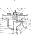
- the multi-way valve with fan-shaped flow channel sealing pair comprises a metering outlet welding flange, a lower O-ring seal, a sliding support ring, a valve body, a middle rotary spool, a valve body O-ring seal, a sealing gasket, fluid inlet welding flanges, connecting bolt and nuts, an upper porous plane body, a connecting electric actuator intermediate flange, an internal hexagon adjusting fixing plate, an adjusting nut, a conical roller bearing, a shaft head O-ring seal, a porthole plug, a floating gating ring, a floating gating ring O-ring seal, an auxiliary sealing ring, an auxiliary sealing support ring, a bellow or dish-shaped spring, a seating ring socket head adjusting nut, a collection and transmission outlet welding flange etc.
- the inner public flow-guide metering passage of the rotary spool is in communication with a certain oil inlet hole located in the mating surface of the upper porous plane body when the rotary spool is rotated by electrical power or manual power to a certain angle.
- the present invention has the following advantages : the floating gating ring that is applied with contact specific pressure by an elastic component and an upper porous plane body form a gating plane sealing pair, and a plurality of fan-shaped flow channel oil inlet holes are annularly and uniformly distributed on the mating surface of the upper porous plane body.
- the arrangement of this fan-shaped flow channel cross-section is more compact compared with the condition for arranging the round flow channel cross-section oil inlet holes in a circle.
- the diameter of the valve body is reduced by 15-40% and it is equivalent to the size of the cylindrical structure.
- the present invention is directed to keeping the advantages in the structure of a multi-way valve with the plane sealing pair while maintaining the size of the valve body be substantially equivalent to that of the multi-way valve with the cylindrical sealing pair.
- the floating gating ring is pre-exerted by an elastic force to make the sealing face self-sealed under a contact specific pressure.
- the plug can be opened and the seating ring socket head adjusting nut can be adjusted by a special tool. Therefore, the floating gating ring is applied a force by an elastic component.
- the fan-shaped flow channels are formed by precision casting.
- the floating gating ring is configured by precision casting such that it changes gradually from the upper fan-shaped flow channel to the lower round-shaped flow channel. The whole structure is formed so that the sands carried in the fluid can not enter into the sealing face easily when the fluid flows down from the top to the bottom.
- the planer sealing using the rotary sealing pair is more reliable with long service life at lower manufacture costs.
- a preferred embodiment of a multi-way valve with fan-shaped flow channel sealing pair having twelve way in an individual well with inlet diameter DN 100mm, metering outlet diameter DN 100mm and a collection and transmission outlet diameter DN200mm is described.
- the valve body 4 is a cast.
- the dimension of the metering outlet welding flange 1 is the same as that of twelve individual well fluid inlet flanges 8 of DN100mm, and the diameter of a collection and transmission outlet welding flange 23 is 200 mm.
- the metering outlet welding flange 1 and the collection and transmission outlet welding flange 23 are both butt welded onto the valve body 4.
- the upper porous plane body 10 is formed by precision cast.
- Twelve fluid inlet flow channels of an individual well with DN100mm are configured such that they change gradually from horizontal round sections to fan-shaped flow channels in the vertical section when turning into 90°direction .
- the area of fan-shaped sections is equal to that of the round horizontal sections.
- the mating surface of the upper porous plane body is processed by chromate treatment or is spraying welded with hard alloy, and followed by precisely planar grinding.
- the middle rotary spool 5 and a floating gating ring 17 are machined by casting.
- the floating gating ring 17 is configured such that it changes gradually from the upper fan-shaped flow channel to the lower round-shaped flow channel.
- the mating surface of the upper fan-shaped flow channel sealing pair of the floating gating ring 17 is spraying welded by hard alloy, and followed by precisely planar grinding.
- the floating gating ring 17 is welded with a positioning pin which is embedded into the middle rotary spool 5 to make the floating gating ring 17 rotate along with the middle rotary spool 5 all the time and to maintain the sealing aperture of the fan-shaped flow channel of the floating gating ring 17 in alignment with the mating seal aperture of one of twelve fan-shaped flow channels of the upper porous plane body 10.
- the assembly process is as follows.
- the sliding support ring 3 with the lower O-ring seal 2 is first put into the mating seat of the valve body 4, and then the middle rotary spool 5 assembly is placed into the valve body 4.
- the seating ring socket head adjusting nut 22 is screwed into the bottom of the valve seat of the middle rotary spool 5.
- a bellow or dish-shaped spring 21, an auxiliary sealing support ring 20, an auxiliary sealing ring 19, a floating gating ring O-ring seal 18, the floating gating ring 17 are put in turn.
- the upper porous plane body 10 is connected to the valve body 4 by connecting bolt and nuts 9.
- a conical roller bearing 14 is placed and a adjusting nut 13 is screwed.
- An internal hexagon adjusting fixing plate 12 is put on the top of the adjusting nut 13. Stop screws are tightened, and a connecting electric actuator intermediate flange 11 is connected.
- the contact seal specific pressure of the floating gating ring 17 is realized by the following steps: a special adjusting tool is put into the plug opening of the upper porous plane body 10 to adjust the seating ring socket head adjusting nut 22 so that the bellow or dish-shaped spring 21 is deformed under pressure. Then an elastic force is transmitted to the floating gating ring 17 by the auxiliary sealing ring 19 and the auxiliary sealing support ring 20 so that contact seal specific pressure is obtained by the floating gating ring 17.
- the working process of the present invention is as follows.
- the floating gating ring 17 is in alignment with a certain fan-shaped flow channel oil inlet hole located in the mating surface of the upper porous plane body 10 when the middle rotary spool 5 is rotated by electrical power or manual power to a certain angle, so that the inner public flow-guide metering passage of the middle rotary spool 5 is in communication with a certain fan-shaped flow channel oil inlet hole located in the mating surface of the upper porous plane body 10 and the rotary gating for measurement can be realized.
- the fluid from remaining fan-shaped flow channel fluid inlet holes of the upper porous plane body 10 is converged and enters into a collection and transmission passage through the collection and transmission outlet welding flange 23 mounted to the bottom side of valve body 4.
Landscapes
- Engineering & Computer Science (AREA)
- General Engineering & Computer Science (AREA)
- Mining & Mineral Resources (AREA)
- Geology (AREA)
- Life Sciences & Earth Sciences (AREA)
- Fluid Mechanics (AREA)
- Environmental & Geological Engineering (AREA)
- Physics & Mathematics (AREA)
- Mechanical Engineering (AREA)
- General Life Sciences & Earth Sciences (AREA)
- Geochemistry & Mineralogy (AREA)
- Sliding Valves (AREA)
- Lift Valve (AREA)
- Taps Or Cocks (AREA)
- Float Valves (AREA)
Claims (5)
- Soupape multivoie avec une paire de joints de canal de circulation en forme d'éventail comprenant une bride soudée de sortie de mesure (1), un joint torique inférieur (2), un anneau de support coulissant (3), un corps de soupape (4), une bobine rotative centrale (5), un joint torique de corps de soupape (6), un joint d'étanchéité (7), des brides soudées d'arrivée de fluide (7), des boulons et écrous de raccordement (9), un corps plan poreux supérieur (10), une bride intermédiaire d'actionneur électrique de connexion (11), une plaque de fixation d'ajustement d'hexagone interne (12), un écrou d'ajustement (13), un palier conique à rouleaux (14), un joint torique de tête d'arbre (15), un bouchon de hublot (16), un anneau de déclenchement flottant (17), un joint torique d'anneau de déclenchement flottant (18), une bague d'étanchéité auxiliaire (19), un anneau de support de joint auxiliaire (20), un composant élastique en forme de soufflet ou de ressort en forme de disque (21), un écrou d'ajustement de bague de siège à douille (22), une bride soudée de sortie de collecte et de transmission (23),
où l'anneau de déclenchement flottant (17), sur lequel le composé élastique exerce une pression de contact spécifique, et le corps plan poreux supérieur (10) forment une paire de joints de déclenchement plans ;
une pluralité d'orifices d'arrivée de pétrole de canal de circulation en forme d'éventail sont distribués en anneau et de manière uniforme sur la surface correspondante du corps plan poreux supérieur (10) ;
la partie intérieure de la bobine rotative centrale (5) est utilisée comme passage de guidage de circulation public ; et
l'anneau de déclenchement flottant (17) est configuré de telle manière qu'il passe progressivement d'une section de canal de circulation en forme d'éventail supérieure à une section de canal de circulation circulaire inférieure. - Soupape multivoie selon la revendication 1, caractérisée en ce que : des canaux de circulation d'arrivée de fluide de puits individuels du corps plan poreux supérieur (10) sont configurés de telle manière qu'ils tournent de 90° en passant progressivement de sections circulaires horizontales à des sections verticales en forme d'éventail, où la surface des sections en forme d'éventail est égale à celle des sections horizontales circulaires.
- Soupape multivoie selon la revendication 1, caractérisée en ce que: l'anneau de déclenchement flottant (17) est raccordé à une goupille de positionnement intégrée à la bobine rotative centrale (5) pour constamment faire tourner l'anneau de déclenchement flottant (17) le long de la bobine rotative centrale (5) et pour maintenir l'alignement de l'ouverture de joint du canal de circulation en forme d'éventail de l'anneau de déclenchement flottant (17) avec l'ouverture de joint correspondante de l'un des canaux de circulation en forme d'éventail du corps plan poreux supérieur (10).
- Procédé d'assemblage de la soupape multivoie avec une paire de joints de canal de circulation en forme d'éventail selon l'une quelconque des revendications 1 à 3, caractérisé en ce qu'elle comprend les étapes suivantes :placer d'abord l'anneau de support coulissant (3) avec le joint torique inférieur (2) dans un siège d'accouplement du corps de soupape (4),puis placer l'ensemble de bobine rotative centrale (5) dans le corps de soupape (4),visser l'écrou d'ajustement de bague de siège à douille (22) dans le bas d'un siège de soupape de la bobine rotative centrale (5),puis, placer l'un après l'autre le soufflet ou le ressort en forme de disque (21), l'anneau de support de joint auxiliaire (20), la bague d'étanchéité auxiliaire (19), le joint torique d'anneau de déclenchement flottant (18) et l'anneau de déclenchement flottant (17),puis, connecter le corps plan poreux supérieur (10) au corps de soupape (4) au moyen des boulons et écrous de raccordement (9),placer le palier à roulement conique (14) et visser l'écrou d'ajustement (13),régler une quantité appropriée de jeu de mouvement supérieur, inférieur et radial en tournant l'écrou d'ajustement (13) depuis l'extérieur de la soupape multivoie de manière à le déplacer vers le bas de telle sorte que la force exercée sur le palier à roulement conique (14) est transmise à la bobine rotative centrale (5),puis placer la plaque de fixation d'ajustement d'hexagone interne (12) sur l'écrou d'ajustement (13) et fixer la plaque de fixation d'ajustement d'hexagone interne (12),serrer les vis supérieures, etconnecter la bride intermédiaire d'actionneur électrique de connexion (11).
- Procédé pour ajuster la pression spécifique de joint de contact de l'anneau de déclenchement flottant (17) dans la soupape multivoie selon l'une quelconque des revendications 1 à 3, caractérisé en ce que après que le bouchon de hublot (16) est ouvert et l'écrou d'ajustement de bague de siège à douille (22) est ajusté au moyen d'un outil d'ajustement spécial, la force est appliquée à l'anneau de déclenchement flottant (17) par le composant élastique.
Applications Claiming Priority (2)
| Application Number | Priority Date | Filing Date | Title |
|---|---|---|---|
| CNU2006201670764U CN201034178Y (zh) | 2006-12-11 | 2006-12-11 | 扇形流道密封副多通阀 |
| PCT/CN2007/000888 WO2008071044A1 (fr) | 2006-12-11 | 2007-03-19 | Soupape multivoie équipée de paires de joints de passage en forme d'éventail |
Publications (3)
| Publication Number | Publication Date |
|---|---|
| EP2039969A1 EP2039969A1 (fr) | 2009-03-25 |
| EP2039969A4 EP2039969A4 (fr) | 2015-05-13 |
| EP2039969B1 true EP2039969B1 (fr) | 2017-12-27 |
Family
ID=39195069
Family Applications (1)
| Application Number | Title | Priority Date | Filing Date |
|---|---|---|---|
| EP07720463.4A Active EP2039969B1 (fr) | 2006-12-11 | 2007-03-19 | Soupape multivoie équipée de paires de joints de passage en forme d'éventail |
Country Status (6)
| Country | Link |
|---|---|
| US (1) | US8100143B2 (fr) |
| EP (1) | EP2039969B1 (fr) |
| CN (1) | CN201034178Y (fr) |
| CA (1) | CA2644122C (fr) |
| EA (1) | EA014703B1 (fr) |
| WO (1) | WO2008071044A1 (fr) |
Families Citing this family (26)
| Publication number | Priority date | Publication date | Assignee | Title |
|---|---|---|---|---|
| US10180212B2 (en) | 2009-03-30 | 2019-01-15 | Westport Power Inc. | Method and system for controlling fluid flow from a storage tank through a supply line to an end user |
| RU2463439C1 (ru) * | 2011-04-26 | 2012-10-10 | Общество с ограниченной ответственностью Финансово-промышленная компания "Космос-Нефть-Газ" | Обратный клапан |
| RU2463437C1 (ru) * | 2011-04-26 | 2012-10-10 | Общество с ограниченной ответственностью Финансово-промышленная компания "Космос-Нефть-Газ" | Обратный клапан |
| RU2463438C1 (ru) * | 2011-04-26 | 2012-10-10 | Общество с ограниченной ответственностью Финансово-промышленная компания "Космос-Нефть-Газ" | Способ обогрева запорного органа обратного клапана |
| US8256538B1 (en) | 2011-11-10 | 2012-09-04 | John Mayn Deslierres | Containment system for oil field riser pipes |
| CN103939641A (zh) * | 2013-01-21 | 2014-07-23 | 克拉玛依市金牛信泰石油设备有限公司 | 多路阀 |
| CN104033150A (zh) * | 2013-03-08 | 2014-09-10 | 克拉玛依市金牛信泰石油设备有限公司 | 高温原油自动取样系统 |
| CN104047568B (zh) * | 2013-03-13 | 2017-04-12 | 中国石油天然气股份有限公司 | 一种可调式圆盘油嘴阀及采油气出口产量的控制方法 |
| CN104047569B (zh) * | 2013-03-13 | 2017-05-10 | 中国石油天然气股份有限公司 | 一种多功能旋调式油嘴阀装置及使用方法 |
| BR112016003526B1 (pt) | 2013-08-27 | 2022-03-03 | A.R.I. Flow Control Accessories Ltd | Válvula de descarga de líquido |
| CN103939051A (zh) * | 2014-04-25 | 2014-07-23 | 北京迪威尔石油天然气技术开发有限公司 | 一种多通阀及该多通阀的加工方法 |
| CN105202225B (zh) | 2014-06-10 | 2017-12-22 | 克拉玛依市金牛信泰石油设备有限公司 | 阀座环及具有该阀座环的多路阀 |
| RU2569387C1 (ru) * | 2014-07-25 | 2015-11-27 | Роман Валентинович Маслов | Обратный клапан и способ обогрева его запорного органа |
| US9790765B2 (en) * | 2014-10-06 | 2017-10-17 | Ge Oil & Gas Pressure Control Lp | Non-parallel multi-bore sealing device |
| EP3045790A1 (fr) * | 2015-01-15 | 2016-07-20 | MANN+HUMMEL GmbH | Dispositif de contrôle de fluides |
| CN105987200B (zh) | 2015-02-04 | 2019-08-06 | 芜湖金牛信泰石油设备有限公司 | 多路阀 |
| CN104613037B (zh) | 2015-02-04 | 2016-03-16 | 芜湖金牛信泰石油设备有限公司 | 多路阀及其多路阀撬 |
| CN105065721A (zh) * | 2015-08-05 | 2015-11-18 | 北京双良石油技术有限公司 | 一种计量分配器 |
| RU2606471C1 (ru) * | 2015-10-08 | 2017-01-10 | Общество с ограниченной ответственностью "Электро" | Клапан обратный устьевой быстросъемный |
| CN107606196A (zh) * | 2017-10-18 | 2018-01-19 | 兰州高压阀门有限公司 | 一种超耐磨零泄漏罐底阀门 |
| CN110566151B (zh) * | 2019-09-03 | 2024-05-03 | 辽宁省有色地质一〇一队有限责任公司 | 孔口钻杆浮动密封装置 |
| CN111609166B (zh) * | 2020-06-23 | 2024-12-20 | 福建开立通科技有限公司 | 一种全自紧密封圆台阀及其加工装配方法 |
| CN113565966A (zh) * | 2021-06-08 | 2021-10-29 | 江苏嘉胜石油科技有限公司 | 一种高强度油气回收阀 |
| CN113289382B (zh) * | 2021-07-28 | 2021-10-08 | 山东鹤鹏技术有限公司 | 基于多台伺服马达同时运转的石油化工用流体分配装置 |
| CN113769533B (zh) * | 2021-10-27 | 2025-07-11 | 烟台华伊绿能科技有限公司 | 一种可控负压挥发性有机物旋流冷却组件 |
| CN114001175B (zh) * | 2021-10-28 | 2022-11-25 | 浙江银轮机械股份有限公司 | 一种多通阀 |
Family Cites Families (14)
| Publication number | Priority date | Publication date | Assignee | Title |
|---|---|---|---|---|
| US2835273A (en) * | 1953-09-08 | 1958-05-20 | Frank A Mcdonald | Manifold valve with selective by-pass rotor |
| US2996083A (en) * | 1958-07-10 | 1961-08-15 | Huska Paul | Continuous flow rotary selector valve |
| NL241945A (fr) | 1958-08-04 | |||
| US3433265A (en) * | 1967-02-27 | 1969-03-18 | Komline Sanderson Eng Corp | Balanced rotary valve |
| US4989641A (en) * | 1989-10-11 | 1991-02-05 | Santa Fe Energy Co. | Rotary selector valve |
| US5927330A (en) | 1996-02-06 | 1999-07-27 | Oil States Industries | Modular, high-volume, rotary selector valve |
| CN2279484Y (zh) | 1996-08-24 | 1998-04-22 | 张广义 | 多通分配阀 |
| US5727596A (en) * | 1997-02-25 | 1998-03-17 | Fmc Corporation | Changeover valve |
| JP2886850B1 (ja) | 1998-04-02 | 1999-04-26 | 富士インジェクタ株式会社 | 冷暖房装置における冷媒ガスの流路切換装置 |
| CN2572159Y (zh) | 2002-08-13 | 2003-09-10 | 北京迪威尔石油天然气技术开发有限公司 | 计量集输多通阀 |
| CN2709740Y (zh) | 2004-02-27 | 2005-07-13 | 克拉玛依金牛信泰工业控制有限公司 | 计量集输选通装置 |
| US7343932B2 (en) * | 2004-04-27 | 2008-03-18 | Cameron International Corporation | Multiple line administration |
| US7343933B2 (en) * | 2004-04-27 | 2008-03-18 | Cameron International Corporation | Multi-port flow selector manifold valve and manifold system |
| CN2736615Y (zh) | 2004-07-19 | 2005-10-26 | 克拉玛依市金牛信泰工业控制有限公司 | 集成关断阀一体的计量集输选通装置 |
-
2006
- 2006-12-11 CN CNU2006201670764U patent/CN201034178Y/zh not_active Expired - Lifetime
-
2007
- 2007-03-19 EA EA200900379A patent/EA014703B1/ru unknown
- 2007-03-19 CA CA 2644122 patent/CA2644122C/fr active Active
- 2007-03-19 WO PCT/CN2007/000888 patent/WO2008071044A1/fr not_active Ceased
- 2007-03-19 US US12/311,014 patent/US8100143B2/en active Active
- 2007-03-19 EP EP07720463.4A patent/EP2039969B1/fr active Active
Non-Patent Citations (1)
| Title |
|---|
| None * |
Also Published As
| Publication number | Publication date |
|---|---|
| EP2039969A4 (fr) | 2015-05-13 |
| US8100143B2 (en) | 2012-01-24 |
| CA2644122A1 (fr) | 2008-06-19 |
| EA200900379A1 (ru) | 2010-02-26 |
| WO2008071044A1 (fr) | 2008-06-19 |
| CA2644122C (fr) | 2012-05-22 |
| US20090320947A1 (en) | 2009-12-31 |
| EP2039969A1 (fr) | 2009-03-25 |
| CN201034178Y (zh) | 2008-03-12 |
| EA014703B1 (ru) | 2011-02-28 |
Similar Documents
| Publication | Publication Date | Title |
|---|---|---|
| CA2644122C (fr) | Soupape multivoie equipee de paires de joints de passage en forme d'eventail | |
| US9534696B2 (en) | Ball valve | |
| RU2510475C1 (ru) | Запорный клапан с невыдвижным шпинделем | |
| AU2011245550B2 (en) | Floating ball valve seal with bellows and C-seal | |
| US4587990A (en) | Modular ball valve | |
| AU2007309130A1 (en) | Rotatable wedge valve mechanism and method for manufacture | |
| CA2212620A1 (fr) | Vanne rotative avec acces de biais | |
| RU2673210C1 (ru) | Многоходовой клапан и блок многоходового клапана | |
| WO2016058152A1 (fr) | Robinet-vanne et son procédé de fabrication | |
| US20200124189A1 (en) | Pressure energized seat for plug valve | |
| CN112943962B (zh) | 超低温高压角型压力平衡柱塞阀 | |
| CN204533566U (zh) | 四偏心双向密封蝶阀 | |
| CA1232893A (fr) | Robinet-vanne sous conduite | |
| KR20160063393A (ko) | 밸브 | |
| US20050205824A1 (en) | Segmented ball control valve with universal end connections | |
| CN216951683U (zh) | 电站疏水气动截止阀 | |
| JPH0124945B2 (fr) | ||
| US2952274A (en) | Multiport valve | |
| CN211549788U (zh) | 一种汽轮机独立控制抽汽调节阀 | |
| CN104197047B (zh) | 双联三通阀 | |
| US3863889A (en) | Gate valve | |
| US11971117B2 (en) | Valve assemblies | |
| WO2022154785A1 (fr) | Ensembles soupape | |
| RU43330U1 (ru) | Шаровой кран | |
| RU2267683C1 (ru) | Шаровой кран двухстороннего действия для высоких давлений |
Legal Events
| Date | Code | Title | Description |
|---|---|---|---|
| PUAI | Public reference made under article 153(3) epc to a published international application that has entered the european phase |
Free format text: ORIGINAL CODE: 0009012 |
|
| 17P | Request for examination filed |
Effective date: 20081120 |
|
| AK | Designated contracting states |
Kind code of ref document: A1 Designated state(s): AT BE BG CH CY CZ DE DK EE ES FI FR GB GR HU IE IS IT LI LT LU LV MC MT NL PL PT RO SE SI SK TR |
|
| AX | Request for extension of the european patent |
Extension state: AL BA HR MK RS |
|
| DAX | Request for extension of the european patent (deleted) | ||
| RA4 | Supplementary search report drawn up and despatched (corrected) |
Effective date: 20150413 |
|
| RIC1 | Information provided on ipc code assigned before grant |
Ipc: F16K 11/074 20060101AFI20150407BHEP Ipc: F16K 3/04 20060101ALI20150407BHEP Ipc: E21B 34/02 20060101ALI20150407BHEP |
|
| GRAP | Despatch of communication of intention to grant a patent |
Free format text: ORIGINAL CODE: EPIDOSNIGR1 |
|
| INTG | Intention to grant announced |
Effective date: 20170818 |
|
| RIN1 | Information on inventor provided before grant (corrected) |
Inventor name: YAO, JIANSHE Inventor name: WAN, MINGMIN |
|
| GRAS | Grant fee paid |
Free format text: ORIGINAL CODE: EPIDOSNIGR3 |
|
| GRAA | (expected) grant |
Free format text: ORIGINAL CODE: 0009210 |
|
| RAP1 | Party data changed (applicant data changed or rights of an application transferred) |
Owner name: KELAMAYI KING-BULL INFORTEC PETROLEUM EQUIPMENT CO |
|
| AK | Designated contracting states |
Kind code of ref document: B1 Designated state(s): AT BE BG CH CY CZ DE DK EE ES FI FR GB GR HU IE IS IT LI LT LU LV MC MT NL PL PT RO SE SI SK TR |
|
| REG | Reference to a national code |
Ref country code: GB Ref legal event code: FG4D |
|
| REG | Reference to a national code |
Ref country code: CH Ref legal event code: EP |
|
| REG | Reference to a national code |
Ref country code: AT Ref legal event code: REF Ref document number: 958591 Country of ref document: AT Kind code of ref document: T Effective date: 20180115 |
|
| REG | Reference to a national code |
Ref country code: IE Ref legal event code: FG4D |
|
| REG | Reference to a national code |
Ref country code: DE Ref legal event code: R096 Ref document number: 602007053534 Country of ref document: DE |
|
| PG25 | Lapsed in a contracting state [announced via postgrant information from national office to epo] |
Ref country code: FI Free format text: LAPSE BECAUSE OF FAILURE TO SUBMIT A TRANSLATION OF THE DESCRIPTION OR TO PAY THE FEE WITHIN THE PRESCRIBED TIME-LIMIT Effective date: 20171227 Ref country code: LT Free format text: LAPSE BECAUSE OF FAILURE TO SUBMIT A TRANSLATION OF THE DESCRIPTION OR TO PAY THE FEE WITHIN THE PRESCRIBED TIME-LIMIT Effective date: 20171227 |
|
| REG | Reference to a national code |
Ref country code: NL Ref legal event code: MP Effective date: 20171227 |
|
| REG | Reference to a national code |
Ref country code: LT Ref legal event code: MG4D |
|
| REG | Reference to a national code |
Ref country code: AT Ref legal event code: MK05 Ref document number: 958591 Country of ref document: AT Kind code of ref document: T Effective date: 20171227 |
|
| PG25 | Lapsed in a contracting state [announced via postgrant information from national office to epo] |
Ref country code: BG Free format text: LAPSE BECAUSE OF FAILURE TO SUBMIT A TRANSLATION OF THE DESCRIPTION OR TO PAY THE FEE WITHIN THE PRESCRIBED TIME-LIMIT Effective date: 20180327 Ref country code: LV Free format text: LAPSE BECAUSE OF FAILURE TO SUBMIT A TRANSLATION OF THE DESCRIPTION OR TO PAY THE FEE WITHIN THE PRESCRIBED TIME-LIMIT Effective date: 20171227 Ref country code: GR Free format text: LAPSE BECAUSE OF FAILURE TO SUBMIT A TRANSLATION OF THE DESCRIPTION OR TO PAY THE FEE WITHIN THE PRESCRIBED TIME-LIMIT Effective date: 20180328 |
|
| PG25 | Lapsed in a contracting state [announced via postgrant information from national office to epo] |
Ref country code: NL Free format text: LAPSE BECAUSE OF FAILURE TO SUBMIT A TRANSLATION OF THE DESCRIPTION OR TO PAY THE FEE WITHIN THE PRESCRIBED TIME-LIMIT Effective date: 20171227 |
|
| PG25 | Lapsed in a contracting state [announced via postgrant information from national office to epo] |
Ref country code: ES Free format text: LAPSE BECAUSE OF FAILURE TO SUBMIT A TRANSLATION OF THE DESCRIPTION OR TO PAY THE FEE WITHIN THE PRESCRIBED TIME-LIMIT Effective date: 20171227 Ref country code: CZ Free format text: LAPSE BECAUSE OF FAILURE TO SUBMIT A TRANSLATION OF THE DESCRIPTION OR TO PAY THE FEE WITHIN THE PRESCRIBED TIME-LIMIT Effective date: 20171227 Ref country code: EE Free format text: LAPSE BECAUSE OF FAILURE TO SUBMIT A TRANSLATION OF THE DESCRIPTION OR TO PAY THE FEE WITHIN THE PRESCRIBED TIME-LIMIT Effective date: 20171227 Ref country code: CY Free format text: LAPSE BECAUSE OF FAILURE TO SUBMIT A TRANSLATION OF THE DESCRIPTION OR TO PAY THE FEE WITHIN THE PRESCRIBED TIME-LIMIT Effective date: 20171227 Ref country code: SK Free format text: LAPSE BECAUSE OF FAILURE TO SUBMIT A TRANSLATION OF THE DESCRIPTION OR TO PAY THE FEE WITHIN THE PRESCRIBED TIME-LIMIT Effective date: 20171227 |
|
| PG25 | Lapsed in a contracting state [announced via postgrant information from national office to epo] |
Ref country code: RO Free format text: LAPSE BECAUSE OF FAILURE TO SUBMIT A TRANSLATION OF THE DESCRIPTION OR TO PAY THE FEE WITHIN THE PRESCRIBED TIME-LIMIT Effective date: 20171227 Ref country code: IS Free format text: LAPSE BECAUSE OF FAILURE TO SUBMIT A TRANSLATION OF THE DESCRIPTION OR TO PAY THE FEE WITHIN THE PRESCRIBED TIME-LIMIT Effective date: 20180427 Ref country code: PL Free format text: LAPSE BECAUSE OF FAILURE TO SUBMIT A TRANSLATION OF THE DESCRIPTION OR TO PAY THE FEE WITHIN THE PRESCRIBED TIME-LIMIT Effective date: 20171227 Ref country code: AT Free format text: LAPSE BECAUSE OF FAILURE TO SUBMIT A TRANSLATION OF THE DESCRIPTION OR TO PAY THE FEE WITHIN THE PRESCRIBED TIME-LIMIT Effective date: 20171227 |
|
| REG | Reference to a national code |
Ref country code: DE Ref legal event code: R097 Ref document number: 602007053534 Country of ref document: DE |
|
| REG | Reference to a national code |
Ref country code: CH Ref legal event code: PL |
|
| PLBE | No opposition filed within time limit |
Free format text: ORIGINAL CODE: 0009261 |
|
| STAA | Information on the status of an ep patent application or granted ep patent |
Free format text: STATUS: NO OPPOSITION FILED WITHIN TIME LIMIT |
|
| GBPC | Gb: european patent ceased through non-payment of renewal fee |
Effective date: 20180327 |
|
| PG25 | Lapsed in a contracting state [announced via postgrant information from national office to epo] |
Ref country code: DK Free format text: LAPSE BECAUSE OF FAILURE TO SUBMIT A TRANSLATION OF THE DESCRIPTION OR TO PAY THE FEE WITHIN THE PRESCRIBED TIME-LIMIT Effective date: 20171227 Ref country code: MC Free format text: LAPSE BECAUSE OF FAILURE TO SUBMIT A TRANSLATION OF THE DESCRIPTION OR TO PAY THE FEE WITHIN THE PRESCRIBED TIME-LIMIT Effective date: 20171227 |
|
| 26N | No opposition filed |
Effective date: 20180928 |
|
| REG | Reference to a national code |
Ref country code: BE Ref legal event code: MM Effective date: 20180331 |
|
| REG | Reference to a national code |
Ref country code: IE Ref legal event code: MM4A |
|
| PG25 | Lapsed in a contracting state [announced via postgrant information from national office to epo] |
Ref country code: LU Free format text: LAPSE BECAUSE OF NON-PAYMENT OF DUE FEES Effective date: 20180319 |
|
| PG25 | Lapsed in a contracting state [announced via postgrant information from national office to epo] |
Ref country code: IE Free format text: LAPSE BECAUSE OF NON-PAYMENT OF DUE FEES Effective date: 20180319 |
|
| PG25 | Lapsed in a contracting state [announced via postgrant information from national office to epo] |
Ref country code: LI Free format text: LAPSE BECAUSE OF NON-PAYMENT OF DUE FEES Effective date: 20180331 Ref country code: SI Free format text: LAPSE BECAUSE OF FAILURE TO SUBMIT A TRANSLATION OF THE DESCRIPTION OR TO PAY THE FEE WITHIN THE PRESCRIBED TIME-LIMIT Effective date: 20171227 Ref country code: BE Free format text: LAPSE BECAUSE OF NON-PAYMENT OF DUE FEES Effective date: 20180331 Ref country code: GB Free format text: LAPSE BECAUSE OF NON-PAYMENT OF DUE FEES Effective date: 20180327 Ref country code: CH Free format text: LAPSE BECAUSE OF NON-PAYMENT OF DUE FEES Effective date: 20180331 |
|
| PG25 | Lapsed in a contracting state [announced via postgrant information from national office to epo] |
Ref country code: FR Free format text: LAPSE BECAUSE OF NON-PAYMENT OF DUE FEES Effective date: 20180331 |
|
| PG25 | Lapsed in a contracting state [announced via postgrant information from national office to epo] |
Ref country code: MT Free format text: LAPSE BECAUSE OF NON-PAYMENT OF DUE FEES Effective date: 20180319 |
|
| PG25 | Lapsed in a contracting state [announced via postgrant information from national office to epo] |
Ref country code: TR Free format text: LAPSE BECAUSE OF FAILURE TO SUBMIT A TRANSLATION OF THE DESCRIPTION OR TO PAY THE FEE WITHIN THE PRESCRIBED TIME-LIMIT Effective date: 20171227 |
|
| PG25 | Lapsed in a contracting state [announced via postgrant information from national office to epo] |
Ref country code: PT Free format text: LAPSE BECAUSE OF FAILURE TO SUBMIT A TRANSLATION OF THE DESCRIPTION OR TO PAY THE FEE WITHIN THE PRESCRIBED TIME-LIMIT Effective date: 20171227 Ref country code: HU Free format text: LAPSE BECAUSE OF FAILURE TO SUBMIT A TRANSLATION OF THE DESCRIPTION OR TO PAY THE FEE WITHIN THE PRESCRIBED TIME-LIMIT; INVALID AB INITIO Effective date: 20070319 |
|
| PG25 | Lapsed in a contracting state [announced via postgrant information from national office to epo] |
Ref country code: SE Free format text: LAPSE BECAUSE OF FAILURE TO SUBMIT A TRANSLATION OF THE DESCRIPTION OR TO PAY THE FEE WITHIN THE PRESCRIBED TIME-LIMIT Effective date: 20171227 |
|
| PGFP | Annual fee paid to national office [announced via postgrant information from national office to epo] |
Ref country code: IT Payment date: 20250327 Year of fee payment: 19 |
|
| PGFP | Annual fee paid to national office [announced via postgrant information from national office to epo] |
Ref country code: DE Payment date: 20260326 Year of fee payment: 20 |