EP2039985B1 - LED-Beleuchtungseinrichtung mit asymmetrischer Lichtverteilung, insbesondere für Straßenleuchten - Google Patents
LED-Beleuchtungseinrichtung mit asymmetrischer Lichtverteilung, insbesondere für Straßenleuchten Download PDFInfo
- Publication number
- EP2039985B1 EP2039985B1 EP08016580.6A EP08016580A EP2039985B1 EP 2039985 B1 EP2039985 B1 EP 2039985B1 EP 08016580 A EP08016580 A EP 08016580A EP 2039985 B1 EP2039985 B1 EP 2039985B1
- Authority
- EP
- European Patent Office
- Prior art keywords
- light
- led
- main
- conducting body
- relation
- Prior art date
- Legal status (The legal status is an assumption and is not a legal conclusion. Google has not performed a legal analysis and makes no representation as to the accuracy of the status listed.)
- Active
Links
Images


Classifications
-
- F—MECHANICAL ENGINEERING; LIGHTING; HEATING; WEAPONS; BLASTING
- F21—LIGHTING
- F21S—NON-PORTABLE LIGHTING DEVICES; SYSTEMS THEREOF; VEHICLE LIGHTING DEVICES SPECIALLY ADAPTED FOR VEHICLE EXTERIORS
- F21S8/00—Lighting devices intended for fixed installation
- F21S8/08—Lighting devices intended for fixed installation with a standard
- F21S8/085—Lighting devices intended for fixed installation with a standard of high-built type, e.g. street light
- F21S8/086—Lighting devices intended for fixed installation with a standard of high-built type, e.g. street light with lighting device attached sideways of the standard, e.g. for roads and highways
-
- F—MECHANICAL ENGINEERING; LIGHTING; HEATING; WEAPONS; BLASTING
- F21—LIGHTING
- F21V—FUNCTIONAL FEATURES OR DETAILS OF LIGHTING DEVICES OR SYSTEMS THEREOF; STRUCTURAL COMBINATIONS OF LIGHTING DEVICES WITH OTHER ARTICLES, NOT OTHERWISE PROVIDED FOR
- F21V5/00—Refractors for light sources
- F21V5/04—Refractors for light sources of lens shape
-
- F—MECHANICAL ENGINEERING; LIGHTING; HEATING; WEAPONS; BLASTING
- F21—LIGHTING
- F21V—FUNCTIONAL FEATURES OR DETAILS OF LIGHTING DEVICES OR SYSTEMS THEREOF; STRUCTURAL COMBINATIONS OF LIGHTING DEVICES WITH OTHER ARTICLES, NOT OTHERWISE PROVIDED FOR
- F21V7/00—Reflectors for light sources
- F21V7/0091—Reflectors for light sources using total internal reflection
-
- F—MECHANICAL ENGINEERING; LIGHTING; HEATING; WEAPONS; BLASTING
- F21—LIGHTING
- F21W—INDEXING SCHEME ASSOCIATED WITH SUBCLASSES F21K, F21L, F21S and F21V, RELATING TO USES OR APPLICATIONS OF LIGHTING DEVICES OR SYSTEMS
- F21W2131/00—Use or application of lighting devices or systems not provided for in codes F21W2102/00-F21W2121/00
- F21W2131/10—Outdoor lighting
- F21W2131/103—Outdoor lighting of streets or roads
-
- F—MECHANICAL ENGINEERING; LIGHTING; HEATING; WEAPONS; BLASTING
- F21—LIGHTING
- F21Y—INDEXING SCHEME ASSOCIATED WITH SUBCLASSES F21K, F21L, F21S and F21V, RELATING TO THE FORM OR THE KIND OF THE LIGHT SOURCES OR OF THE COLOUR OF THE LIGHT EMITTED
- F21Y2115/00—Light-generating elements of semiconductor light sources
- F21Y2115/10—Light-emitting diodes [LED]
Definitions
- the invention relates to the field of illumination devices whose light source is formed by a light emitting diode, short LED, and in particular an LED illumination device with an asymmetrical light distribution curve.
- An illumination system with an LED element and a lighting lens in the form of a lens is in the DE 101 58 395 A1 disclosed.
- the lens is provided according to this document provided with asymmetrical curved entrance and exit surfaces. The light emitted by the LED element is deflected asymmetrically with respect to the main emission direction of the LED element in order to illuminate a curved surface as evenly as possible.
- a light guide element which has a light exit surface and a reflector surface opposite the first longitudinal side on a first longitudinal side, is provided to deflect light of an LED laterally in a direction toward the main emission direction of the LED.
- light radiation is partially coupled out directly through the light exit surface and partially deflected beforehand by total reflection.
- the object of the invention is to provide an LED lighting device which is also suitable for complex lighting tasks.
- the invention provides a street lamp with a plurality of LED lighting devices, each comprising at least one LED with respect to a main emission of the LED preferably rotationally symmetric light output and a light guide body, which is formed of a light guide and has at least one light exit surface, wherein light of the LED in the Lichtlenkraj is coupled and at least a portion of the light is deflected in the light guide body that it leaves the light guide body through the light exit surface with a light distribution which is asymmetrical with respect to the main emission of the LED, the light distribution in a sectional plane in which the main emission of the LED and which intersects the light exit surface, a light distribution curve defined, which has a main maximum and at least one secondary maximum, wherein the main maximum is asymmetrical with respect to the main emission direction of the LED.
- the light-guiding bodies are, for example, a full-thickness conductor which is formed entirely from a transparent material.
- a hollow light guide is possible.
- the fiber optic conductor is for example made of a transparent Material such as glass or plastic, eg PMMA, PU or PC, formed.
- the light steering in the light-guiding body is effected by refraction and / or by reflection.
- interfaces may also be mirrored to produce a reflection.
- a main maximum of the light distribution curve is arranged asymmetrically with respect to the main emission direction of the LED.
- the main maximum produces the necessary luminance (measured in cd / m 2 ) or illuminance (measured in lx) on a surface to be illuminated, while the secondary maximum is directed to other spatial areas to improve the uniformity of the luminance or illuminance.
- the LED lighting devices for a given lighting task can be set individually by aligning, with the alignment being able to take place by rotating the LED lighting device in the axis of the main emission direction of the LED.
- the secondary maximum serves to even out the luminance in the spatial regions that are not reached by the main maximum of the luminous intensity distribution. It can be generated by the at least one secondary maximum and light accents independent of the main maximum of the light distribution curve. In a simplified embodiment of the LED illumination device, no secondary maximum is provided in the light distribution curve.
- the main maximum lies in the sectional plane in which the axis of the main emission direction of the LED is perpendicular and which intersects the light exit window perpendicular to the LED main emission direction in an angle range between 45 ° and 80 °, preferably between 55 ° and 75 °.
- the secondary maximum is preferably in the cutting plane with respect to the LED main emission direction in an angle range between -30 ° and 30 °, particularly preferably between -20 ° and 20 °.
- the main maximum is arranged asymmetrically, it is preferred that the sub-maximum be at a small angle to the LED main emission direction or be approximately symmetrical to the LED main emission direction. This arrangement has the advantage that when turning the LED lighting device to the main emission of the LED, the main maximum individual can be steered in one direction, while the secondary maximum remains in approximately the same solid angle range regardless of the orientation of the main maximum.
- the light-guiding body has a plurality of light exit surfaces, wherein according to a preferred embodiment one or more light exit surfaces are assigned to either the main maximum or a secondary maximum.
- a light exit surface may output a narrowly focused bundle of light rays, while the second light exit surface may output a divergent bundle of light rays.
- a desired location can be spot-illuminated with the main maximum, and the adjacent surroundings can be lightened with the divergent bundle of light beams.
- the light-guiding body has one or more surfaces which are arranged opposite the LED so that a part of the light of the LED is totally reflected thereon.
- the interfaces where the light is totally reflected can be either flat or curved. Due to the curvature, the corresponding light bundle, which is totally reflected at this interface, either expanded or bundled.
- the surfaces of the light-guiding body, on which light radiation is reflected may also be mirrored. The mirrored surfaces may also be concave or convex in order to widen or focus the light beam.
- the light-guiding body has one or more light entry surfaces through which the light from the LED is coupled into the light-guiding body.
- the LED can also be integrated in the light-guiding body.
- the plurality of light entry surfaces have the advantage that the incident light in the Lichtlenkgroper can be divided into several bundles, which are forwarded in the light guide body in different directions.
- the light entry surfaces may also be curved in order to receive the corresponding beam when the light enters the light guide body focus or widen. In the case of a convexly curved light entry surface, the light bundle focuses on the light beam at the light entry surface, while the corresponding bundle is widened in the case of a concave light entry surface.
- one or more light entry surfaces are arranged rotationally symmetrical about the LED main emission direction.
- the direction of the main and secondary maximum can be adjusted around the main emission direction of the LED, without the LED having to be moved with the light guide body.
- the light entry surface may at least partially extend parallel to the light exit surface.
- the light of the LED when coupled into the light-guiding body is divided by a plurality of light entry surfaces into at least two, preferably three, light bundles. These light beams can then be directed independently of each other either towards the main maximum or to one of the secondary maxima.
- the light bundles can be bundled or expanded independently of each other in the light guide body either directly on entry through one of the light entry surfaces, the light through a concave or convex curved light exit surface or total internal reflection within the light guide body at a concave or convex interfaces.
- a plurality of light-guiding bundles can also be directed in the direction of the main maximum and / or one or more light bundles can be directed to the secondary maximum.
- At least one light exit surface extends in a straight line in a direction perpendicular to the said sectional plane.
- the light distribution of the light bundles emerging through the light exit surface is mirror-symmetrical formed with respect to a plane which is perpendicular to the rectilinear longitudinal extent of the light exit surface and the axis of the main emission of the LED contains.
- a plurality of non-parallel sides may also be provided on the light-guiding body, on each of which at least one light-emitting surface is arranged.
- a rectangular or an approximately square basic shape of the light guide body can be in four directions with an azimuthal angle of 0 °, 90 °, 180 ° or 270 ° relative to the main LED emission direction Maximas in the light distribution curve, i. either main or secondary maxima.
- the asymmetry of the main maximum with respect to the main LED emission direction is nevertheless retained.
- the LED lighting devices described above are used in street lights.
- the main maximum in the light distribution curve is used to illuminate the roadway, while the sub-maximum improves the uniformity of the light distribution on the evaluation area.
- the invention relates to a street lamp with a board, on which a plurality of LED lighting devices are installed, wherein each of the LED lighting devices comprises at least one LED with respect to a main direction of the LED rotationally symmetrical light output and a light guide body, which consists of a light guide is formed and has at least one light exit surface, wherein light of the LED is coupled in the light guide body and the light guide body deflects at least a portion of the light so that it leaves the light guide body through a light exit surface with a light distribution which is asymmetrical with respect to the main emission of the LED, and the light distribution in a sectional plane in which the main emission direction of the LED lies and intersects the light entry surface defines a light distribution having a main maximum that is asymmetrical with respect to the main emission direction of the L.
- ED is.
- the luminaire comprises a plurality of identical LED lighting devices according to embodiments as described above.
- LED lighting devices with asymmetrical main maximum allows to set up the light for the desired lighting task in an advantageous manner.
- street lights which are to illuminate an elongated portion of a road, the following preferred embodiments are provided.
- the luminaire comprises a plurality of groups of LED lighting devices whose main maxima each have the same spatial orientation with respect to their LED main emission direction.
- the orientation of two groups is arranged mirror-symmetrically with respect to a plane that intersects the board vertically.
- this corresponds to the vertical plane of the luminaire transversely to the roadway longitudinal extent.
- a first and a second group of LED lighting devices of the luminaire is provided, whose main maxima each have an azimuthal angle with respect to the LED main emission direction, which are aligned opposite to one another.
- This embodiment of a luminaire generates a light distribution on the illuminated surface, such as the roadway, which extends symmetrically to both sides of the lamp.
- a third and a fourth group of LED lighting devices is provided in the luminaire whose main maxima form an angle between 5 ° and 30 ° or between -5 ° and -30 ° with respect to the first and second group.
- a Lichtbandknickung is generated, which is particularly advantageous for street lights, which are not centrally located above the road, but at the edge of the road. Due to the Lichtbandknickung despite the arrangement on the edge of the road, the width of the belt is largely uniformly illuminated.
- further groups of LED lighting devices are provided which are symmetrical with respect to the plane perpendicular to the board, i. the vertical plane of the lamp, are arranged.
- the LED lighting devices can also be provided variably positionable in the lamp.
- the LED lighting device has an LED 1, which is arranged in a recess 2 of a light-guiding body 3.
- the light-guiding body is in the illustrated embodiment a full-thickness conductor, which is formed throughout from a transparent plastic (PMMA).
- the light-guiding body 3 has a longitudinal extent (in the image plane of FIG. 2 the horizontal), wherein the recess 2 extends laterally of the LED 1 substantially in the longitudinal direction of the light-guiding body 3.
- the recess 2 is cut out on one longitudinal side and formed partially circular on the opposite longitudinal side.
- the recess 2 in the light guide body 3 forms a total of three light entry surfaces 5, 6 and 7, which surround the LED 1.
- the light entrance surface 5 opposite the LED in its main emission direction is curved convexly, while the side of the LED 1 arranged light entry surfaces 6 and 7 are in a sectional plane in which the main emission of the LED is straight.
- the section plane corresponds to the image plane of FIGS. 1 and 3
- the LED main emission direction corresponds to the vertical in the FIGS. 1 and 3 ,
- the light emanating from the LED 1 passes through the light entry surfaces 5, 6 and 7 in the light guide body 3 and is thereby divided into three beams 8, 9 and 10.
- the bundle of rays 9, which enters the light-guiding body 3 along the main emission direction of the LED 1 through the light entry surface 5, is slightly focused due to a convex curvature of the light entry surface 5 when light enters through light refraction.
- the beam 9 In the further course of the beam 9 impinges on an interface 11 of the light-guiding body 3, which is arranged so that the beam 9 is totally reflected.
- the interface 11 is also curved slightly convex, whereby the beam 9 is further focused.
- the beam 9 leaves the light-guiding body through a light exit surface 12.
- the light exit surface 12 is flat.
- the bundle of rays 9, which leaves the light-guiding body somewhat focused, forms a main maximum 13 in the light-intensity distribution.
- the main maximum 13 is in an angular range between 45 ° and 70 ° relative to the main emission direction of the LED.
- the polar representation of the light intensity distribution is in FIG. 4 shown.
- the 0 ° vertical in the FIG. 4 schematically corresponds to the main emission of the LED. 1
- Another light beam 8 enters from the LED 1 through the light entrance surface 6 in the light guide body and leaves without further reflection the light guide body 3 by a flat light exit surface 14 which is arranged at a distance from the light exit surface 12 on the same side of the light guide body.
- the beam 8 After the refraction at the light entry surface 6 and the light exit surface 14, the beam 8 has a direction which likewise corresponds to the angle range of the main maximum 13. In contrast to the beam 9, however, the beam 8 is widened more. In the light intensity distribution, the beam 8 ensures a widening of the main maximum 13.
- the light beam 8 is formed approximately by the proportion of the light of the LED 1, which leaves the LED in the direction of the main maximum anyway. Due to the refraction at the light entry surface 6 and the light exit surface 14, the light beam 8 is deflected only slightly.
- the third light bundle 10 enters the light-guiding body from the LED 1 through the light entry surface 7 and is totally reflected at a flat boundary surface 15.
- the interface 15 is arranged opposite to the LED so that the light after total reflection leaves the interface 15 approximately parallel.
- the beam 10 is passed through the light guide body 3, which forms a kind of channel for the light beam 10 in this area.
- the channel is formed by approximately parallel interfaces 16 and 17 of the light-guiding body 3, which extend laterally offset from the main emission direction of the LED 1. Upon impact of light rays on these interfaces, for example, the interface 16 as in FIG. 3 shown, the radiation is reflected.
- the light beam 10 exits through the light exit surface 18 from the channel 16, 17 of the light-guiding body 3 and leaves it in the direction of approximately + 15 ° relative to the main emission direction of the LED.
- the beam 10 is in the light distribution curve, in FIG. 4 is shown, the secondary maximum 19 formed.
- the secondary maximum 19 is deflected less than the main maximum 13 with respect to the main emission direction of the LED. This configuration is particularly favorable for various lighting tasks, for example for the formation of street lighting.
- the main maximum 13 can be aligned in the direction of the roadway, while the secondary maximum 19 brightens an area laterally of the roadway approximately below the streetlight. Due to the asymmetry of the main maximum 13, it is possible by a variable positioning of the LED lighting fixture, i. by a rotation of the LED lighting body about the vertical axis, according to the invention possible to align the lighting fixture for desired lighting tasks. It is advantageous that the secondary maximum 19 is in an angular range of ⁇ 20 ° to the vertical of the illumination device, because it ensures illumination of the area below the lamp, regardless of the azimuthal orientation of the main maximum thirteenth
- pins 20 are provided on an upper side, with the aid of which the lighting device is mechanically fastened in a lamp, for example on a circuit board.
- the light-guiding body can be glued or soldered.
- the light guide body is partly with Metal provided and formed of a heat-resistant material (greater than 185 ° C).
- a variable positioning of the light-guiding body is possible.
- a partially circular centering aid 4 is provided in the recess 2, which cooperates positively with the LED or another opposing component.
- the LED 1 can either be firmly connected to the light-guiding body 3 or fixed on the opposite component of the luminaire.
- the embodiment of the lighting fixture shown in the figures, in the plan view, as shown in the FIG. 2 is shown, an approximately rectangular basic shape, wherein the light exit surfaces 12 and 14 form parts of a serrated profile on one side.
- light exit surfaces may be provided on opposite sides of the lighting fixture.
- light exit surfaces may also be provided on non-opposite sides of the light exit body.
- the light exit body may have an approximately square basic shape and light exit surfaces are formed on all four side surfaces.
- the light-guiding body can also be designed in the form of a hollow light guide, the boundary surfaces described above being formed by walls of the light waveguide which are mirrored inwards.
- the LED lighting fixture comprises a plurality of LEDs. These are, for example, in a row parallel to the longitudinal extension of the light exit window, ie perpendicular to the image plane of FIGS. 1 and 3 arranged.
- the boundary surfaces and the light exit surfaces of the light guide body extend in a straight line parallel to the arranged in a row LEDs.
- LEDs can be different Combined color in an LED lighting fixture, for example, to produce white light.
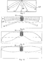
- FIG. 6 shows a plan view of an outdoor lamp 21, which is a street lamp in the illustrated embodiment.
- FIG. 6 shows a plan view of the light exit side of the street lamp 21, wherein a mast 22 to which the lamp 21 attached, is shown in cross section.
- a common board 23 On a common board 23, a plurality of LED lighting devices are mounted, each comprising an LED 1 and a light-guiding body 3, as described above.
- the board is flat in the illustrated embodiment. However, according to alternative embodiments, the board may also be curved along an axis, in particular along the longitudinal axis of the luminaire.
- the plurality of LED illuminators partially have a different spatial arrangement relative to rotation about their respective LED main emission direction.
- the LED lighting devices are arranged symmetrically with respect to a vertical plane through the lamp.
- the LED lighting devices are aligned so that their respective main maxima are each aligned substantially perpendicular to both sides of the vertical plane. This results in a total symmetrical light distribution curve of the luminaire, which in the polar diagram in FIG. 7 is shown.
- the main maxima 13 of all lighting devices are superimposed to two combined main maxima 13 ', which extend symmetrically on both sides of the lamp.
- the secondary maxima 19 are superimposed to a combined secondary maximum 19 ', which is mirror-symmetrical with respect to the vertical plane through the lamp.
- the street lamp 21 are only a part, but preferably the majority of all LED lighting devices oriented so that their main maxima extend opposite to the vertical plane of the luminaire.
- Two further groups 32a and 32b of LED lighting devices are inclined at an angle of + 10 ° and -10 ° with respect to the transverse axis of the lamp.
- Two further groups 33a and 33b are inclined at an angle of + 20 ° and -20 ° with respect to the transverse axis of the lamp.
- the rays of the respective main maximum of the different LED groups are shown.
- the luminous intensity which is directed at the surface to be illuminated, is symmetrical on both sides of the luminaire, but displaced forwards at an angle of approximately ⁇ 15 ° with respect to the transverse axis of the luminaire.
- this Lichtbandknickung can be, for example, a street evenly illuminate over its width, even if the street lamp 21 is mounted on one longitudinal side of the road.
- a multiplicity of luminaires 21, which in each case a Lichtbandknickung, like in the FIG. 9 shown the road can be illuminated almost uniformly over its length and width.
- FIG. 10 FIG. 2 shows the light distribution curve in a cone-crest representation according to FIG. 9
- the LED lighting devices are divided into only two groups, each occupying an angle of 0 ° to the transverse light extension (this corresponds to the group 31, as shown in FIG. 6 is shown).
- Such a luminaire is preferred if only one street side is to be illuminated, as in FIG. 10 shown.
- street lights can also be mounted centrally above the road to illuminate both road halves of the road.
- the invention also provides, in particular, that the LED lighting devices can be variably positioned on the board. This makes it possible in particular different Lichtbandknickitch, as in connection with the FIGS. 9 and 10 described, realized by a luminaire type.
Landscapes
- Engineering & Computer Science (AREA)
- General Engineering & Computer Science (AREA)
- Non-Portable Lighting Devices Or Systems Thereof (AREA)
Description
- Die Erfindung betrifft das Gebiet von Beleuchtungseinrichtungen, deren Lichtquelle durch eine lichtemittierende Diode, kurz LED, gebildet wird, und insbesondere eine LED-Beleuchtungseinrichtung mit einer asymmetrischen Lichtverteilungskurve.
- Ein Beleuchtungssystem mit einem LED-Element und einer Beleuchtungsoptik in Form einer Linse ist in der
DE 101 58 395 A1 offenbart. Um eine möglichst gleichmäßige Beleuchtung auf einer gekrümmten Fläche zu erzeugen, ist gemäß dieser Druckschrift vorgesehen, die Linse mit asymmetrischen gekrümmten Eingangs- und Ausgangsflächen zu versehen. Das von dem LED-Element abgestrahlte Licht wird gegenüber der Hauptabstrahlrichtung des LED-Elements asymmetrisch umgelenkt, um eine gekrümmte Fläche möglichst gleichmäßig zu beleuchten. - Obgleich es durch die in der
DE 101 58 395 A1 offenbarten Beleuchtungseinrichtung möglich ist, das von dem LED-Element abgegebene Licht in eine gewünschte Richtung umzulenken, so eignet sich diese Beleuchtungsoptik dennoch nur zur gleichmäßigen Ausleuchtung verhältnismäßig einfach geformter Flächen. Für komplexere Beleuchtungsaufgabe müßte der Fachmann eine Vielzahl derartiger Beleuchtungseinrichtungen vorsehen, die individuell in unterschiedliche Richtungen mit einer jeweils gewünschten Intensität Licht abgeben. -
DE 103 14 254 A1 offenbart eine Leuchte für Fahrzeuge, insbesondere für Kraftfahrzeuge. Ein Lichtleiterelement, welches auf einer ersten Längsseite eine Lichtaustrittsfläche und eine der ersten Längsseite gegenüberliegende Reflektorfläche aufweist, ist vorgesehen, um Licht einer LED in etwa einer Richtung seitlich zur Hauptabstrahlrichtung der LED umzulenken. In dem Lichtleiterelement wird Lichtstrahlung teilweise direkt durch die Lichtaustrittsfläche ausgekoppelt und teilweise vorher durch Totalreflexion umgelenkt. - Aufgabe der Erfindung ist es, eine LED-Beleuchtungseinrichtung zur Verfügung zu stellen, welche auch für komplexe Beleuchtungsaufgaben geeignet ist.
- Die Erfindung sieht eine Straßenleuchte mit mehreren LED-Beleuchtungseinrichtungen vor, die jeweils wenigstens eine LED mit einer bezüglich einer Hauptabstrahlrichtung der LED vorzugsweise rotationssymmetrischen Lichtabgabe und einen Lichtlenkkörper umfaßt, das aus einem Lichtleiter gebildet ist und wenigstens eine Lichtaustrittsfläche aufweist, wobei Licht der LED in den Lichtlenkkörper eingekoppelt wird und wenigstens ein Teil des Licht so in dem Lichtlenkkörper umgelenkt wird, daß es den Lichtlenkkörper durch die Lichtaustrittsfläche mit einer Lichtverteilung verläßt, die asymmetrisch bezüglich der Hauptabstrahlrichtung der LED ist, wobei die Lichtverteilung in einer Schnittebene, in welcher die Hauptabstrahlrichtung der LED liegt und welche die Lichtaustrittsfläche schneidet, eine Lichtverteilungskurve definiert, die ein Hauptmaximum und wenigstens ein Nebenmaximum aufweist, wobei das Hauptmaximum asymmetrisch bezüglich der Hauptabstrahlrichtung der LED liegt.
- Bei den Lichtlenkkörpern handelt es sich beispielsweise um einen Vollichtleiter, der durchgängig aus einem transparenten Material gebildet ist. In einer alternativen Ausführungsform ist auch ein Hohllichtleiter möglich. Der Vollichtleiter ist beispielsweise aus einem transparenten Material wie Glas oder Kunststoff, z.B. PMMA, PU oder PC, gebildet. Die Lichtlenkung im Lichtlenkkörper erfolgt durch Brechung und/oder durch Reflexion. Bei dem Volllichtleiter ist insbesondere auch Totalreflexion an ausgewählten Grenzflächen möglich. Alternativ können auch Grenzflächen verspiegelt sein, um eine Reflexion zu erzeugen.
- Erfindungsgemäß ist ein Hauptmaximum der Lichtverteilungskurve asymmetrisch bezüglich der Hauptabstrahlrichtung der LED angeordnet. Durch das Hauptmaximum wird die notwendige Leuchtdichte (gemessen in cd/m2) oder Beleuchtungsstärke (gemessen in lx) auf einer zu beleuchtenden Fläche erzeugt, während das Nebenmaximum zur Verbesserung der Gleichmäßigkeit der Leuchtdichte oder Beleuchtungsstärke in andere Raumbereiche gelenkt wird. Durch das asymmetrische Hauptmaximum läßt sich durch Ausrichten die LED-Beleuchtungseinrichtungen für eine vorgegebene Beleuchtungsaufgabe individuell einstellen, wobei das Ausrichten durch ein Drehen der LED-Beleuchtungseinrichtung in der Achse der Hauptabstrahlrichtung der LED erfolgen kann. Das Nebenmaximum dient zur Vergleichmäßigung der Leuchtdichte in den Raumbereichen, die von dem Hauptmaximum der Leuchtstärkeverteilung nicht erreicht werden. Es lassen sich durch das wenigstens eine Nebenmaximum auch Lichtakzente unabhängig von dem Hauptmaximum der Lichtverteilungskurve erzeugen. In einer vereinfachten Ausführungsform der LED-Beleuchtungseinrichtung ist kein Nebenmaximum in der Lichtverteilungskurve vorgesehen.
- Gemäß einer Ausführungsform liegt das Hauptmaximum in der Schnittebene, in der die Achse der Hauptabstrahlrichtung der LED liegt und die das Lichtaustrittsfenster senkrecht schneidet, gegenüber der LED-Hauptabstrahlrichtung in einem Winkelbereich zwischen 45° bis 80°, bevorzugt zwischen 55° und 75°. Das Nebenmaximum liegt vorzugsweise in der Schnittebene gegenüber der LED-Hauptabstrahlrichtung in einem Winkelbereich zwischen -30° und 30°, insbesondere bevorzugt zwischen -20° und 20°. Während das Hauptmaximum asymmetrisch angeordnet ist, ist es bevorzugt, daß das Nebenmaximum einen geringen Winkel zu der LED-Hauptabstrahlrichtung aufweist oder etwa symmetrisch zur LED-Hauptabstrahlrichtung ausgerichtet ist. Diese Anordnung hat den Vorteil, daß beim Drehen der LED-Beleuchtungseinrichtung um die Hauptabstrahlrichtung der LED das Hauptmaximum individuell in eine Richtung gelenkt werden kann, während das Nebenmaximum unabhängig von der Ausrichtung des Hauptmaximums in etwa dem gleichen Raumwinkelbereich verbleibt.
- Vorzugsweise weist der Lichtlenkkörper mehrere Lichtaustrittsflächen auf, wobei gemäß einer bevorzugten Ausführungsform jeweils eine oder mehrere Lichtaustrittsflächen entweder dem Hauptmaximum oder einem Nebenmaximum zugeordnet sind.
- Vorzugsweise sind zwei Lichtaustrittsflächen für das Hauptmaximum vorgesehen. Beispielsweise kann eine Lichtaustrittsfläche ein eng fokussiertes Bündel von Lichtstrahlen ausgeben, während die zweite Lichtaustrittsfläche ein divergentes Bündel von Lichtstrahlen ausgibt. Dadurch läßt sich mit dem Hauptmaximum ein gewünschter Ort punktförmig beleuchten und mit dem divergenten Bündel von Lichtstrahlen die angrenzende Umgebung aufhellen.
- Gemäß einer Ausführungsform weist der Lichtlenkkörper eine oder mehrere Flächen auf, die gegenüber der LED so angeordnet sind, daß ein Teil des Lichts der LED daran total reflektiert wird. Dadurch läßt sich in der Art eines Kanals das Licht zu der gewünschten Lichtaustrittsfläche in dem Lichtlenkkörper leiten. Die Grenzflächen, an denen das Licht total reflektiert wird, können entweder eben oder gewölbt sein. Durch die Wölbung wird das entsprechende Lichtbündel, das an dieser Grenzfläche total reflektiert wird, entweder aufgeweitet oder gebündelt. Alternativ können die Flächen des Lichtlenkkörpers, an denen Lichtstrahlung reflektiert wird, auch verspiegelt sein. Die verspiegelten Flächen können ebenso konkav oder konvex gewölbt sein, um das Lichtbündel aufzuweiten oder zu fokussieren.
- Gemäß einer bevorzugten Ausführungsform weist der Lichtlenkkörper eine oder mehrere Lichteintrittsflächen auf, durch welche das Licht von der LED in den Lichtlenkkörper eingekoppelt wird. Alternativ kann die LED auch in dem Lichtlenkkörper integriert sein. Die mehreren Lichteintrittflächen haben den Vorteil, daß sich das in den Lichtlenkköper einfallende Licht in mehrere Bündel aufteilen läßt, die in dem Lichtlenkkörper in unterschiedliche Richtungen weitergeleitet werden. Insbesondere können die Lichteintrittsflächen auch gewölbt sein, um beim Eintritt des Lichts in den Lichtlenkkörper das entsprechende Strahlenbündel zu fokussieren oder aufzuweiten. Bei einer konvex gekrümmten Lichteintrittsfläche wird durch die Lichtbrechung an der Lichteintrittsfläche das entsprechende Strahlenbündel fokussiert, während bei einer konkaven Lichteintrittsfläche das entsprechende Bündel aufgeweitet wird.
- Gemäß einer Ausführungsform sind eine oder mehrere Lichteintrittsflächen rotationssymmetrisch um die LED-Hauptabstrahlrichtung angeordnet. Bei dieser Ausführungsform kann durch Drehen des Lichtlenkkörper gegenüber der LED die Richtung des Haupt- und Nebenmaximums um die Hauptabstrahlrichtung der LED eingestellt werden, ohne daß die LED mit dem Lichtlenkkörper mitbewegt werden muß. Diese Ausführungsform ist vorteilhaft für Anwendungen, bei denen die LED beispielsweise auf einer elektrischen Platine fest angeordnet ist und der Lichtlenkkörper in verschiedenen Stellungen auf der Platine angeordnet werden kann. Alternativ kann sich die Lichteintrittsfläche wenigstens abschnittsweise auch parallel zu der Lichtaustrittsfläche erstrecken.
- Gemäß einer bevorzugten Ausführungsform wird das Licht der LED beim Einkoppeln in den Lichtlenkkörper durch mehrere Lichteintrittsflächen in wenigstens zwei, bevorzugt drei Lichtbündel aufgeteilt. Diese Lichtbündel können anschließend unabhängig voneinander entweder in Richtung zu dem Hauptmaximum oder zu einem der Nebenmaxima gelenkt werden. Außerdem können die Lichtbündel unabhängig voneinander im Lichtlenkkörper gebündelt oder aufgeweitet werden entweder direkt beim Eintritt durch eine der Lichteintrittsflächen, beim Lichtaustritt durch eine konkav oder konvex gewölbte Lichtaustrittsfläche oder bei einer Totalreflexion innerhalb des Lichtlenkkörpers an einer konkaven oder konvexen Grenzflächen.
- Insbesondere können auch mehrere Lichtlenkbündel in Richtung des Hauptmaximums gelenkt werden und/oder ein oder mehrere Lichtbündel zu dem Nebenmaximum gelenkt werden.
- Gemäß einer Ausführungsform erstreckt sich wenigstens eine Lichtaustrittsfläche in einer Richtung senkrecht zu der genannten Schnittebene gradlinig. Bei dieser Ausführungsform ist die Lichtverteilung des durch die Lichtaustrittsfläche austretenden Lichtbündel spiegelsymmetrisch bezüglich einer Ebene ausgebildet, die senkrecht zur der gradlinigen Längserstreckung der Lichtaustrittsfläche liegt und die Achse der Hauptabstrahlrichtung der LED enthält.
- Gemäß einer Ausführungsform können auch mehrere nicht-parallele Seiten an dem Lichtlenkkörper vorgesehen sein, an denen jeweils wenigstens eine Lichtaustrittsfläche angeordnet ist. Bei einer rechteckigen oder einem etwa quadratischen Grundform des Lichtlenkkörpers lassen sich in vier Richtungen mit einem Azimutalwinkel von 0°, 90°, 180° bzw. 270° bezogen auf die LED-Hauptabstrahlrichtung Maximas in der Lichtverteilungskurve, d.h. entweder Haupt- oder Nebenmaxima, erzeugen. Die Asymmetrie des Hauptmaximums bezüglich der LED-Hauptabstrahlrichtung bleibt dennoch erhalten.Vorzugsweise werden die vorhergehend beschriebenen LED-Beleuchtungseinrichtungen in Straßenleuchten eingesetzt. Das Hauptmaximum in der Lichtverteilungskurve wird zur Ausleuchtung der Fahrbahn genutzt, während das Nebenmaximum die Gleichmäßigkeit der Lichtverteilung auf der Bewertungsfläche verbessert. Durch eine variable Positionierung (insbesondere Drehung) des Lichtlenkkörpers oder der gesamten LED-Beleuchtungseinrichtung um die Hauptabstrahlrichtung der LED kann eine gewünschte Ausstrahlrichtung eingestellt werden.
- Gemäß einem weiteren Aspekt betrifft die Erfindung eine Straßenleuchte mit einer Platine, auf der mehrere LED-Beleuchtungseinrichtungen installiert sind, wobei jede der LED-Beleuchtungseinrichtungen wenigstens eine LED mit einer bezüglich einer Hauptabstrahlrichtung der LED-rotationssymmetrischen Lichtabgabe und einem Lichtlenkkörper umfaßt, der aus einem Lichtleiter gebildet ist und wenigstens eine Lichtaustrittsfläche aufweist, wobei Licht der LED in dem Lichtlenkkörper eingekoppelt wird und der Lichtlenkkörper wenigstens einen Teil des Lichts so umlenkt, daß es den Lichtlenkkörper durch eine Lichtaustrittsfläche mit einer Lichtverteilung verläßt, die asymmetrisch bezüglich der Hauptabstrahlrichtung der LED ist, und die Lichtverteilung in einer Schnittebene, in welcher die Hauptabstrahlrichtung der LED liegt und die Lichteintrittsfläche schneidet, eine Lichtverteilung definiert, die ein Hauptmaximum aufweist, das asymmetrisch bezüglich der Hauptabstrahlrichtung der LED liegt.
- Vorzugsweise umfaßt die Leuchte mehrere gleiche LED-Beleuchtungseinrichtungen nach Ausführungsformen, wie sie vorhergehend beschrieben wurden.
- Die Verwendung von LED Beleuchtungseinrichtungen mit asymmetrischen Hauptmaximum erlaubt es in vorteilhafter Weise die Leuchte für die gewünschte Beleuchtungsaufgabe einzurichten. Insbesondere für Straßenleuchten, welche einen länglichen Abschnitt einer Fahrbahn ausleuchten sollen, sind folgende bevorzugte Ausführungsformen vorgesehen.
- Gemäß einer Ausführungsform umfaßt die Leuchte mehrere Gruppen von LED-Beleuchtungseinrichtungen, deren Hauptmaxima jeweils die gleiche räumliche Orientierung bezüglich ihrer LED-Hauptabstrahlrichtung besitzen.
- Vorzugsweise ist die Orientierung von zwei Gruppen spiegelsymmetrisch bezüglich einer Ebenen angeordnet, welche die Platine senkrecht schneidet. Bei einer auf die Fahrbahn gerichteten Straßenleuchte entspricht das der Vertikalebene der Leuchte quer zur Fahrbahnlängserstreckung.
- Gemäß einer bevorzugten Ausführungsform ist eine erste und eine zweite Gruppe von LED-Beleuchtungseinrichtungen der Leuchte vorgesehen, deren Hauptmaxima jeweils einem Azimutalwinkel gegenüber der LED-Hauptabstrahlrichtung aufweist, die entgegengesetzt zueinander ausgerichtet sind. Diese Ausführungsform einer Leuchte erzeugt eine Lichtverteilung auf der beleuchteten Fläche, wie z.B. die Fahrbahn, die sich symmetrisch zu beiden Seiten der Leuchte erstreckt. Gemäß einer weiteren bevorzugten Ausführungsform ist eine dritte und eine vierte Gruppe von LED-Beleuchtungseinrichtungen in der Leuchte vorgesehen, deren Hauptmaxima einen Winkel zwischen 5° und 30° bzw. zwischen -5° und -30° gegenüber der ersten und zweiten Gruppe bilden. Durch die dritte und vierte Gruppe von LED-Beleuchtungseinrichtungen wird eine Lichtbandknickung erzeugt, die insbesondere für Straßenleuchten von Vorteil ist, die nicht mittig über der Fahrbahn, sondern am Fahrbahnrand angeordnet sind. Durch die Lichtbandknickung wird trotz der Anordnung am Fahrbahnrand die Fahrband in ihrer Breite weitgehend gleichmäßig ausgeleuchtet.
- Gemäß einer weiteren Ausführungsform sind noch weitere Gruppen von LED-Beleuchtungseinrichtungen vorgesehen, die symmetrisch bezüglich der Ebene senkrecht zur Platine, d.h. der Vertikalebene der Leuchte, angeordnet sind. Insbesondere können die LED-Beleuchtungseinrichtungen auch variabel positionierbar in der Leuchte vorgesehen sein.
- Weitere Merkmale und Vorteile der vorliegenden Erfindung werden aus der nachfolgenden Beschreibung einer bevorzugten Ausführungsform deutlich. In den Figuren ist folgendes dargestellt:
- Figur 1
- zeigt eine Schnittdarstellung durch eine LED-Beleuchtungseinrichtung der vorliegenden Erfindung.
- Figur 2
- zeigt eine Aufsicht auf die LED-Beleuchtungseinrichtung der vorliegenden Erfindung.
- Figur 3
- zeigt eine Schnittdarstellung durch die LED-Beleuchtungseinrichtung nach
Figur 1 mit der Schnittebene in der Mittelebenen und mit eingezeichnetem Lichtstrahlengang. - Figur 4
- zeigt schematisch die Lichtverteilungskurve der LED-Beleuchtungseinrichtung in einer Schnittebene entsprechend der
Figuren 1 und3 . - Figur 5
- zeigt eine perspektivische Ansicht eines Lichtlenkkörpers der LED-Beleuchtungseinrichtung.
- Figur 6
- zeigt eine Aufsicht auf die Lichtaustrittsfläche einer Leuchte mit mehreren LED-Beleuchtungseinrichtungen gemäß der vorliegenden Erfindung.
- Figur 7
- zeigt schematisch die Lichtverteilungskurve der Leuchte nach
Figur 6 in einer Polardarstellung. - Figur 8
- zeigt eine Aufsicht auf die Leuchte gemäß
Figur 6 mit eingezeichnetem Lichtstrahlengang entlang der Richtung der Hauptmaxima. - Figur 9
- zeigt die Lichtverteilungskurve einer Leuchte entsprechend der
Figur 7 in einer Kegelmantelkurve auf einer zu beleuchtenden Straße. - Figur 10
- zeigt die Lichtverteilungskurve in einer Kegelmantelkurve auf einer zu beleuchtenden Straße einer alternativen Ausführungsform einer Leuchte.
- Die LED-Beleuchtungseinrichtung weist eine LED 1 auf, die in einer Vertiefung 2 eines Lichtlenkkörpers 3 angeordnet ist. Der Lichtlenkkörper ist in der dargestellten Ausführungsform ein Vollichtleiter, der durchgängig aus einem transparenten Kunststoff (PMMA) gebildet ist.
- Wie in der Aufsicht gemäß
Figur 2 zu sehen ist, weist der Lichtlenkkörper 3 eine Längserstreckung auf (in der Bildebene derFigur 2 die Horizontale), wobei sich die Vertiefung 2 seitlich der LED 1 im wesentlichen in Längsrichtung des Lichtlenkkörpers 3 erstreckt. Wie in der perspektivischen Darstellung nachFigur 5 , welche den Lichtlenkkörper 3 ohne LED zeigt, gut zu sehen ist, ist die Vertiefung 2 auf einer Längsseite ausgeschnitten und auf der gegenüberliegenden Längsseite teilweise kreisförmig ausgebildet. - Die Vertiefung 2 in dem Lichtlenkkörper 3 bildet insgesamt drei Lichteintrittsflächen 5, 6 und 7, welche die LED 1 umgeben. Die der LED in ihrer Hauptabstrahlrichtung gegenüberliegende Lichteintrittsfläche 5 ist konvex gewölbt, während die seitlich der LED 1 angeordneten Lichteintrittsflächen 6 und 7 in einer Schnittebene, in der die Hauptabstrahlrichtung der LED liegt gradlinig sind. Die Schnittebene entspricht der Bildebene der
Figuren 1 und3 . Die LED-Hauptabstrahlrichtung entspricht der Vertikalen in denFiguren 1 und3 . - Wie in der
Figur 3 dargestellt ist, tritt das von der LED 1 ausgehende Licht durch die Lichteintrittsflächen 5, 6 und 7 in den Lichtlenkkörper 3 ein und wird dabei in drei Strahlenbündel 8, 9 und 10 aufgeteilt. Das Strahlenbündel 9, welches entlang der Hauptabstrahlrichtung der LED 1 durch die Lichteintrittsfläche 5 in den Lichtlenkkörper 3 eintritt, wird aufgrund einer konvexen Wölbung der Lichteintrittsfläche 5 beim Lichteintritt durch Lichtbrechung etwas fokussiert. - Im weiteren Verlauf trifft das Strahlenbündel 9 auf eine Grenzfläche 11 des Lichtlenkkörpers 3 auf, die so angeordnet ist, daß das Strahlenbündel 9 totalreflektiert wird. Die Grenzfläche 11 ist ebenfalls etwas konvex gekrümmt, wodurch das Strahlenbündel 9 weiter fokussiert wird. Nach der Totalreflexion an der Grenzfläche 11 verläßt das Strahlenbündel 9 den Lichtlenkkörper durch eine Lichtaustrittsfläche 12. Die Lichtaustrittsfläche 12 ist eben ausgebildet. Das Strahlenbündel 9, das den Lichtlenkkörper etwas fokussiert verläßt, bildet ein Hauptmaximum 13 in der Lichtstärkeverteilung. Das Hauptmaximum 13 liegt in einem Winkelbereich zwischen 45° und 70° bezogen auf die Hauptabstrahlrichtung der LED. Die Polardarstellung der Lichtstärkeverteilung ist in
Figur 4 dargestellt. Die 0°-Vertikale in derFigur 4 schematisch entspricht der Hauptabstrahlrichtung der LED 1. - Ein weiteres Lichtbündel 8 tritt ausgehend von der LED 1 durch die Lichteintrittsfläche 6 in den Lichtlenkkörper ein und verläßt ohne weitere Reflexion den Lichtlenkkörper 3 durch eine ebene Lichtaustrittsfläche 14, die in einem Abstand zu der Lichtaustrittsfläche 12 auf der gleichen Seite des Lichtlenkkörpers angeordnet ist. Das Strahlenbündel 8 weist nach der Brechung an der Lichteintrittsfläche 6 und der Lichtaustrittsfläche 14 eine Richtung auf, die ebenfalls dem Winkelbereich des Hauptmaximums 13 entspricht. Im Unterschied zu dem Strahlenbündel 9 ist das Strahlenbündel 8 jedoch stärker aufgeweitet. In der Lichtstärkeverteilung sorgt das Strahlenbündel 8 für eine Verbreiterung des Hauptmaximums 13. Das Lichtbündel 8 wird etwa durch den Anteil des Lichts der LED 1 gebildet, der ohnehin die LED in Richtung des Hauptmaximums verläßt. Durch die Brechung an der Lichteintrittsfläche 6 und der Lichtaustrittsfläche 14 wird das Lichtbündel 8 nur geringfügig abgelenkt.
- Das dritte Lichtbündel 10 tritt von der LED 1 durch die Lichteintrittsfläche 7 in den Lichtlenkkörper ein und wird an einer ebenen Grenzfläche 15 total reflektiert. Die Grenzfläche 15 ist gegenüber der LED so angeordnet, daß das Licht nach der Totalreflexion die Grenzfläche 15 etwa parallel verläßt. Danach wird das Strahlenbündel 10 durch den Lichtlenkkörper 3 geleitet, der in diesem Bereich eine Art Kanal für das Lichtbündel 10 bildet. Der Kanal wird durch etwa parallele Grenzflächen 16 und 17 des Lichtlenkkörpers 3 gebildet, die sich seitlich versetzt zu der Hauptabstrahlrichtung der LED 1 erstrecken. Beim Auftreffen von Lichtstrahlen auf diese Grenzflächen, beispielsweise die Grenzfläche 16 wie in
Figur 3 dargestellt, wird die Strahlung reflektiert. Schließlich tritt das Lichtbündel 10 durch die Lichtaustrittsfläche 18 aus dem Kanal 16, 17 des Lichtlenkkörpers 3 aus und verläßt diesen in Richtung von etwa +15° bezogen auf die Hauptabstrahlrichtung der LED. Durch das Strahlenbündel 10 wird in der Lichtverteilungskurve, die inFigur 4 dargestellt ist, das Nebenmaximum 19 gebildet. - Das Nebenmaximum 19 ist gegenüber der Hauptabstrahlrichtung der LED weniger abgelenkt als das Hauptmaximum 13. Diese Konfiguration ist besonders günstig für verschiedene Beleuchtungsaufgaben, beispielsweise zur Ausbildung von Straßenbeleuchtung. Das Hauptmaximum 13 kann in Richtung der Fahrbahn ausgerichtet werden, während das Nebenmaximum 19 einen Bereich seitlich der Fahrbahn etwa unterhalb der Straßenleuchte aufhellt. Durch die Asymmetrie des Hauptmaximums 13 ist es durch eine variable Positionierung des LED-Beleuchtungskörpers, d.h. durch eine Drehung des LED-Beleuchtungskörpers um die vertikale Achse, erfindungsgemäß möglich, den Beleuchtungskörper für gewünschte Beleuchtungsaufgaben auszurichten. Dabei ist von Vorteil, daß das Nebenmaximum 19 in einem Winkelbereich von ±20° zur Vertikalen der Beleuchtungseinrichtung liegt, weil es eine Ausleuchtung des Bereichs unterhalb der Leuchte gewährleistet, unabhängig von der azimutalen Ausrichtung des Hauptmaximums 13.
- Um die LED-Beleuchtungseinrichtung in einer Leuchte zu installieren, sind auf einer Oberseite Zapfen 20 vorgesehen, mit deren Hilfe die Beleuchtungseinrichtung in einer Leuchte, beispielsweise an einer Platine, mechanisch befestigt wird. Insbesondere kann der Lichtlenkkörper angeklebt oder angelötet werden. In letzterem Fall ist der Lichtlenkkörper teilweise mit Metall versehen und aus einem hitzebeständigen Material (größer 185°C) gebildet. Insbesondere ist eine variable Positionierung des Lichtlenkkörpers möglich. Dazu ist eine teilweise kreisförmige Zentrierhilfe 4 in der Vertiefung 2 vorgesehen, die formschlüssig mit der LED oder einem anderen gegenüberliegenden Bauelement zusammenwirkt. Die LED 1 kann entweder fest mit dem Lichtlenkkörper 3 verbunden sein oder auf dem gegenüberliegenden Bauelement der Leuchte befestigt sein.
- Die in den Figuren dargestellte Ausführungsform des Beleuchtungskörpers weist in der Aufsicht, wie sie in der
Figur 2 dargestellt ist, eine etwa rechteckige Grundform auf, wobei die Lichtaustrittsflächen 12 und 14 Teile eines zackenartigen Profils auf einer Seite bilden. - Gemäß anderen Ausführungsformen können Lichtaustrittsflächen an gegenüberliegenden Seiten des Beleuchtungskörpers vorgesehen sein. Ferner können gemäß einer alternativen Ausführungsform auch Lichtaustrittsflächen an nicht gegenüberliegenden Seiten des Lichtaustrittskörpers vorgesehen sein. Beispielsweise kann der Lichtaustrittskörper eine etwa quadratische Grundform aufweisen und Lichtaustrittsflächen sind an allen vier Seitenflächen gebildet. Diese Ausführungsformen erzeugen mehrere asymmetrische Hauptmaxima, die bezüglich der Hauptabstrahlrichtung der LED in einem unterschiedlichen Azimutalwinkelbereich ausgerichtet sind.
- Weitere Ausführungsformen der LED-Beleuchtungseinrichtung sind im Rahmen der Erfindung möglich. Beispielsweise kann der Lichtlenkkörper auch in Form eines Hohllichtleiters ausgebildet sein, wobei die vorhergehend beschriebenen Grenzflächen durch nach innen verspiegelte Wände des Hohllichtleiters gebildet werden.
- Gemäß einer weiteren Ausführungsform umfaßt der LED-Beleuchtungskörper mehrere LEDs. Diese sind beispielsweise in einer Reihe parallel zur Längserstreckung der Lichtaustrittsfenster, d.h. senkrecht zur Bildebene der
Figuren 1 und3 angeordnet. Bei dieser Ausführungsform erstrecken sich die Grenzflächen und die Lichtaustrittsflächen des Lichtlenkkörpers gradlinig parallel zu der in einer Reihe angeordneten LEDs. Insbesondere können LEDs unterschiedlicher Farbe in einem LED-Beleuchtungskörper kombiniert sein, beispielsweise um weißes Licht zu erzeugen. - Gemäß einem weiteren Aspekt der Erfindung sind eine Vielzahl der vorhergehend beschriebenen Beleuchtungskörper in einer Leuchte, wie sie in
Figur 6 dargestellt ist, kombiniert. DieFigur 6 zeigt eine Aufsicht auf eine Außenleuchte 21, wobei es sich in der dargestellten Ausführungsform um eine Straßenleuchte handelt. - Die
Figur 6 zeigt eine Aufsicht auf die Lichtaustrittsseite der Straßenleuchte 21, wobei ein Mast 22, an dem die Leuchte 21 angebracht, im Querschnitt dargestellt ist. Auf einer gemeinsamen Platine 23 sind eine Vielzahl von LED-Beleuchtungseinrichtungen angebracht, die jeweils ein LED 1 und einen Lichtlenkkörper 3, wie vorhergehend beschrieben, umfassen. Die Platine ist in der dargestellten Ausführungsform eben ausgeführt. Gemäß alternativen Ausführungsformen kann die Platine jedoch auch entlang einer Achse, insbesondere entlang der Längsachse der Leuchte, gekrümmt sein. - Die Vielzahl von LED-Beleuchtungseinrichtungen besitzt teilweise eine unterschiedliche räumliche Anordnung bezüglich einer Drehung um ihre jeweilige LED-Hauptabstrahlrichtung. Die LED-Beleuchtungseinrichtungen sind bezüglich einer Vertikalebene durch die Leuchte symmetrisch angeordnet. Die LED-Beleuchtungseinrichtungen sind dabei so ausgerichtet, daß ihre jeweiligen Hauptmaxima im wesentlichen jeweils senkrecht zu beiden Seiten der Vertikalebene ausgerichtet sind. Dadurch ergibt sich insgesamt eine symmetrische Lichtverteilungskurve der Leuchte, die im Polardiagramm in
Figur 7 dargestellt ist. Die Hauptmaxima 13 aller Beleuchtungseinrichtungen überlagern sich dabei zu zwei kombinierten Hauptmaxima 13', die sich zu beiden Seiten der Leuchte symmetrisch erstrecken. Die Nebenmaxima 19 überlagern sich zu einem kombinierten Nebenmaximum 19', das spiegelsymmetrisch bezüglich der vertikalen Ebene durch die Leuchte ist. - Gemäß der in
Figur 6 dargestellten Ausführungsform der Straßenleuchte 21 sind nur ein Teil, vorzugsweise jedoch der überwiegende Teil, aller LED-Beleuchtungseinrichtungen so orientiert, daß sich ihre Hauptmaxima entgegengesetzt bezüglich der Vertikalebene der Leuchte erstrecken. Dies trifft nur für die Gruppen 31a und 31b von LED-Beleuchtungseinrichtungen zu. Diese sind mit jeweils 0° gegenüber einer Achse quer zur Leuchtenlängsachse ausgerichtet. Zwei weitere Gruppen 32a und 32b von LED-Beleuchtungseinrichtungen sind mit einem Winkel von +10° bzw. -10° gegenüber der Leuchtenquerachse geneigt. Noch zwei weitere Gruppen 33a und 33b ist mit einem Winkel von +20° bzw. -20° gegenüber der Leuchtenquerachse geneigt. In derFigur 8 sind die Strahlen des jeweiligen Hauptmaximums der unterschiedlichen LED-Gruppen dargestellt. Wie in der Aufsicht zu sehen ist, erstrecken sich zu beiden Seiten der Leuchten jeweils drei Strahlenbündel, die einen Winkel von 0°, ±10° bzw. ±20° gegenüber der Leuchtenquerachse einnehmen. Daraus ergibt sich eine Lichtkurvenverteilung auf einer zu beleuchtenden Fläche, die als Kegelmantelkurve (d.h. eine Polardarstellung der Lichtstärke entlang des Schnitts eines Kegelmantels mit einem vorgegebenen Öffnungswinkel um die Vertikale der Leuchte) in derFigur 9 dargestellt ist. Die Besonderheit der Lichtverteilungskurve ist die Lichtbandknickung, die durch die Gruppen 32a,b und 33a,b der LED-Beleuchtungskörper erzielt wird. Die Lichtstärke, die auf der zu beleuchtenden Fläche gerichtet wird, ist zu beiden Seiten der Leuchte symmetrisch, jedoch mit einem Winkel von etwa ±15° bezüglich der Leuchtenquerachse nach vorne verlagert. Durch diese Lichtbandknickung läßt sich beispielsweise eine Straße gleichmäßig über ihre Breite beleuchten, auch wenn die Straßenleuchte 21 an einer Längsseite der Straße montiert ist. Durch eine Vielzahl von Leuchten 21, die jeweils eine Lichtbandknickung, wie in derFigur 9 dargestellt, aufweisen, kann die Straße über ihre Länge und Breite nahezu gleichmäßig ausgeleuchtet werden. - Die
Figur 10 zeigt die Lichtverteilungskurve in einer Kegelmantelkurvendarstellung entsprechend derFigur 9 , jedoch für eine alternative Ausführungsform der Leuchte, bei der die LED-Beleuchtungseinrichtungen in nur zwei Gruppen eingeteilt sind, die jeweils einen Winkel von 0° zur Leuchtenquererstreckung einnehmen (dies entspricht der Gruppe 31, wie sie inFigur 6 dargestellt ist). Eine derartige Leuchte ist bevorzugt, wenn nur eine Straßenseite beleuchtet werden soll, wie inFigur 10 dargestellt. Alternativ können derartige Straßenleuchten auch mittig über der Fahrbahn angebracht werden, um beide Fahrbahnhälften der Straße zu beleuchten. - Die Erfindung sieht es insbesondere auch vor, daß die LED-Beleuchtungseinrichtungen auf der Platine variabel positionierbar sind. Dadurch lassen sich insbesondere unterschiedliche Lichtbandknickungen, wie im Zusammenhang mit den
Figuren 9 und 10 beschrieben, durch einen Leuchtentyp realisieren. -
- 1
- LED
- 2
- Vertiefung
- 3
- Lichtlenkkörper
- 4
- Zentrierhilfe
- 5
- Lichteintrittsfläche
- 6
- Lichteintrittsfläche
- 7
- Lichteintrittsfläche
- 8
- Strahlenbündel
- 9
- Strahlenbündel
- 10
- Strahlenbündel
- 11
- Grenzfläche
- 12
- Lichtaustrittsfläche
- 13
- Hauptmaximum
- 13'
- kombiniertes Hauptmaximum
- 14
- Lichtaustrittsfläche
- 15
- Grenzfläche
- 16
- Grenzfläche
- 17
- Grenzfläche
- 18
- Lichtaustrittsfläche
- 19
- Nebenmaximum
- 19'
- kombiniertes Nebenmaximum
- 20
- Zapfen
- 21
- Straßenleuchte
- 22
- Mast
- 23
- Platine
- 31a,b
- Gruppe von LED-Beleuchtungseinrichtungen
- 32a,b
- Gruppe von LED-Beleuchtungseinrichtungen
- 33a,b
- Gruppe von LED-Beleuchtungseinrichtungen
Claims (15)
- Straßenleuchte mit mehreren LED-Beleuchtungseinrichtungen, die jeweils wenigstens eine LED (1) mit einer Hauptabstrahlrichtung in der Lichtabgabe der LED und einen Lichtlenkkörper (3) umfaßt, der aus einem Lichtleiter gebildet ist und wenigstens eine Lichtaustrittsfläche (12, 14, 18) aufweist,
wobei Licht der LED (1) in den Lichtlenkkörper (3) eingekoppelt wird und der Lichtlenkkörper (3) wenigstens einen Teil des Lichts so umlenkt, daß es den Lichtlenkkörper (3) durch die Lichtaustrittsfläche (12, 14, 18) mit einer Lichtverteilung verläßt, die asymmetrisch bezüglich der Hauptabstrahlrichtung der LED ist,
wobei die Lichtverteilung in einer Schnittebene, in welcher die Hauptabstrahlrichtung der LED liegt und welche die Lichtaustrittsfläche (12, 14, 18) schneidet, eine Lichtverteilungskurve definiert, die ein Hauptmaximum (13) und wenigstens ein Nebenmaximum aufweist, wobei das Hauptmaximum (13) asymmetrisch bezüglich der Hauptabstrahlrichtung der LED liegt. - Straßenleuchte nach Anspruch 1, wobei das Hauptmaximum (13) in der Schnittebene gegenüber der LED-Hauptabstrahlrichtung in einem Winkelbereich zwischen 45° bis 80°, bevorzugt zwischen 55° und 75°, liegt, und/oder das Nebenmaximum (19) in der Schnittebene gegenüber der LED-Hauptabstrahlrichtung in einem Winkelbereich zwischen -30° und 30°, bevorzugt zwischen -20° und 20°, liegt.
- Straßenleuchte nach einem der vorhergehenden Ansprüche, wobei der Anteil des Lichts, der den Lichtlenkkörper (3) in Richtung des Hauptmaximums (13) verläßt, und der Anteil des Lichts, der den Lichtlenkkörper in Richtung des Nebenmaximums (19) verläßt, durch unterschiedliche Lichtaustrittsflächen (12, 14, 18) des Lichtlenkkörpers (3) hindurchtreten.
- Straßenleuchte nach einem der vorhergehenden Ansprüche, wobei der Anteil des Lichts, welcher den Lichtlenkkörper (3) in Richtung des Hauptmaximums verläßt, den Lichtlenkkörper durch wenigstens zwei unterschiedliche Lichtaustrittsflächen (12, 14) des Lichtlenkkörpers (3) verläßt.
- Straßenleuchte nach einem der vorhergehenden Ansprüche, wobei der Lichtlenkkörper ein oder mehrere Flächen (11, 15, 16) aufweist, die gegenüber der LED so angeordnet sind, daß Licht der LED daran total reflektiert wird.
- Straßenleuchte nach einem der vorhergehenden Ansprüche, wobei das Licht der LED durch eine oder mehrere Lichteintrittsflächen (5, 6, 7) in den Lichtlenkkörper (3) eingekoppelt wird.
- Straßenleuchte nach Anspruch 6, wobei die eine oder mehreren Lichteintrittsflächen rotationssymmetrisch um die LED-Hauptabstrahlrichtung oder wenigstens abschnittsweise parallel zu wenigstens einer Lichtaustrittsfläche (12, 14, 18) angeordnet ist bzw. sind.
- Straßenleuchte nach Anspruch 6 oder 7, wobei das Licht der LED beim Einkoppeln durch mehrere Lichteintrittsflächen (5; 6; 7) in wenigstens zwei, bevorzugt drei Lichtbündel aufgeteilt wird, wobei insbesondere eines oder mehrere der Lichtbündel (8, 9) durch den Lichtlenkkörper in Richtung des Hauptmaximums (13) gelenkt werden und eines oder mehrere der anderen Lichtbündel (10) in Richtung des Nebenmaximums (19) gelenkt werden.
- Straßenleuchte nach einem der vorhergehenden Ansprüche, wobei die wenigstens eine Lichtaustrittsfläche (12, 14, 18) sich in der Richtung senkrecht zur besagten Schnittebene gradlinig erstreckt.
- Straßenleuchte nach einem der vorhergehenden Ansprüche, wobei mehrere LEDs vorgesehen sind, die insbesondere in einer Reihe, insbesondere senkrecht zu besagter Schnittebene, angeordnet sind.
- Straßenleuchte nach einem der vorhergehenden Ansprüche, wobei der Lichtlenkkörper nicht-parallele Seiten aufweist, an denen Lichtaustrittsflächen angeordnet sind.
- Straßenleuchte mit einer Platine (23), auf der mehrere LED-Beleuchtungseinrichtungen installiert sind, wobei jede der LED-Beleuchtungseinrichtungen wenigstens eine LED (1) mit einer bezüglich einer Hauptabstrahlrichtung der LED rotationssymmetrischen Lichtabgabe und jeweils einem Lichtlenkkörper (3) umfaßt, der aus einem Lichtleiter gebildet ist und wenigstens eine Lichtaustrittsfläche (12, 14, 18) aufweist, wobei Licht der LED (1) in den Lichtlenkkörper (3) eingekoppelt wird und der Lichtlenkkörper (3) wenigstens einen Teil des Lichts so umlenkt, daß es den Lichtlenkkörper (3) durch eine Lichtaustrittsfläche (12, 14, 18) mit einer Lichtverteilung verläßt, die asymmetrisch bezüglich der Hauptabstrahlrichtung der LED ist, wobei die Lichtverteilung in einer Schnittebene, in welcher die Hauptabstrahlrichtung der LED liegt und welche die Lichtaustrittsfläche (12, 14, 18) schneidet, eine Lichtverteilungskurve definiert, die ein Hauptmaximum (13) aufweist, das asymmetrisch bezüglich der Hauptabstrahlrichtung der LED liegt.
- Straßenleuchte nach Anspruch 12, wobei die mehreren LED-Beleuchtungseinrichtungen zwei oder mehr Gruppen (31a, 31b, 32a, 32b, 33a, 33b) von LED-Beleuchtungseinrichtungen umfassen, deren Hauptmaxima jeweils die gleiche räumliche Orientierung bezüglich ihrer jeweiligen LED-Hauptabstrahlrichtung besitzen, wobei insbesondere die räumliche Orientierung von zwei der Gruppen (31a, 31b; 32a, 32b; 33a, 33b) von LED-Beleuchtungseinrichtungen spiegelsymmetrisch bezüglich einer Ebene ist, welche die Platine (23) der Leuchte senkrecht schneidet.
- Straßenleuchte nach Anspruch 13, die eine erste und eine zweite Gruppe (31a, 31b) von LED-Beleuchtungseinrichtungen aufweist, deren Hauptmaxima jeweils einen Azimutalwinkel bezüglich ihrer jeweiligen LED-Hauptabstrahlrichtung aufweisen, so daß die Hauptmaxima der beiden Gruppen bezüglich der azimutalen Winkelausrichtung entgegengesetzt zueinander orientiert sind.
- Straßenleuchte nach Anspruch 14, die weiter eine dritte und eine vierte Gruppe (32a, 32b) von LED-Beleuchtungseinrichtungen aufweisen, wobei die Hauptmaxima der dritten Gruppe (32a) einen einheitlichen Azimutalwinkel bezüglich der LED-Hauptabstrahlrichtung zwischen 5° und 30° gegenüber den Hauptmaxima der ersten Gruppe einnehmen und die vierte Gruppe (32b) einen einheitlichen Azimutalwinkel bezüglich der LED-Hauptabstrahlrichtung zwischen -5° und -30° gegenüber der zweiten Gruppe einnehmen.
Applications Claiming Priority (1)
| Application Number | Priority Date | Filing Date | Title |
|---|---|---|---|
| DE102007044893 | 2007-09-20 |
Publications (3)
| Publication Number | Publication Date |
|---|---|
| EP2039985A2 EP2039985A2 (de) | 2009-03-25 |
| EP2039985A3 EP2039985A3 (de) | 2013-09-04 |
| EP2039985B1 true EP2039985B1 (de) | 2017-10-25 |
Family
ID=40122496
Family Applications (1)
| Application Number | Title | Priority Date | Filing Date |
|---|---|---|---|
| EP08016580.6A Active EP2039985B1 (de) | 2007-09-20 | 2008-09-19 | LED-Beleuchtungseinrichtung mit asymmetrischer Lichtverteilung, insbesondere für Straßenleuchten |
Country Status (1)
| Country | Link |
|---|---|
| EP (1) | EP2039985B1 (de) |
Families Citing this family (16)
| Publication number | Priority date | Publication date | Assignee | Title |
|---|---|---|---|---|
| US7891835B2 (en) | 2008-07-15 | 2011-02-22 | Ruud Lighting, Inc. | Light-directing apparatus with protected reflector-shield and lighting fixture utilizing same |
| EP2233826B1 (de) * | 2009-03-17 | 2015-12-16 | Thorn Europhane S.A. | Beleuchtungseinheit und Straßenleuchte und/oder Straßenbeleuchtung |
| DE202009006261U1 (de) * | 2009-04-29 | 2010-09-16 | Zumtobel Lighting Gmbh | LED-Leuchte |
| DE102009021182A1 (de) * | 2009-05-13 | 2010-11-18 | Hella Kgaa Hueck & Co. | Beleuchtungsvorrichtung für Straßen |
| DE102009021208A1 (de) * | 2009-05-13 | 2010-11-18 | Hella Kgaa Hueck & Co. | Beleuchtungsvorrichtung für Straßen |
| FR2958997B1 (fr) * | 2010-04-15 | 2012-07-06 | Force Et Lumiere Electr Soc D | Composant et agencement optiques pour un dispositif d'eclairage, en particulier une lanterne de candelabre |
| CN102588876B (zh) * | 2011-01-14 | 2016-02-10 | 欧司朗股份有限公司 | 透镜和具有该透镜的照明装置 |
| DE102011085291B4 (de) * | 2011-07-08 | 2021-02-25 | Zumtobel Lighting Gmbh | Lichtbeeinflussungselement zur Beeinflussung der Lichtabgabe von im Wesentlichen punktförmigen Lichtquellen |
| DE102011079404A1 (de) | 2011-07-19 | 2013-01-24 | Zumtobel Lighting Gmbh | Anordnung zur Lichtabgabe |
| EP2592334B1 (de) | 2011-11-10 | 2014-01-08 | Hella KGaA Hueck & Co. | Beleuchtung für einen Parkplatz |
| US8974077B2 (en) | 2012-07-30 | 2015-03-10 | Ultravision Technologies, Llc | Heat sink for LED light source |
| DE102013207663A1 (de) * | 2013-04-26 | 2014-10-30 | Zumtobel Lighting Gmbh | LED-Leuchte mit unterschiedlich einstellbaren Lichtverteilungen |
| DE202013103401U1 (de) | 2013-07-29 | 2013-08-16 | Stührenberg GmbH Elektrobau-Signaltechnik | Freiformoptik für LED-Straßenleuchten |
| NL2012030C2 (en) * | 2013-12-27 | 2015-06-30 | Orga B V | Beacon light optic, beacon light. |
| DE102014102697A1 (de) * | 2014-02-28 | 2015-09-03 | Murrelektronik Gmbh | Lichtleitendes Bauteil sowie Feldbusmodul |
| NL2035514B1 (en) * | 2023-07-31 | 2025-02-11 | Orga Holding B V | Beacon Light optic |
Family Cites Families (3)
| Publication number | Priority date | Publication date | Assignee | Title |
|---|---|---|---|---|
| DE10158395B4 (de) * | 2001-11-28 | 2011-07-07 | OSRAM Opto Semiconductors GmbH, 93055 | LED-Beleuchtungssystem |
| DE10314254A1 (de) * | 2003-03-29 | 2004-10-07 | Hella Kg Hueck & Co. | Leuchte für Fahrzeuge |
| DE102006008191B4 (de) * | 2006-02-22 | 2015-10-08 | Hella Kgaa Hueck & Co. | Leuchteneinheit für Fahrzeuge |
-
2008
- 2008-09-19 EP EP08016580.6A patent/EP2039985B1/de active Active
Non-Patent Citations (1)
| Title |
|---|
| None * |
Also Published As
| Publication number | Publication date |
|---|---|
| EP2039985A2 (de) | 2009-03-25 |
| EP2039985A3 (de) | 2013-09-04 |
Similar Documents
| Publication | Publication Date | Title |
|---|---|---|
| EP2039985B1 (de) | LED-Beleuchtungseinrichtung mit asymmetrischer Lichtverteilung, insbesondere für Straßenleuchten | |
| EP2719940B1 (de) | Lichtmodul | |
| DE102012202508B4 (de) | Lichtleitervorrichtung für eine Kraftfahrzeugleuchte | |
| EP2058581B1 (de) | LED-Leuchte zur Gestaltung der Lichtstärkeverteilung | |
| DE102013212355B4 (de) | Kraftfahrzeugbeleuchtungseinrichtung mit einem eine Einkoppeloptik und eine Transport- und Umformoptik aufweisenden Lichtleiter | |
| EP2857740B1 (de) | Kfz-Beleuchtungseinrichtung | |
| DE10231326A1 (de) | Leuchteinheit für Fahrzeuge | |
| DE102011085314B3 (de) | Lichtmodul einer Beleuchtungseinrichtung eines Kraftfahrzeugs | |
| DE102007023076B4 (de) | Beleuchtungseinrichtung für Kraftfahrzeuge | |
| WO2015086307A1 (de) | Kraftfahrzeugbeleuchtungseinrichtung | |
| DE102012214138B4 (de) | Lichtmodul einer Kfz-Beleuchtungseinrichtung mit Linsenelement und Reflektor | |
| DE102017115899A1 (de) | Kraftfahrzeugleuchte und Kraftfahrzeugscheinwerfer mit einer solchen Leuchte | |
| DE10109357A1 (de) | Beleuchtungseinrichtung für Fahrzeuge | |
| EP3165818B1 (de) | Innen- oder aussenleuchte, insbesondere strassenleuchte, mit verlagerbarer freiformlinse | |
| DE10231325A1 (de) | Beleuchtungseinrichtung für Fahrzeuge | |
| DE112013005281T5 (de) | Optisches Element mit einem TIR-Flächenabschnitt für verbesserte räumliche Lichtverteilung | |
| DE10000992A1 (de) | Beleuchtungseinrichtung | |
| EP2957827A1 (de) | Optikelement, insbesondere für eine Straßenleuchte, und Straßenleuchte mit einem Optikelement | |
| WO2007088157A1 (de) | Optische linse und beleuchtungseinrichtung mit lichtquelle und optischer linse | |
| DE20317444U1 (de) | Beleuchtungsvorrichtung, insbesondere für Straßen, Wege, Plätze o.dgl. | |
| DE4312889B4 (de) | Vorwiegend direkt strahlende Leuchte mit einem abgehängten Lichtleitkörper | |
| EP3477193A1 (de) | Abdeckung für ein leuchtmodul und leuchtmodul | |
| DE102014212508B4 (de) | Lichtleiteranordnung | |
| EP2348250B1 (de) | Linienförmige LED-Leuchte, insbesondere LED-Ringleuchte | |
| DE10011378A1 (de) | Hohllichtleiterleuchte mit indirekter Lichtabstrahlung |
Legal Events
| Date | Code | Title | Description |
|---|---|---|---|
| PUAI | Public reference made under article 153(3) epc to a published international application that has entered the european phase |
Free format text: ORIGINAL CODE: 0009012 |
|
| AK | Designated contracting states |
Kind code of ref document: A2 Designated state(s): AT BE BG CH CY CZ DE DK EE ES FI FR GB GR HR HU IE IS IT LI LT LU LV MC MT NL NO PL PT RO SE SI SK TR |
|
| AX | Request for extension of the european patent |
Extension state: AL BA MK RS |
|
| RAP1 | Party data changed (applicant data changed or rights of an application transferred) |
Owner name: SITECO BELEUCHTUNGSTECHNIK GMBH |
|
| PUAL | Search report despatched |
Free format text: ORIGINAL CODE: 0009013 |
|
| AK | Designated contracting states |
Kind code of ref document: A3 Designated state(s): AT BE BG CH CY CZ DE DK EE ES FI FR GB GR HR HU IE IS IT LI LT LU LV MC MT NL NO PL PT RO SE SI SK TR |
|
| AX | Request for extension of the european patent |
Extension state: AL BA MK RS |
|
| RIC1 | Information provided on ipc code assigned before grant |
Ipc: F21V 7/00 20060101ALI20130726BHEP Ipc: F21S 8/08 20060101AFI20130726BHEP Ipc: F21Y 101/02 20060101ALN20130726BHEP Ipc: F21V 5/04 20060101ALI20130726BHEP Ipc: F21S 8/10 20060101ALI20130726BHEP |
|
| 17P | Request for examination filed |
Effective date: 20140304 |
|
| RBV | Designated contracting states (corrected) |
Designated state(s): AT BE BG CH CY CZ DE DK EE ES FI FR GB GR HR HU IE IS IT LI LT LU LV MC MT NL NO PL PT RO SE SI SK TR |
|
| AKX | Designation fees paid |
Designated state(s): AT BE BG CH CY CZ DE DK EE ES FI FR GB GR HR HU IE IS IT LI LT LU LV MC MT NL NO PL PT RO SE SI SK TR |
|
| RIC1 | Information provided on ipc code assigned before grant |
Ipc: F21S 8/08 20060101AFI20170329BHEP Ipc: F21S 8/10 20060101ALI20170329BHEP Ipc: F21V 7/00 20060101ALI20170329BHEP Ipc: F21V 5/04 20060101ALI20170329BHEP |
|
| GRAP | Despatch of communication of intention to grant a patent |
Free format text: ORIGINAL CODE: EPIDOSNIGR1 |
|
| INTG | Intention to grant announced |
Effective date: 20170522 |
|
| GRAS | Grant fee paid |
Free format text: ORIGINAL CODE: EPIDOSNIGR3 |
|
| GRAA | (expected) grant |
Free format text: ORIGINAL CODE: 0009210 |
|
| AK | Designated contracting states |
Kind code of ref document: B1 Designated state(s): AT BE BG CH CY CZ DE DK EE ES FI FR GB GR HR HU IE IS IT LI LT LU LV MC MT NL NO PL PT RO SE SI SK TR |
|
| REG | Reference to a national code |
Ref country code: GB Ref legal event code: FG4D Free format text: NOT ENGLISH |
|
| REG | Reference to a national code |
Ref country code: CH Ref legal event code: EP |
|
| REG | Reference to a national code |
Ref country code: AT Ref legal event code: REF Ref document number: 940273 Country of ref document: AT Kind code of ref document: T Effective date: 20171115 |
|
| REG | Reference to a national code |
Ref country code: IE Ref legal event code: FG4D Free format text: LANGUAGE OF EP DOCUMENT: GERMAN |
|
| REG | Reference to a national code |
Ref country code: DE Ref legal event code: R096 Ref document number: 502008015687 Country of ref document: DE |
|
| REG | Reference to a national code |
Ref country code: CH Ref legal event code: NV Representative=s name: ISLER AND PEDRAZZINI AG, CH |
|
| REG | Reference to a national code |
Ref country code: NL Ref legal event code: MP Effective date: 20171025 |
|
| REG | Reference to a national code |
Ref country code: LT Ref legal event code: MG4D |
|
| PG25 | Lapsed in a contracting state [announced via postgrant information from national office to epo] |
Ref country code: NL Free format text: LAPSE BECAUSE OF FAILURE TO SUBMIT A TRANSLATION OF THE DESCRIPTION OR TO PAY THE FEE WITHIN THE PRESCRIBED TIME-LIMIT Effective date: 20171025 |
|
| PG25 | Lapsed in a contracting state [announced via postgrant information from national office to epo] |
Ref country code: NO Free format text: LAPSE BECAUSE OF FAILURE TO SUBMIT A TRANSLATION OF THE DESCRIPTION OR TO PAY THE FEE WITHIN THE PRESCRIBED TIME-LIMIT Effective date: 20180125 Ref country code: LT Free format text: LAPSE BECAUSE OF FAILURE TO SUBMIT A TRANSLATION OF THE DESCRIPTION OR TO PAY THE FEE WITHIN THE PRESCRIBED TIME-LIMIT Effective date: 20171025 Ref country code: SE Free format text: LAPSE BECAUSE OF FAILURE TO SUBMIT A TRANSLATION OF THE DESCRIPTION OR TO PAY THE FEE WITHIN THE PRESCRIBED TIME-LIMIT Effective date: 20171025 Ref country code: ES Free format text: LAPSE BECAUSE OF FAILURE TO SUBMIT A TRANSLATION OF THE DESCRIPTION OR TO PAY THE FEE WITHIN THE PRESCRIBED TIME-LIMIT Effective date: 20171025 Ref country code: FI Free format text: LAPSE BECAUSE OF FAILURE TO SUBMIT A TRANSLATION OF THE DESCRIPTION OR TO PAY THE FEE WITHIN THE PRESCRIBED TIME-LIMIT Effective date: 20171025 |
|
| PG25 | Lapsed in a contracting state [announced via postgrant information from national office to epo] |
Ref country code: BG Free format text: LAPSE BECAUSE OF FAILURE TO SUBMIT A TRANSLATION OF THE DESCRIPTION OR TO PAY THE FEE WITHIN THE PRESCRIBED TIME-LIMIT Effective date: 20180125 Ref country code: IS Free format text: LAPSE BECAUSE OF FAILURE TO SUBMIT A TRANSLATION OF THE DESCRIPTION OR TO PAY THE FEE WITHIN THE PRESCRIBED TIME-LIMIT Effective date: 20180225 Ref country code: HR Free format text: LAPSE BECAUSE OF FAILURE TO SUBMIT A TRANSLATION OF THE DESCRIPTION OR TO PAY THE FEE WITHIN THE PRESCRIBED TIME-LIMIT Effective date: 20171025 Ref country code: LV Free format text: LAPSE BECAUSE OF FAILURE TO SUBMIT A TRANSLATION OF THE DESCRIPTION OR TO PAY THE FEE WITHIN THE PRESCRIBED TIME-LIMIT Effective date: 20171025 Ref country code: GR Free format text: LAPSE BECAUSE OF FAILURE TO SUBMIT A TRANSLATION OF THE DESCRIPTION OR TO PAY THE FEE WITHIN THE PRESCRIBED TIME-LIMIT Effective date: 20180126 |
|
| REG | Reference to a national code |
Ref country code: DE Ref legal event code: R097 Ref document number: 502008015687 Country of ref document: DE |
|
| PG25 | Lapsed in a contracting state [announced via postgrant information from national office to epo] |
Ref country code: DK Free format text: LAPSE BECAUSE OF FAILURE TO SUBMIT A TRANSLATION OF THE DESCRIPTION OR TO PAY THE FEE WITHIN THE PRESCRIBED TIME-LIMIT Effective date: 20171025 Ref country code: SK Free format text: LAPSE BECAUSE OF FAILURE TO SUBMIT A TRANSLATION OF THE DESCRIPTION OR TO PAY THE FEE WITHIN THE PRESCRIBED TIME-LIMIT Effective date: 20171025 Ref country code: EE Free format text: LAPSE BECAUSE OF FAILURE TO SUBMIT A TRANSLATION OF THE DESCRIPTION OR TO PAY THE FEE WITHIN THE PRESCRIBED TIME-LIMIT Effective date: 20171025 Ref country code: CY Free format text: LAPSE BECAUSE OF FAILURE TO SUBMIT A TRANSLATION OF THE DESCRIPTION OR TO PAY THE FEE WITHIN THE PRESCRIBED TIME-LIMIT Effective date: 20171025 Ref country code: CZ Free format text: LAPSE BECAUSE OF FAILURE TO SUBMIT A TRANSLATION OF THE DESCRIPTION OR TO PAY THE FEE WITHIN THE PRESCRIBED TIME-LIMIT Effective date: 20171025 |
|
| PG25 | Lapsed in a contracting state [announced via postgrant information from national office to epo] |
Ref country code: PL Free format text: LAPSE BECAUSE OF FAILURE TO SUBMIT A TRANSLATION OF THE DESCRIPTION OR TO PAY THE FEE WITHIN THE PRESCRIBED TIME-LIMIT Effective date: 20171025 Ref country code: RO Free format text: LAPSE BECAUSE OF FAILURE TO SUBMIT A TRANSLATION OF THE DESCRIPTION OR TO PAY THE FEE WITHIN THE PRESCRIBED TIME-LIMIT Effective date: 20171025 |
|
| PLBE | No opposition filed within time limit |
Free format text: ORIGINAL CODE: 0009261 |
|
| STAA | Information on the status of an ep patent application or granted ep patent |
Free format text: STATUS: NO OPPOSITION FILED WITHIN TIME LIMIT |
|
| REG | Reference to a national code |
Ref country code: FR Ref legal event code: PLFP Year of fee payment: 11 |
|
| PG25 | Lapsed in a contracting state [announced via postgrant information from national office to epo] |
Ref country code: MT Free format text: LAPSE BECAUSE OF FAILURE TO SUBMIT A TRANSLATION OF THE DESCRIPTION OR TO PAY THE FEE WITHIN THE PRESCRIBED TIME-LIMIT Effective date: 20171025 |
|
| 26N | No opposition filed |
Effective date: 20180726 |
|
| PG25 | Lapsed in a contracting state [announced via postgrant information from national office to epo] |
Ref country code: SI Free format text: LAPSE BECAUSE OF FAILURE TO SUBMIT A TRANSLATION OF THE DESCRIPTION OR TO PAY THE FEE WITHIN THE PRESCRIBED TIME-LIMIT Effective date: 20171025 |
|
| PG25 | Lapsed in a contracting state [announced via postgrant information from national office to epo] |
Ref country code: MC Free format text: LAPSE BECAUSE OF FAILURE TO SUBMIT A TRANSLATION OF THE DESCRIPTION OR TO PAY THE FEE WITHIN THE PRESCRIBED TIME-LIMIT Effective date: 20171025 |
|
| REG | Reference to a national code |
Ref country code: CH Ref legal event code: PL |
|
| GBPC | Gb: european patent ceased through non-payment of renewal fee |
Effective date: 20180919 |
|
| REG | Reference to a national code |
Ref country code: BE Ref legal event code: MM Effective date: 20180930 |
|
| REG | Reference to a national code |
Ref country code: IE Ref legal event code: MM4A |
|
| PG25 | Lapsed in a contracting state [announced via postgrant information from national office to epo] |
Ref country code: LU Free format text: LAPSE BECAUSE OF NON-PAYMENT OF DUE FEES Effective date: 20180919 |
|
| PG25 | Lapsed in a contracting state [announced via postgrant information from national office to epo] |
Ref country code: IT Free format text: LAPSE BECAUSE OF NON-PAYMENT OF DUE FEES Effective date: 20180919 Ref country code: IE Free format text: LAPSE BECAUSE OF NON-PAYMENT OF DUE FEES Effective date: 20180919 |
|
| PG25 | Lapsed in a contracting state [announced via postgrant information from national office to epo] |
Ref country code: BE Free format text: LAPSE BECAUSE OF NON-PAYMENT OF DUE FEES Effective date: 20180930 Ref country code: CH Free format text: LAPSE BECAUSE OF NON-PAYMENT OF DUE FEES Effective date: 20180930 Ref country code: LI Free format text: LAPSE BECAUSE OF NON-PAYMENT OF DUE FEES Effective date: 20180930 |
|
| PG25 | Lapsed in a contracting state [announced via postgrant information from national office to epo] |
Ref country code: GB Free format text: LAPSE BECAUSE OF NON-PAYMENT OF DUE FEES Effective date: 20180919 |
|
| REG | Reference to a national code |
Ref country code: DE Ref legal event code: R082 Ref document number: 502008015687 Country of ref document: DE Representative=s name: BOEHMERT & BOEHMERT ANWALTSPARTNERSCHAFT MBB -, DE Ref country code: DE Ref legal event code: R081 Ref document number: 502008015687 Country of ref document: DE Owner name: SITECO GMBH, DE Free format text: FORMER OWNER: SITECO BELEUCHTUNGSTECHNIK GMBH, 83301 TRAUNREUT, DE |
|
| PG25 | Lapsed in a contracting state [announced via postgrant information from national office to epo] |
Ref country code: TR Free format text: LAPSE BECAUSE OF FAILURE TO SUBMIT A TRANSLATION OF THE DESCRIPTION OR TO PAY THE FEE WITHIN THE PRESCRIBED TIME-LIMIT Effective date: 20171025 |
|
| PG25 | Lapsed in a contracting state [announced via postgrant information from national office to epo] |
Ref country code: HU Free format text: LAPSE BECAUSE OF FAILURE TO SUBMIT A TRANSLATION OF THE DESCRIPTION OR TO PAY THE FEE WITHIN THE PRESCRIBED TIME-LIMIT; INVALID AB INITIO Effective date: 20080919 Ref country code: PT Free format text: LAPSE BECAUSE OF FAILURE TO SUBMIT A TRANSLATION OF THE DESCRIPTION OR TO PAY THE FEE WITHIN THE PRESCRIBED TIME-LIMIT Effective date: 20171025 |
|
| REG | Reference to a national code |
Ref country code: AT Ref legal event code: PC Ref document number: 940273 Country of ref document: AT Kind code of ref document: T Owner name: SITECO GMBH, DE Effective date: 20201028 |
|
| PGFP | Annual fee paid to national office [announced via postgrant information from national office to epo] |
Ref country code: FR Payment date: 20220920 Year of fee payment: 15 |
|
| PG25 | Lapsed in a contracting state [announced via postgrant information from national office to epo] |
Ref country code: FR Free format text: LAPSE BECAUSE OF NON-PAYMENT OF DUE FEES Effective date: 20230930 |
|
| PGFP | Annual fee paid to national office [announced via postgrant information from national office to epo] |
Ref country code: DE Payment date: 20250919 Year of fee payment: 18 |
|
| PGFP | Annual fee paid to national office [announced via postgrant information from national office to epo] |
Ref country code: AT Payment date: 20250918 Year of fee payment: 18 |