EP2040022A2 - Arme à feu à bascule avec culasse à bloc - Google Patents
Arme à feu à bascule avec culasse à bloc Download PDFInfo
- Publication number
- EP2040022A2 EP2040022A2 EP08160934A EP08160934A EP2040022A2 EP 2040022 A2 EP2040022 A2 EP 2040022A2 EP 08160934 A EP08160934 A EP 08160934A EP 08160934 A EP08160934 A EP 08160934A EP 2040022 A2 EP2040022 A2 EP 2040022A2
- Authority
- EP
- European Patent Office
- Prior art keywords
- closure
- block
- locking
- wedge
- tipping
- Prior art date
- Legal status (The legal status is an assumption and is not a legal conclusion. Google has not performed a legal analysis and makes no representation as to the accuracy of the status listed.)
- Withdrawn
Links
- 230000015556 catabolic process Effects 0.000 title 1
- 238000006073 displacement reaction Methods 0.000 claims description 7
- 238000010304 firing Methods 0.000 description 5
- 230000008878 coupling Effects 0.000 description 2
- 238000010168 coupling process Methods 0.000 description 2
- 238000005859 coupling reaction Methods 0.000 description 2
- 230000001419 dependent effect Effects 0.000 description 1
- 238000011161 development Methods 0.000 description 1
- 230000018109 developmental process Effects 0.000 description 1
- 230000000694 effects Effects 0.000 description 1
- 230000035939 shock Effects 0.000 description 1
- 238000009416 shuttering Methods 0.000 description 1
- 239000007787 solid Substances 0.000 description 1
Images


Classifications
-
- F—MECHANICAL ENGINEERING; LIGHTING; HEATING; WEAPONS; BLASTING
- F41—WEAPONS
- F41C—SMALLARMS, e.g. PISTOLS, RIFLES; ACCESSORIES THEREFOR
- F41C7/00—Shoulder-fired smallarms, e.g. rifles, carbines, shotguns
- F41C7/11—Breakdown shotguns or rifles
-
- F—MECHANICAL ENGINEERING; LIGHTING; HEATING; WEAPONS; BLASTING
- F41—WEAPONS
- F41A—FUNCTIONAL FEATURES OR DETAILS COMMON TO BOTH SMALLARMS AND ORDNANCE, e.g. CANNONS; MOUNTINGS FOR SMALLARMS OR ORDNANCE
- F41A3/00—Breech mechanisms, e.g. locks
- F41A3/58—Breakdown breech mechanisms, e.g. for shotguns
Definitions
- the invention relates to a Kipplaufgewehr with block closure according to the preamble of claim 1.
- Kipplaufgewehr is from the AT 288205 known. It also includes a closure box with a tiltably arranged on this running unit and a closure block which is slidably mounted in the closure box perpendicular to the chamber between a lower unlocking position and an upper locking position.
- the displacement of the closure block between the lower unlocking position and the upper locking position is effected here by a lower lever designed, pivotally arranged below the trigger guard actuating lever, which is connected via a linkage articulated to the closure block.
- a pivotable about a transverse axis angle lever is further arranged, which engages with the one end in a neck of the linkage and with the other end in a locking slide.
- a block closure In this dump gun, a closure block is pivotally mounted about an axis of rotation mounted in a base. The closure block is pivoted spring-loaded when opening or closing the weapon and locked in the respective locking and unlocking via a locking wedge.
- the DE 199 09 580 B4 discloses a Kipplaufwaffe with a closure block, which is slidably guided over scenes and associated guide pins on a base and supported on a sliding surface of the Basküle.
- the closure block When tilting the barrel, the closure block initially tilts forward and is then displaced by a spring on the sliding surface, wherein the forward movement of the closure block is limited by a stop.
- the tilting and sliding closure block is penetrated by a locking wedge, which engages in the locking position with a locking hook.
- the object of the invention is to provide a Kipplaufgewehr of the aforementioned type, which allows a compact design and with as few components allows a simplified operation of the closure block for opening and closing the Kipplaufgewehrs.
- the locking wedge coupled with the locking lever assumes a double function. He does not only by the engagement with the running part the locking of the running part relative to the closure box with Kipplaufgewehr ago, but also serves directly for displacement of the closure block in the lower unlocking position when the closure wedge for opening the Kipplaufgewehrs by pressing the locking lever in a retracted open position is moved. For this purpose, no consuming to produce and expensive additional components or coupling elements are required.
- the closure block can be locked in an upper locking position via the closure wedge when the tilting rifle is closed. In the Verrieglungs ein the lock block is located with locking surfaces on corresponding support surfaces of the running unit and covers the chamber from the rear.
- the closure block By the locking block thus resulting in the firing forces are kept away from the closure box to protect the tilting bearings and the lock.
- the closure block can be moved by hand both in the lower Entrieglungs ein as well as in a locked upper locking position, creating additional reliability is reached.
- the actuation of the locking block on the closing wedge is particularly space-saving, so that a compact design of the Kipplaufwaffe is made possible.
- the closure wedge expediently has an inclined seating surface which engages upon retraction of the closure wedge with an associated oblique control surface of the closure block. Due to the sloping footprint on the closure wedge and the associated inclined control surface on the closure block, a simple and secure wedge adjustment between the closure wedge and the closure block is achieved.
- the oblique footprint of the closure wedge on its underside and the associated control surface of the closure block are arranged on the upper side of a hook projecting from the closure block to the rear.
- closure wedge on its front side on inclined upper contact surfaces for engagement with associated lower inclined surfaces on the closure block.
- Accurate and precise guidance of the closure block on the closure box may e.g. be achieved in that the closure block is guided via lateral guide grooves within a provided with inwardly projecting guide webs guiding the closure box in the manner of a T-guide slidably.
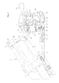
- FIG. 1 is a part of a Kipplaufgewehrs with a system or closure box 1, a tiltable at the front end of the closure box 1 about a hinge 2 arranged running unit 3 and a closure box 1 slidably guided closure block 4 shown.
- the running unit 3 includes in the embodiment shown two with their rear ends within a hook piece 5 superposed runs arranged 6 and 7 with the respective cartridge bearings 8 and 9.
- the hook piece 5 has at its back a downwardly open recess 10 for receiving the closure block. 4 on.
- an inner locking groove 11 is provided with an upper support surface 12 for the closure block 4 in the hook piece 5.
- the hook piece 5 contains two spaced-apart closure hooks 13, which have lower support surfaces 14 for the closure block 4 on the front side.
- the two locking hooks 13 also contain on the top of their rear nose-shaped protruding ends inclined upper locking surfaces 15 for a slidably disposed in the closure box 1 in the longitudinal direction and through a closure lever 16 via a closure lever shaft 17 operable closure wedge 18.
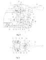
- the two closure hooks 13 with the intervening recess 10 for the closure block 4 and the two locking surfaces 15 and the closure wedge 18 are also in the FIGS. 4 and 6 shown.
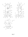
- the closure block 4 shown there in various views includes an upwardly projecting semicircular locking lug 19 with a rear-side upper locking surface 20 which engages the upper support surface 12 of the hook piece 3 when the weapon is locked.
- the closure block 4 includes a T-shaped locking lug 21 projecting forward as seen in the firing direction and including lower locking surfaces 22 for engaging the lower support surfaces 14 of the latch hook 13 on the hook piece 5 at the rear of its outwardly projecting legs.
- the closure block 4 is within a in FIG. 8 recognizable guide 24 of the lock box 1 with inwardly projecting vertical guide webs 25 between a in FIG. 3 shown lower unlocking position and a in FIG. 5 shown upper locking position perpendicular to the longitudinal direction of the closure box 1, that is, at right angles to the axes of the two barrels 6 and 7 with the running unit 3, slidably guided.
- the closure block 4 also has at its lower end a rearwardly projecting hook 26 with an oblique upper control surface 27 which, upon opening of the closure, comes into contact with an associated oblique lower footprint 28 on the underside of the closure wedge 18.
- At the bottom of the closure block includes a vertical bore 32 in which a in FIG. 1 illustrated spring-loaded bolt 33 is arranged. By the bolt 33, which is supported with its lower end on a fastened to the underside of the lock box 1 lock plate 34, the shutter block 4 is pushed upwards.
- a lateral recess 35 for a in FIG. 7 illustrated locking pin 36 is provided.
- In the closure block 4 are also holes 37 and 38 for the in FIG. 1 shown firing pin 39 and 40th
- the closure wedge 18 has two front fork-shaped protruding front ends with oblique upper abutment surfaces 41 for engagement with the in FIG. 3 recognizable inclined surfaces 30 of the closure block 4.
- At the bottom of the two fork-shaped protruding front ends of the closure wedge 18 are located in FIG. 3 recognizable oblique bottom locking surfaces 42, which at the in FIG. 5 shown locking position to rest on the associated oblique upper locking surfaces 15 to the locking hook 13.
- FIG. 5 illustrated locking position of the shutter wedge 18 abuts with its upper surface 43 on the lower locking surfaces 31 of the closure block 4, whereby it is held in the upper locking position.
- a lever 44 For displacement of the closure wedge 18 between a in FIG. 5 shown front closed position and one in FIG. 1 shown rear opening position, a lever 44 is attached to the lower end of the rotatable by the shutter lever 16 lock lever shaft 17.
- the lever 44 includes a laterally projecting lever arm 45 with an upwardly projecting pin 46 for engagement in a transverse groove 47 of the closure wedge 18.
- the shutter lever shaft 17 is rotatably disposed in the shutter box 1 perpendicular to the longitudinal direction thereof, and has two passages for two pins 48 and 49 slidably disposed in the shutter box 1 for actuating the firing pins 39 and 40, respectively.
- the pins 48 and 49 are according to FIG. 5 arranged such that they are aligned in the upper locking position of the closure block 4 with the firing pin 39 and 40 therein.
- the pins 48 and 49 are actuated by striker not shown here a trigger mechanism.
- a return mechanism for the closure wedge 18 is formed.
- the reset lever 50 is mounted in the locking lever 17 and has a lever arm 52 projecting laterally therefrom.
- the acted upon by a return spring 53 pin 51 is disposed in a bore 54 of the closure box 1 such that it presses with its free end on the lever arm 52 and thereby the closure lever shaft 17 from the in FIG. 8 shown back to its closed position.
- the shutter wedge 18 is pressed into its front closed position.
- closure block 4 In the FIGS. 5 and 6 is the locked Kipplaufgewehr with folded hook piece 5 and located in the upper locking position closure block 4 is shown.
- the closure block 4 In the upper locking position, the closure block 4 is supported with its upper locking surface 20 on the upper support surface 12 and with its two lower locking surfaces 22 on the lower support surfaces 14 of the hook piece 5.
- the closure wedge 18 is in the front closed position and lies with the two oblique lower locking surfaces 41 on the upper locking surfaces 15 of the hook piece 5.
- the corresponding bearing surfaces 55 between the closure wedge 18 and the hook piece 5 are in FIG. 6 hatched shown.
- the locking wedge 18 is in engagement with the lower locking surfaces 31 of the locking block 4 with its upper surface 42 at the forwardly projecting ends.
- FIG. 6 The corresponding bearing surfaces 56 between the locking wedge 18 and the locking block 4 are shown in FIG. 6 also hatched drawn.
- the closure block 4 forms a solid unit with the hook piece 5 and covers with its front shock bottom surface 57, the two cartridge bearings 8 and 9 from the rear.
- locking pin 36 engages in the lateral groove 35 of the closure block 4 and thereby holds the closure block 4 in the lower unlocked position.
- the front end of the locking wedge 18 is spaced from the rear ends of the locking hooks 13, so that the running unit 3 according to FIG. 1 can be tilted forward.
- the shutter block 4 is held in the lower unlocking position even when the shutter wedge 18 is pushed back by the reset lever 50 and the spring-loaded pin 51 via the shutter lever shaft 17 forward and with its oblique front bearing surfaces 41 in engagement with the rear Sloping surfaces 30 of the closure block 4 passes.
- the closure block 4 by a displacement of the closure wedge 18 in the front closed position by means of the locking lever 16 on the inclined front abutment surfaces 41 and the associated inclined surfaces 30th be moved on the closure block 4 by hand in the upper locking position. This provides additional security.
- the closure block 4 In the front closed position of the closing wedge 18 not only the hook piece 13 is locked by the closing wedge 4, but also the closing block 4 is locked in the upper locking position.
Landscapes
- Engineering & Computer Science (AREA)
- General Engineering & Computer Science (AREA)
- Operating, Guiding And Securing Of Roll- Type Closing Members (AREA)
- Aiming, Guidance, Guns With A Light Source, Armor, Camouflage, And Targets (AREA)
- Catching Or Destruction (AREA)
- Adornments (AREA)
- Packaging Of Annular Or Rod-Shaped Articles, Wearing Apparel, Cassettes, Or The Like (AREA)
Applications Claiming Priority (1)
| Application Number | Priority Date | Filing Date | Title |
|---|---|---|---|
| DE200710044993 DE102007044993B3 (de) | 2007-09-20 | 2007-09-20 | Kipplaufgewehr mit Blockverschluss |
Publications (2)
| Publication Number | Publication Date |
|---|---|
| EP2040022A2 true EP2040022A2 (fr) | 2009-03-25 |
| EP2040022A3 EP2040022A3 (fr) | 2011-03-16 |
Family
ID=40086452
Family Applications (1)
| Application Number | Title | Priority Date | Filing Date |
|---|---|---|---|
| EP08160934A Withdrawn EP2040022A3 (fr) | 2007-09-20 | 2008-07-23 | Arme à feu à bascule avec culasse à bloc |
Country Status (3)
| Country | Link |
|---|---|
| EP (1) | EP2040022A3 (fr) |
| DE (1) | DE102007044993B3 (fr) |
| RU (1) | RU2401965C2 (fr) |
Families Citing this family (9)
| Publication number | Priority date | Publication date | Assignee | Title |
|---|---|---|---|---|
| DE102009011939B4 (de) | 2009-03-10 | 2015-11-26 | Rheinmetall Waffe Munition Gmbh | Verriegelungsvorrichtung für einen Verschluss |
| ITMI20111185A1 (it) | 2011-06-29 | 2012-12-30 | Benelli Armi Spa | Chiusura per armi a bascula |
| DE102014102658B3 (de) | 2014-02-28 | 2015-04-09 | L&O Hunting Group GmbH | Kipplaufgewehr mit Blockverschluss |
| DE202014100916U1 (de) | 2014-02-28 | 2015-06-08 | L&O Hunting Group GmbH | Kipplaufgewehr mit Blockverschluss |
| DE202014100915U1 (de) | 2014-02-28 | 2015-06-08 | L&O Hunting Group GmbH | Handfeuerwaffe mit Verschlusshebel |
| DE102014102657B3 (de) | 2014-02-28 | 2015-04-30 | L&O Hunting Group GmbH | Handfeuerwaffe mit Verschlusshebel |
| RU2579367C1 (ru) * | 2015-03-11 | 2016-04-10 | Сергей Александрович Киселев | Узел запирания откидывающегося блока стволов огнестрельного оружия |
| RU2605465C1 (ru) * | 2015-10-13 | 2016-12-20 | Сергей Александрович Киселев | Узел запирания откидывающегося ствольного блока огнестрельного оружия |
| EP4563930A1 (fr) * | 2023-12-01 | 2025-06-04 | Zoli Antonio S.r.l. | Arme à feu à canon basculant avec maniement amélioré |
Citations (4)
| Publication number | Priority date | Publication date | Assignee | Title |
|---|---|---|---|---|
| DE8519C (de) | A. LEUE, Büchsenmacher, in Berlin, Thurmstrafse 59 I | Neuerungen an Hinterladern | ||
| AT288205B (de) | 1968-12-03 | 1971-02-25 | Helmut Scheiring Duesel | Blockverschluß für Kipplaufjagdwaffen |
| DE4446906C1 (de) | 1994-12-27 | 1996-06-05 | Suhler Jagd & Sportwaffen Gmbh | Kipplaufwaffe mit Blockverschluß |
| DE19909580B4 (de) | 1999-03-04 | 2007-04-12 | Suhler Jagd- Und Sportwaffen Gmbh | Kipplaufwaffe mit herausnehmbarem Blockverschluß |
Family Cites Families (3)
| Publication number | Priority date | Publication date | Assignee | Title |
|---|---|---|---|---|
| GB191414517A (en) * | 1914-06-17 | 1915-05-06 | Arthur Henry Hill | Improvements in "Under and Over" Guns. |
| DE2841938A1 (de) * | 1978-09-27 | 1980-04-10 | Horst Blaser | Blockverschluss fuer kipplaufjagdwaffen |
| DE10118046A1 (de) * | 2001-04-11 | 2002-10-24 | Blaser Horst Jagdwaffen | Schloßsystem für mehrläufige Gewehre |
-
2007
- 2007-09-20 DE DE200710044993 patent/DE102007044993B3/de not_active Expired - Fee Related
-
2008
- 2008-07-23 EP EP08160934A patent/EP2040022A3/fr not_active Withdrawn
- 2008-09-18 RU RU2008137264/02A patent/RU2401965C2/ru not_active IP Right Cessation
Patent Citations (4)
| Publication number | Priority date | Publication date | Assignee | Title |
|---|---|---|---|---|
| DE8519C (de) | A. LEUE, Büchsenmacher, in Berlin, Thurmstrafse 59 I | Neuerungen an Hinterladern | ||
| AT288205B (de) | 1968-12-03 | 1971-02-25 | Helmut Scheiring Duesel | Blockverschluß für Kipplaufjagdwaffen |
| DE4446906C1 (de) | 1994-12-27 | 1996-06-05 | Suhler Jagd & Sportwaffen Gmbh | Kipplaufwaffe mit Blockverschluß |
| DE19909580B4 (de) | 1999-03-04 | 2007-04-12 | Suhler Jagd- Und Sportwaffen Gmbh | Kipplaufwaffe mit herausnehmbarem Blockverschluß |
Also Published As
| Publication number | Publication date |
|---|---|
| RU2401965C2 (ru) | 2010-10-20 |
| RU2008137264A (ru) | 2010-03-27 |
| EP2040022A3 (fr) | 2011-03-16 |
| DE102007044993B3 (de) | 2009-01-08 |
Similar Documents
| Publication | Publication Date | Title |
|---|---|---|
| DE102007044993B3 (de) | Kipplaufgewehr mit Blockverschluss | |
| EP1830152B1 (fr) | Chargeur enfichable pour arme à feu | |
| DE1553916C3 (de) | Gewehr mit Fallblockverschluß | |
| DE2752721C2 (de) | Verschlußblockanordnung für eine automatische Schußwaffe | |
| EP1387141B1 (fr) | Arme à feu à bascule | |
| EP4038333B1 (fr) | Carabine dotée d'une poignée de charge | |
| DE60122760T2 (de) | Eine schiebedachkonstruktion für ein fahrzeug sowie ein mit einer solchen schiebedachkonstruktion versehenes fahrzeug | |
| EP2469216A2 (fr) | Dispositif de sécurité pour fusils à répétition | |
| DE2240878C3 (de) | Revolver | |
| EP4273493B1 (fr) | Arme de poing avec verrouillage de culasse | |
| DE3109730A1 (de) | Selbstladepistole | |
| DE202007013219U1 (de) | Kipplaufgewehr mit Blockverschluss | |
| AT413603B (de) | Pistole mit halbstarrer verriegelung | |
| DE102009058551A1 (de) | Weiterentwickeltes, rückstoßbetriebenes, selbsttätig in Schußrichtung öffnendes Verschlußsystem für Feuerwaffen | |
| DE3613680C2 (fr) | ||
| AT409548B (de) | Repetierbüchse | |
| AT517073B1 (de) | Repetierbüchse | |
| AT526230B1 (de) | Feuerwaffe vom Bullpup-Typ | |
| EP0862038A2 (fr) | Fusil à bascule avec culasse à bloc | |
| DE202019103153U1 (de) | Verschlussvorrichtung für eine schwenkbare Bordwand eines Kipper-Fahrzeugs | |
| DE202006003351U1 (de) | Steckmagazin einer Handfeuerwaffe | |
| DE10118045B4 (de) | Sicherungsvorrichtung für eine Kipplaufwaffe | |
| DE94733C (fr) | ||
| EP3885692A1 (fr) | Fermeture de canon d'arme et arme à canon | |
| EP2913621B1 (fr) | Fusil à bascule doté d'une culasse à bloc |
Legal Events
| Date | Code | Title | Description |
|---|---|---|---|
| PUAI | Public reference made under article 153(3) epc to a published international application that has entered the european phase |
Free format text: ORIGINAL CODE: 0009012 |
|
| AK | Designated contracting states |
Kind code of ref document: A2 Designated state(s): AT BE BG CH CY CZ DE DK EE ES FI FR GB GR HR HU IE IS IT LI LT LU LV MC MT NL NO PL PT RO SE SI SK TR |
|
| AX | Request for extension of the european patent |
Extension state: AL BA MK RS |
|
| PUAL | Search report despatched |
Free format text: ORIGINAL CODE: 0009013 |
|
| AK | Designated contracting states |
Kind code of ref document: A3 Designated state(s): AT BE BG CH CY CZ DE DK EE ES FI FR GB GR HR HU IE IS IT LI LT LU LV MC MT NL NO PL PT RO SE SI SK TR |
|
| AX | Request for extension of the european patent |
Extension state: AL BA MK RS |
|
| 17P | Request for examination filed |
Effective date: 20110916 |
|
| AKX | Designation fees paid |
Designated state(s): AT BE BG CH CY CZ DE DK EE ES FI FR GB GR HR HU IE IS IT LI LT LU LV MC MT NL NO PL PT RO SE SI SK TR |
|
| RIC1 | Information provided on ipc code assigned before grant |
Ipc: F41A 3/58 20060101AFI20120801BHEP Ipc: F41C 7/11 20060101ALN20120801BHEP |
|
| GRAP | Despatch of communication of intention to grant a patent |
Free format text: ORIGINAL CODE: EPIDOSNIGR1 |
|
| STAA | Information on the status of an ep patent application or granted ep patent |
Free format text: STATUS: THE APPLICATION IS DEEMED TO BE WITHDRAWN |
|
| 18D | Application deemed to be withdrawn |
Effective date: 20130206 |