EP2040071A2 - Gassorptionsmessgerät zur schnellen Untersuchung mehrerer Proben - Google Patents
Gassorptionsmessgerät zur schnellen Untersuchung mehrerer Proben Download PDFInfo
- Publication number
- EP2040071A2 EP2040071A2 EP08164140A EP08164140A EP2040071A2 EP 2040071 A2 EP2040071 A2 EP 2040071A2 EP 08164140 A EP08164140 A EP 08164140A EP 08164140 A EP08164140 A EP 08164140A EP 2040071 A2 EP2040071 A2 EP 2040071A2
- Authority
- EP
- European Patent Office
- Prior art keywords
- gas
- sample
- hydride
- sensor
- sensors
- Prior art date
- Legal status (The legal status is an assumption and is not a legal conclusion. Google has not performed a legal analysis and makes no representation as to the accuracy of the status listed.)
- Withdrawn
Links
Images



Classifications
-
- G—PHYSICS
- G01—MEASURING; TESTING
- G01N—INVESTIGATING OR ANALYSING MATERIALS BY DETERMINING THEIR CHEMICAL OR PHYSICAL PROPERTIES
- G01N33/00—Investigating or analysing materials by specific methods not covered by groups G01N1/00 - G01N31/00
- G01N33/0004—Gaseous mixtures, e.g. polluted air
- G01N33/0009—General constructional details of gas analysers, e.g. portable test equipment
- G01N33/0027—General constructional details of gas analysers, e.g. portable test equipment concerning the detector
- G01N33/0031—General constructional details of gas analysers, e.g. portable test equipment concerning the detector comprising two or more sensors, e.g. a sensor array
-
- G—PHYSICS
- G01—MEASURING; TESTING
- G01N—INVESTIGATING OR ANALYSING MATERIALS BY DETERMINING THEIR CHEMICAL OR PHYSICAL PROPERTIES
- G01N21/00—Investigating or analysing materials by the use of optical means, i.e. using sub-millimetre waves, infrared, visible or ultraviolet light
- G01N21/75—Systems in which material is subjected to a chemical reaction, the progress or the result of the reaction being investigated
- G01N21/77—Systems in which material is subjected to a chemical reaction, the progress or the result of the reaction being investigated by observing the effect on a chemical indicator
- G01N21/78—Systems in which material is subjected to a chemical reaction, the progress or the result of the reaction being investigated by observing the effect on a chemical indicator producing a change of colour
- G01N21/783—Systems in which material is subjected to a chemical reaction, the progress or the result of the reaction being investigated by observing the effect on a chemical indicator producing a change of colour for analysing gases
-
- G—PHYSICS
- G01—MEASURING; TESTING
- G01N—INVESTIGATING OR ANALYSING MATERIALS BY DETERMINING THEIR CHEMICAL OR PHYSICAL PROPERTIES
- G01N33/00—Investigating or analysing materials by specific methods not covered by groups G01N1/00 - G01N31/00
- G01N33/0004—Gaseous mixtures, e.g. polluted air
- G01N33/0009—General constructional details of gas analysers, e.g. portable test equipment
- G01N33/0022—General constructional details of gas analysers, e.g. portable test equipment using a number of analysing channels
- G01N33/0024—General constructional details of gas analysers, e.g. portable test equipment using a number of analysing channels a chemical reaction taking place or a gas being eliminated in one or more channels
-
- G—PHYSICS
- G01—MEASURING; TESTING
- G01N—INVESTIGATING OR ANALYSING MATERIALS BY DETERMINING THEIR CHEMICAL OR PHYSICAL PROPERTIES
- G01N33/00—Investigating or analysing materials by specific methods not covered by groups G01N1/00 - G01N31/00
- G01N33/0004—Gaseous mixtures, e.g. polluted air
- G01N33/0009—General constructional details of gas analysers, e.g. portable test equipment
- G01N33/0027—General constructional details of gas analysers, e.g. portable test equipment concerning the detector
- G01N33/0036—General constructional details of gas analysers, e.g. portable test equipment concerning the detector specially adapted to detect a particular component
- G01N33/005—H2
-
- G—PHYSICS
- G01—MEASURING; TESTING
- G01N—INVESTIGATING OR ANALYSING MATERIALS BY DETERMINING THEIR CHEMICAL OR PHYSICAL PROPERTIES
- G01N7/00—Analysing materials by measuring the pressure or volume of a gas or vapour
- G01N7/02—Analysing materials by measuring the pressure or volume of a gas or vapour by absorption, adsorption, or combustion of components and measurement of the change in pressure or volume of the remainder
Definitions
- Embodiments of the present invention relate generally to devices for performing measurements on small quantities of gases or liquids, and particularly to an apparatus for performing gas sorption measurements on multiple samples of gas-sorbing materials.
- Synthesis of materials using combinatorial chemistry has been used effectively to produce new materials having small variations in composition and/or structure numbering in the 10s, 100s or 1000s at a time.
- Such materials processing methods have led to the discovery of new and improved chemicals, pharmaceuticals, semiconductor materials and devices.
- combinatorial methods can only lead to timely material discovery when rapid screening of the physical characteristics of the many types of new materials produced thereby is available.
- the gas sorption properties of each new material must be tested, i.e., the absorption, adsorption, desorption, physisorption, and/or chemisorption properties, and such testing for even a single sample is a lengthy and labor-intensive process.
- Such tests include establishing pressure-composition-temperature (PCT) curves for materials, and performing isothermal kinetics and capacity measurements, thermodynamic measurements (van't Hoff curves) and temperature-programmed desorption (TPD) measurements.
- One embodiment of the present invention sets forth an apparatus that can determine the gas sorption properties of a large number of material samples simultaneously.
- the apparatus includes a switchable manifold configured to fluidly couple an array of sensors and an array of samples to a vacuum source, a dosing gas source, and each other.
- the array of sensors may include pressure transducers, conventional gas detectors, resistivity sensors, and hydrogen-induced phase-change materials including hydride-based sensors.
- One advantage of the disclosed apparatus is that can be used to efficiently determine gas sorption properties of a large number of material samples simultaneously and with high accuracy.
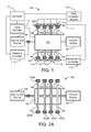
- Figure 1 is a schematic diagram of a gas sorption apparatus configured to perform tests on multiple samples simultaneously, according to an embodiment of the invention.
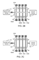
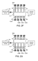
- FIGS 2A-G schematically illustrate different operations performed by a gas sorption apparatus in the course of sorption testing, according to embodiments of the invention.
- Figure 3 is a schematic illustration of a sample library, according to an embodiment of the invention.
- Figures 4A , B illustrate schematic side views of one embodiment of the isolation of each sample area of a sample library from adjacent sample areas.
- Figure 5 is a schematic side view of a sensor array containing an electrically responsive material, according to an embodiment of the invention.
- Figure 6 is a schematic side view of a sensor array containing an optically responsive material, according to an embodiment of the invention.
- Figure 7 is a schematic side view of another embodiment of a sensor that includes an optically responsive material and may be contained in a sensor array.
- Figure 8 illustrates a schematic top view of a sensor array containing a plurality of sensors after sorption testing.
- Embodiments of the invention contemplate an apparatus that determines gas sorption properties of a large number of material samples simultaneously.
- the apparatus includes a switchable manifold of low-volume conduits and an array of sensors, where each low-volume conduit fluidly couples a single sample of gas-sorbing material to a dedicated detector.
- the switchable manifold is also configured to fluidly couple the samples and/or sensors to a vacuum source and a dosing gas source. Because of the very low internal volume of the conduits, essentially all gas released from a particular sample is accurately detected by the corresponding detector, either through sorption of the released gas, by measuring pressure, or by other means. In this way, a very accurate measurement of the quantity of gas released by the sample is made.
- the array of sensors includes hydride-based sensors, which contain a material that forms an optically and/or electrically responsive hydride upon exposure to hydrogen-containing gas.
- FIG. 1 is a schematic diagram of a gas sorption apparatus 100 configured to perform tests on multiple samples simultaneously, according to an embodiment of the invention.
- the principle components of gas sorption apparatus 100 include a switchable manifold 101, an array 102 of sensors 102A-D, a plurality of samples 103A-D, a dosing gas source 104 and a vacuum source 105.
- gas sorption apparatus 100 may also include a controller 110 coupled to a valve controller 111, a pressure controller 112, a temperature controller 113, a heater assembly 115, and a data collection system 114.
- Controller 110 is an electronic controller, such as a microprocessor, and is configured to control the operation of gas sorption apparatus 100, e.g., valve operation, pressure control, vacuum control, electronic data collection, temperature control and/or dosing quantity and frequency.
- Switchable manifold 101 is configured to fluidly couple samples 103A-D to detectors 102A-D by means of a low volume path.
- switchable manifold 101 includes low-volume conduits 106.
- the internal volume of low-volume conduits 106 is advantageously minimized.
- low-volume conduits 106 comprise small-diameter electro-polished stainless steel tubing, having an internal diameter of 2 mm or less.
- low-volume conduits 106 may be small-diameter holes formed through the body of switchable manifold 101, e.g., by laser drilling, chemical growth, chemical etching, or other techniques.
- low-volume conduits 106 may have outer diameters as small as 1 micron.
- the total free volume between a given sample and corresponding sensor may be 0.1 ml or less.
- low-volume conduits 106 preferably is characterized by low gas-permeability and out-gassing, such as stainless steel, glass, ceramic materials, alumina, MacorTM, and other ultra-high vacuum (UHV) compatible materials.
- low-volume conduits 106 may be configured to thermally isolate sensors 102A-D from samples 103A-D, so that each sensor may be maintained at a substantially different temperature than its corresponding sample.
- low-volume conduits 106 may be formed from small-diameter tubing that conduct very little heat.
- low-volume conduits may be drilled or formed through a solid block of thermally insulative material, e.g., alumina. In this way, the samples and sensors are thermally decoupled, allowing greater flexibility in the type of sorption tests performed by gas sorption apparatus 100.
- Switchable manifold 101 also includes one or more very low-displacement valves, such as such as rotating valves and/or sliding valves, for fluidly coupling and decoupling sensors 102A-D from samples 103A-D, respectively as well as for fluidly coupling sensors 102A-D from samples 103A-D from dosing gas source 104 or vacuum source 105.
- Very low-displacement valves are known in the art, and are well suited for applications in which conduits formed through a solid material need to be sealed.
- a very low-displacement valve or valves may be incorporated into the body of the Switchable manifold 101 as a system of rotating or sliding plates with fluid coupling holes and grooves between sealing gaskets.
- use of very low-displacement valves may substantially reduce error in pressure- and volume-dependent measurements, such as PCT measurements.
- An example of the mechanical organization and operation of a sliding valve 406 is described below in conjunction with Figure 4A .
- Array 102 includes a plurality of sensors 102A-D, each of which is fluidly coupled to a single low-volume conduit 106. Sensors 102A-D may be individually positioned in fluid contact with low-volume conduits 106, as shown in Figure 1 . Alternatively, sensors 102A-D may be configured as a single assembly or sensor array, as described below in conjunction with Figures 5-7 . It is contemplated that sensors 102A-D may be selected from a wide variety of possible sensor types, depending on the particular dosing gas used and specific test being performed. Sensors that may be used in array 102 include pressure transducers and conventional gas detectors.
- array 102 may include hydride-based sensors, which contain a material that forms an optically and/or electrically responsive hydride upon exposure to hydrogen-containing gas.
- gas sorption apparatus 100 is illustrated in Figure 1 with only four sensors 102A-D, and array 102 is depicted as a linear array.
- embodiments of the invention contemplate array 102 containing a large number of sensors, e.g., 10s or 100s of sensors.
- the sensors making up array 102 may be arranged in a two-dimensional array, as illustrated below in Figure 8 , the two-dimensional array having a means to fluidly separate each detector one-from-another.
- the sensors or sensor arrays may be replaceable to allow sensor types to be changed depending on the experimental conditions, or easily replaced when contaminated or not functioning.
- sensors A-D of array 102 may be pressure transducers, which are high-accuracy pressure measuring device capable of detecting changes in relative or absolute pressure in each of low-volume conduits 106 to the degree necessary for performing gas sorption tests.
- types of pressure transducers suitable for use in array 102 include a strain-gauge pressure transducer, a piezoelectric pressure transducer, or a capacitance manometer, such as a Model 870B Micro-Baratron® or chip-based micro-pressure-sensors.
- each sensor in array 102 may include an array of multiple pressure transducers, each having a different operating pressure range.
- gas sorption apparatus 100 may be used as a Sievert's device to perform a PCT measurement or a TPD measurement of specific gases as they are absorbed or desorbed from each of samples 103A-D.
- each of sensors 102A-D may also include a temperature sensor. In this way, the temperature and pressure of the dosing gas being tested are both known.
- sensors 102A-D are fluidly coupled to samples 103A-D, respectively, via low-volume conduits 106.
- the internal volume of low-volume conduits 106 is a small and accurately known volume, the pressure changes that occur in the volume between sensors 102A-D and samples 103 due to sorption or desorption of a dosing gas are compounded. Therefore, the mass of dosing gas that flows into or out of each material sample can be very accurately determined.
- Array 102 may include conventional gas sensors known in the art, such as flammable gas detectors or other gas sensors.
- sensors 102A-D may be used to quantify the amount of dosing gas released from or absorbed by samples 103A-D based on a property change of a reactive material contained in the sensor, such as resistivity change. Because the resistivity of the reactive material may be function of how much dosing gas is present, the quantity of desorbed dosing gas is easily measured.
- array 102 may include fuel cell-based sensors, which are designed to produce a voltage upon reaction with a dosing gas, particularly hydrogen-containing gases.
- array 102 may include thermal conductivity or gas resistivity sensors that measure the density of gas within the low-volume conduits 106.
- array 102 may include hydride-based sensors, which contain a material that forms an optically and/or electrically responsive hydride upon exposure to hydrogen-containing gas.
- Hydride-forming materials as defined herein, include any material that changes physical properties on contact with hydrogen, and is not meant to necessarily imply the formation of a stoichiometric hydride compound. Hydride-forming materials that may be used in hydride-based sensors include yttrium (Y), lanthanum (La), magnesium-titanium (Mg-Ti) alloys, magnesium-nickel (Mg-Ni) alloys, and various palladium (Pa) alloys.
- Yttrium is one example of an optically responsive material that may be used in a hydride-based sensor, according to an embodiment of the invention.
- Yttrium is highly reflective at visible wavelengths, and forms hydrides (YH 2 and YH 3 ) that each have different reflectivities.
- YH 2 is slightly less reflective than yttrium, and YH 3 is nearly transparent. Therefore, when hydrogen gas is brought in contact with yttrium, an optical detector will register less light reflected from the surface of the yttrium as more hydrogen is absorbed by the yttrium.
- a correlation between the quantity of hydrogen gas absorbed and the intensity of light registered by the optical detector can be constructed, so that the reflectance of the sensor indicates the quantity of gas that has been absorbed by the detector and, therefore, released by the sample.
- Such processes are most advantageous when the detector material is reversible under typical operating conditions, however it is contemplated that one-time-use only detectors may be used.
- Some materials, such as yttrium may require an active, gas-transparent coating, such as a palladium cap to prevent oxidation of the yttrium and possibly also act as a catalyst for dissociation of the active gas such as hydrogen.
- Each of samples 103A-D includes a material sample prepared for sorption testing. Hence, each material sample is isolated from the ambient environment in an gas-tight fashion and held in a small-volume chamber.
- Each material sample may be a thin-film material deposited on a substrate, a bulk sample, or any other morphology conducive to sorption testing, such as a bulk sample that has been pulverized.
- a filter may be disposed between each sample and the low-volume conduit 106 fluidly coupled thereto, to prevent contamination and fouling of the low-volume conduit 106 by the sample material.
- each of samples 103A-D may be individually positioned in fluid contact with low-volume conduits 106, as shown in Figure 1 .
- samples 103A-D may be configured as a single assembly, such as a sample library. Sample libraries, according to embodiments of the invention, are described below in conjunction with Figure 3 .
- Valve controller 111 operates pressure controller 112 and the very low-displacement valves contained in switchable manifold 101, thereby establishing the connections between dosing gas source 104, vacuum source 105, samples 103A-D, and sensors 102A-D.
- Pressure controller 112 controls the pressure of gas introduced into switchable manifold 101 from dosing gas source 104, which is beneficial for certain sorption measurements.
- the control valve may consist of a manual or software-controlled pressure regulator, a flow control device, or needle valve.
- Temperature controller 113 controls the individual heaters 116 that make up heater assembly 115, to maintain each of samples 103A-D and sensors 102A-D at a prescribed temperature or temperature history, such as a controlled temperature ramping rate.
- an individual heater 116 may be positioned in proximity to each of samples 103A-D and/or sensors 102A-D. Controlling the sample and detector temperature aids in performing certain sorption measurements.
- Data collection system 114 is configured to obtain information from each of sensors 102A-D. The information may be obtained, for example, by an electrical connection, an optical connection, or though an optical system that images the sensors.
- gas sorption apparatus 100 is configured to perform one or more sorption tests simultaneously on a plurality of samples. Depending on the type of sensors in array 102, gas sorption apparatus 100 may perform PCT and TPD tests on samples 103A-D and generate kinetic and thermodynamic stability information about the samples. In the course of such testing, switchable manifold 101 fluidly couples samples 103A-D and/or sensors 102A-D, to dosing gas source 104, and to vacuum source 105, as well as to each other.
- Figures 2A-G schematically illustrate various operations performed by gas sorption apparatus 100 in the course of such sorption testing, according to different embodiments of the invention.
- Figure 2A schematically illustrates gas sorption apparatus 100 with switchable manifold 101 positioned to fluidly couple samples 103A-D and sensors 102A-D to vacuum source 105 for evacuation of any gases contained therein. Evacuation may be performed as part of a preparation process for testing of samples 103A-D.
- Figure 2B schematically illustrates gas sorption apparatus 100 with switchable manifold 101 disposed to fluidly couple samples 103A-D to dosing gas source 104 for fully charging samples 103A-D and sensors 102A-D in preparation for desorption PCT dosing measurements.
- FIG. 2C schematically illustrates gas sorption apparatus 100 with switchable manifold 101 positioned to fluidly couple each of samples 103A-D to a corresponding sensor 102A, 102B, 102C, or 102D.
- each of sensors 102A-D are in direct "gas contact" to a corresponding sample by means of a fluid path that has very little, if any, free volume, i.e., a low-volume conduit 106.
- Figure 2D schematically illustrates gas sorption apparatus 100 with switchable manifold 101 positioned to fluidly couple each of sensors 102A-D to vacuum source 105, to pump-down sensors 102A-D.
- Figure 2E schematically illustrates gas sorption apparatus 100 with switchable manifold 101 positioned to fluidly couple each of samples 103A-D to vacuum source 105, to pump-down samples 103A-D.
- Figure 2F schematically illustrates gas sorption apparatus 100 with switchable manifold 101 positioned to fluidly couple each of sensors 102A-D to dosing gas source 104, to charge sensors 102A-D with a dosing gas.
- Figure 2G schematically illustrates gas sorption apparatus 100 with switchable manifold 101 positioned to fluidly couple each of samples 103A-D to dosing gas source 104, to charge samples 103A-D with a dosing gas.
- an absorption PCT measurement procedure is described with respect to the different configurations of gas sorption apparatus 100 illustrated in Figures 2A-G .
- sensors 102A-D and samples 103A-D are evacuated, as shown in Figure 2A .
- samples 103A-D are isolated and dosing gas is introduced to sensors 102A-D, as illustrated in Figure 2F .
- Sensors 102A-D are then fluidly coupled to samples 103A-D as illustrated in Figure 2C , and the change in gas concentration in each of sensors 102A-D and corresponding low-volume conduits 106 is measured as each of samples 103A-D absorb the dosing gas.
- the quantity of gas change in each of sensors 102A-D and low-volume conduits 106 is used to calculate the quantity of gas absorbed by each of samples 103A-D, and a point on the PCT curve for each sample is plotted. This procedure is then repeated at increasingly higher pressures to generate additional points and thereby construct a full PCT curve for each of samples 103A-D.
- Desorption PCT curves may be performed in the same manner, except that one would start by fully charging the sample and detectors at the highest pressure by exposing both samples 103A-D and sensors 102A-D to the gas source at highest pressure and then dosing gas out of each sample by decreasing the pressure in the sensor and conduit in steps as above.
- each of sensors 102A-D may be pressure sensors rather than concentration sensors to construct true equilibrium PCT curves, since the final equilibrium pressure should be known at each dose and because concentration can be determined in the classic Sieverts method by knowing the volume, gas temperature and pressure change. Due to the difficulty in making an array of highly accurate, separate pressure sensors, it is contemplated that, in one embodiment, gas sorption apparatus 100 may perform such measurements in an easier but less accurate way.
- a concentration sensor such as the metal-hydride optical sensors described below in conjunction with Figures 6 and 7 , measures only the concentration change with each dose. This concentration change may be plotted versus the applied dosing pressure, which may be taken from a single pressure sensor at the dosing gas supply line.
- Kinetics and TPD measurements can also be performed by gas sorption apparatus 100, by configuring gas sorption apparatus 100 as illustrated in Figures 2A-G . Since such measurements are concentration vs. time and concentration vs. temperature, it is not necessary to have individual pressure sensors for each sample for these measurements.
- samples 103A-D are arranged in a sample library, which is positioned in fluid contact with low-volume conduits 106 prior to sorption testing.
- Figure 3 is a schematic illustration of a sample library 300, according to an embodiment of the invention.
- Sample library includes a plurality of sample areas s, each surrounded by a border b.
- Sample areas s are discretized regions on the surface of a substrate, such as a glass substrate, metal substrate, or silicon wafer. Each of sample areas s may include a different material composition.
- the plurality of material compositions contained in sample library 300 may be formed thereon by any known combinatorial techniques or other technically feasible approaches including discrete or continuous deposition techniques.
- a continuous spectrum of material compositions of continuously varying mixtures may be formed over the substrate of sample library 300 using co-deposition of different materials on the substrate.
- the sample areas s then discretize the continuously varying mixtures on the substrate, dividing the substrate into small areas of approximately constant composition. In this way, a large number of samples of different compositions can be quickly prepared and simultaneously measured using gas sorption apparatus 100.
- one or more sample areas s in sample library 300 contain material compositions of known sorption properties, to be used for reference or calibration purposes.
- each sample area s may be relatively small, so that a large number of different material compositions, e.g., 10s or 100s, can be contained in a single sample library and tested simultaneously by gas sorption apparatus 100.
- the minimum area of each sample area s is only limited by the practical limitations of the minimum width of border b and the accuracy desired for a given sorption test. Since smaller sample areas s are capable of absorbing and desorbing less total gas, the accuracy of any sorption test can be adversely affected as the area of each sample area s is reduced and as the thickness of each sample area s is reduced.
- border b is selected to form a gas or liquid barrier between the samples, so that each sample area s may be completely isolated from adjacent sample areas during sorption testing.
- border b is simply a region of sample library 300 in which no sample material has been deposited.
- border b includes an isolation member.
- the isolation member may be a raised sealing material used to establish a gas-tight seal with low-volume conduits 106.
- the surface of switchable manifold 101 may be a smooth, polished surface against which the isolation member is pressed, thereby isolating each sample area s from adjacent sample areas while fluidly coupling each sample area s to a corresponding low-volume conduit 106.
- the isolation member may be formed from a material that is subject to essentially no outgassing or gas permeability over the wide range of temperatures and pressures associated with sorption tests. Many UHV-compatible materials may be used for this purpose and are well-known, such as a O-rings or UHV high-temperature epoxy.
- the isolation member may be a grid deposited in border s, the grid being formed from a relatively soft metal, such as nickel or copper.
- the isolation member is incorporated into a surface of switchable manifold 101, as described below in conjunction with Figures 4A , B.
- FIGs 4A , B illustrate schematic side views of one embodiment of the isolation of each sample area s of sample library 300 from adjacent sample areas.
- sample library 300 is positioned proximate to a sample receiver 402 in preparation for mounting thereon.
- sample library 300 is shown mounted on sample receiver 402 and ready for sorption testing by gas sorption apparatus 100.
- each sample area s is fluidly coupled to a dedicated low-volume conduit 106, and is fluidly isolated from adjacent sample areas s when sample library 300 is mounted on sample receiver 402.
- Sample receiver 402 is configured with an array of knife edges 401 that are aligned with isolation members 405, which are disposed on sample library 300.
- isolation members 405 may be formed from a relatively soft material, such as copper, nickel, or a UHV-compatible polymer, and knife edges 401 may be a relatively hard material, such as stainless steel.
- knife edges 401 engage with isolation members 405 to fluidly isolate each of sample areas s.
- sample receiver 402 may not be configured with knife edges 401 and instead engages isolation members 405 with a substantially flat, polished surface to form the gas-tight seal.
- the surface of switchable manifold 101 may consist of an array of isolating rings, or squares of knife-edge raised material that press into isolation members 405, thereby isolating each sample area s from adjacent sample areas while fluidly coupling each sample area s to a corresponding low-volume conduit 106.
- the entire substrate of the sample library 300 is composed of material softer than the knife-edge material 401, such that the knife-edge material is pressed into the substrate between the discretized sample areas s or through a non-discretized continuous sample s, thereby isolating each sample area s from adjacent sample areas while fluidly coupling each sample area s to a corresponding low-volume conduit 106.
- Sample receiver 402 also includes low-volume conduits 106 positioned between knife edges 401, and is fluidly coupled and decoupled from switchable manifold 101 by a sliding valve 406. Sliding valve 406 actuates to fluidly couple and decouple sample receiver 402 and any sample library mounted thereon by translating horizontally as indicated by arrow 407.
- array 102 in Figure 1 includes sensors with an electrically responsive material to quantify the quantity of gas released from sample materials during sorption testing.
- sensors may include hydride-based sensors or more conventional gas detectors.
- exposure to and reaction with the dosing gas causes the electrically responsive material contained in the sensor to undergo a change in one or more electrical properties, such as resistivity or electrochemical potential.
- This change in electrical properties can then be used to quantify either the amount of dosing gas that has reacted with the electrically responsive material, or the concentration of dosing gas that is in fluid contact with the electrically responsive material.
- the quantity of gas released by a sample can be easily calculated.
- FIG. 5 is a schematic side view of a sensor array 500 containing an electrically responsive material 501, according to an embodiment of the invention.
- Sensor array 500 is one embodiment of array 102, and includes a plurality of sensors d, which are each fluidly coupled to a corresponding sample (not shown) via low-volume conduits 106 and a sliding valve 406.
- Each sensor d has a conductor that provides a signal back to data collection system 114.
- array 102 in Figure 1 includes sensors with an optically responsive material to quantify the quantity of gas released from samples material during sorption testing.
- sensors may include hydride-based sensors, where exposure to and reaction with hydrogen gas causes the optically responsive material contained in the sensor to undergo a change in one or more optical properties, such as reflectivity and/or transmissivity of visible light.
- FIG 6 is a schematic side view of a sensor array 600 containing an optically responsive material 601, according to an embodiment of the invention.
- Sensor array 600 is one embodiment of array 102, and includes a plurality of sensors 602, which are each fluidly coupled to a corresponding sample (not shown) via low-volume conduits 106 and a sliding valve 406.
- illumination 605 from a light source is directed on sensors 602, and light 606 reflected from sensors 602 is collected by an optical detector 608.
- Optical detector 608 may be a digital camera that captures the condition of multiple sensors 602 with one or more images. The images are then stored in and/or processed by data collection system 114 in Figure 1 .
- optical detector 608 may include a plurality of light sensors, such as photocells, so that each sensor 602 has a corresponding and dedicated light sensor. Thus, the optical response from each sensor may be gathered either simultaneously or individually. As noted above, exposure to the dosing gas produces a change in the reflectivity and/or transmissivity of the optically responsive material, which is measured by optical detector 608 or detectors as described herein.
- Figure 7 is a schematic side view of a sensor that includes an optically responsive material 701 and may be included in array 102, according to an alternative embodiment of the invention. Similar to sensors 602, exposure of dosing gas to sensor 700 produces an optical response in optically responsive material 701 that can be detected and/or recorded by an optical detector. In sensor 700, however, optically responsive material 701 undergoes a distinct color, transparency and/or reflectivity change upon absorption of the dosing gas, rather than a gradual change in reflectivity or transmissivity as more dosing gas is absorbed. In this fashion, a clearly defined region of optically responsive material 701 changes color when sensor 700 is exposed to a dosing gas of the appropriate chemistry.
- optically responsive material 701 may be a yttrium- or lanthanum-based compound. As is known in the art, such compounds can produce the distinct reflectivity change necessary for sensor 700 to function as contemplated herein.
- sensor 700 To isolate optically responsive material 701 from ambient hydrogen and other contamination that may result in unwanted optical changes or passivation, sensor 700 includes a protective layer 705 that isolates optically responsive material 701. Layer 705 may be the native yttrium-oxide or a secondary deposited metal oxide or impermeable metal or polymer layer, which is known to prevent diffusion of hydrogen therethrough. Sensor 700 also includes a palladium orifice or window 702 deposited in and sealing opening 707 of protective layer 705, as shown. Thus, palladium orifice 702 prevents fluid contact between gases present in low-volume conduit 106 and optically responsive material 701 preventing oxidation or passivation of the responsive material 701 in sealing opening 707.
- optically responsive material 701 should only be exposed to hydrogen that is introduced via low-volume conduit 106 and the palladium orifice 702.
- Sensor 700 responds to exposure to hydrogen by forming a circular reacted region of different color, transparency, or reflectivity centered over opening 707, where the diameter of the reacted region can be readily correlated to a quantity of hydrogen gas absorbed by sensor 700.
- the diameter of the reacted region in sensor 700 and the diameters of the reacted regions in all other sensors in the same sample library can then be recorded simultaneously by an optical detector, such as a digital camera. In this fashion, hydrogen released by a plurality of samples in sample library 300 can be simultaneously quantified, greatly speeding the screening process.
- Figure 8 illustrates a schematic top view of a sensor array 800 containing a plurality of sensors 700 after sorption testing. As shown, circular regions 801 are visible and the diameters thereof are easily measured. Thus, desorbed gas concentrations of each sample may be correlated to gas over-pressure and temperature of each sample in a single or series of measurements.
- the sensor array 800 may be pre-charged with gas to the fully absorbed state and then exposed to the sample array with each sensor acting as a gas source.
- concentration of gas absorbed by each sample can be measured quantitatively by the diameter of the desorbed circular regions 801 of the sensor array 800. Additionally, measured increases (sample desorption) or decreases (sample absorption) of the diameter of the circular regions 801 with time may provide a measurement of the individual kinetics of gas desorption or sorption of the array of samples at a given temperature or with a controlled temperature ramping.
- a sensor array containing sensors d in Figure 5 , sensors 602 in Figure 6 , and/or sensor 700 in Figure 7 may be formed on a silicon substrate or an optically transparent substrate such as glass.
- Deposition and etching processing techniques are well suited to efficiently fabricating a large number of very small sensors on a single substrate, thereby facilitating the screening of large numbers of different material compositions.
- Sensors containing either electrically and/or optically responsive material, can be formed in this manner.
- a sensor array such as sensor array 102
- hydride-based sensors may be used as mini-reservoirs of hydrogen gas and can therefore be used as "mini-dosers."
- sensor array 800 can be dosed with hydrogen such that each sensor 700 contains a known quantity of hydrogen gas.
- Sample materials in a sample library can then be fluidly coupled to vacuum source 105 of Figure 1 and/or heated, as necessary, to release the hydrogen or contaminants contained in each sample material.
- Sensors 700 are fluidly coupled to the sample library and heated, as required, to release hydrogen therefrom. Sorption of hydrogen into each sample can then be readily quantified by comparing the quantity of hydrogen actually released by each sensor 700.
- one or more of the samples so tested may be a control sample, comprising a material that is known to absorb no hydrogen.
- control samples may be used to assist in the calibration of sorption tests by quantifying how much hydrogen is present in a low-volume conduit 106 at a specific pressure and temperature and at any time during the sorption test.
Landscapes
- Chemical & Material Sciences (AREA)
- Health & Medical Sciences (AREA)
- Engineering & Computer Science (AREA)
- Life Sciences & Earth Sciences (AREA)
- Physics & Mathematics (AREA)
- Pathology (AREA)
- Analytical Chemistry (AREA)
- Biochemistry (AREA)
- General Health & Medical Sciences (AREA)
- General Physics & Mathematics (AREA)
- Immunology (AREA)
- Combustion & Propulsion (AREA)
- Food Science & Technology (AREA)
- Medicinal Chemistry (AREA)
- Chemical Kinetics & Catalysis (AREA)
- Plasma & Fusion (AREA)
- Investigating Or Analysing Materials By Optical Means (AREA)
Applications Claiming Priority (3)
| Application Number | Priority Date | Filing Date | Title |
|---|---|---|---|
| US97324807P | 2007-09-18 | 2007-09-18 | |
| US12/200,839 US20090074612A1 (en) | 2007-09-18 | 2008-08-28 | Gas Sorption Tester For Rapid Screening of Multiple Samples |
| US12/200,835 US8020426B2 (en) | 2007-09-18 | 2008-08-28 | Gas sorption tester for rapid screening of multiple samples |
Publications (2)
| Publication Number | Publication Date |
|---|---|
| EP2040071A2 true EP2040071A2 (de) | 2009-03-25 |
| EP2040071A3 EP2040071A3 (de) | 2014-01-01 |
Family
ID=40091816
Family Applications (1)
| Application Number | Title | Priority Date | Filing Date |
|---|---|---|---|
| EP08164140.9A Withdrawn EP2040071A3 (de) | 2007-09-18 | 2008-09-11 | Gassorptionsmessgerät zur schnellen Untersuchung mehrerer Proben |
Country Status (1)
| Country | Link |
|---|---|
| EP (1) | EP2040071A3 (de) |
Cited By (5)
| Publication number | Priority date | Publication date | Assignee | Title |
|---|---|---|---|---|
| CN103558341A (zh) * | 2013-10-24 | 2014-02-05 | 北京承天示优科技有限公司 | 一种组合式气体分析检测装置 |
| CN104316654A (zh) * | 2014-10-28 | 2015-01-28 | 东南大学 | 用于测试气体传感器件快速响应特性的装置及测试方法 |
| CN111504990A (zh) * | 2020-04-28 | 2020-08-07 | 东北师范大学 | 一种环境友好型的酶标仪专用气体吸收检测板及其使用方法 |
| CN113466221A (zh) * | 2021-06-23 | 2021-10-01 | 重庆大学 | 一种高分子材料热真空稳定性测试装置及测试方法 |
| IL275475B1 (en) * | 2019-07-10 | 2023-12-01 | Konstantin Anatoly Chuntonov Dr | Tribochemical sorption analyzer |
Families Citing this family (1)
| Publication number | Priority date | Publication date | Assignee | Title |
|---|---|---|---|---|
| CN105115854B (zh) * | 2015-09-08 | 2017-08-11 | 合肥工业大学 | 一种液态金属密度测量设备 |
Family Cites Families (6)
| Publication number | Priority date | Publication date | Assignee | Title |
|---|---|---|---|---|
| US4566326A (en) * | 1984-07-09 | 1986-01-28 | Quantachrome Corporation | Automatic volumetric sorption analyzer |
| DE19830607C2 (de) * | 1998-07-09 | 2002-08-01 | Hte Ag The High Throughput Exp | Verfahren zum Nachweis eines Produktes im Abstrom eines katalytischen Materials einer Vielzahl von katalytischen Materialien |
| US6596236B2 (en) * | 1999-01-15 | 2003-07-22 | Advanced Technology Materials, Inc. | Micro-machined thin film sensor arrays for the detection of H2 containing gases, and method of making and using the same |
| DE10125126A1 (de) * | 2001-05-23 | 2002-11-28 | Nanoscape Ag | Integriertes miniaturisiertes chemisches Labor mit bildverarbeitender Erfassung einer Detektorfläche |
| US8132476B2 (en) * | 2005-06-20 | 2012-03-13 | Hy-Energy, Llc | Method and apparatus for handling small quantities of fluids |
| US7767151B2 (en) * | 2005-08-03 | 2010-08-03 | Wildcat Discovery Technologies, Inc. | High throughput mechanical alloying and screening |
-
2008
- 2008-09-11 EP EP08164140.9A patent/EP2040071A3/de not_active Withdrawn
Cited By (9)
| Publication number | Priority date | Publication date | Assignee | Title |
|---|---|---|---|---|
| CN103558341A (zh) * | 2013-10-24 | 2014-02-05 | 北京承天示优科技有限公司 | 一种组合式气体分析检测装置 |
| CN103558341B (zh) * | 2013-10-24 | 2015-01-07 | 北京承天示优科技有限公司 | 一种组合式气体分析检测装置 |
| CN104316654A (zh) * | 2014-10-28 | 2015-01-28 | 东南大学 | 用于测试气体传感器件快速响应特性的装置及测试方法 |
| CN104316654B (zh) * | 2014-10-28 | 2015-12-02 | 东南大学 | 用于测试气体传感器件快速响应特性的装置及测试方法 |
| IL275475B1 (en) * | 2019-07-10 | 2023-12-01 | Konstantin Anatoly Chuntonov Dr | Tribochemical sorption analyzer |
| IL275475B2 (en) * | 2019-07-10 | 2024-04-01 | Konstantin Anatoly Chuntonov Dr | Tribochemical adsorption analyzer |
| CN111504990A (zh) * | 2020-04-28 | 2020-08-07 | 东北师范大学 | 一种环境友好型的酶标仪专用气体吸收检测板及其使用方法 |
| CN111504990B (zh) * | 2020-04-28 | 2022-02-11 | 东北师范大学 | 一种环境友好型的酶标仪专用气体吸收检测板及其使用方法 |
| CN113466221A (zh) * | 2021-06-23 | 2021-10-01 | 重庆大学 | 一种高分子材料热真空稳定性测试装置及测试方法 |
Also Published As
| Publication number | Publication date |
|---|---|
| EP2040071A3 (de) | 2014-01-01 |
Similar Documents
| Publication | Publication Date | Title |
|---|---|---|
| US8020426B2 (en) | Gas sorption tester for rapid screening of multiple samples | |
| EP2040071A2 (de) | Gassorptionsmessgerät zur schnellen Untersuchung mehrerer Proben | |
| JP4787344B2 (ja) | 検体透過検査装置の検出セル用湿度制御システム | |
| EP1980836A2 (de) | Mehrfachprobengassorptions-Messgerät | |
| KR101018789B1 (ko) | 고진공다중 기체시료 도입부를 갖춘 음압기체 시료의 정량적 주입에 의한 회분식 기체크로마토그라피 측정장치 | |
| US8132476B2 (en) | Method and apparatus for handling small quantities of fluids | |
| JP2007501946A (ja) | 蓄積法による漏れ検出装置および方法 | |
| CN101622531A (zh) | 使用复合膜的测试气体检漏 | |
| CN117169088B (zh) | 一种高压氢渗透连续监测装置及其测试方法 | |
| CN110618077B (zh) | 一种织物动态气滤与隔绝效率测量装置与方法及用途 | |
| US20120103068A1 (en) | Head space sampling device and method for detecting leaks in same | |
| CN102707017A (zh) | 用于检测气体监测系统完整性、可靠性的测试系统 | |
| CN114136874B (zh) | 一种测定高温高压下金属耐腐蚀性能的装置及方法 | |
| US7622080B2 (en) | Hydrogen gas sensitive semiconductor sensor | |
| US20230168171A1 (en) | High throughput high resolution gas sorption screening | |
| US20070169541A1 (en) | Gas sensor based on dynamic thermal conductivity and molecular velocity | |
| CN111077039B (zh) | 测定煤物理吸氧量和化学吸氧量及真密度的装置及方法 | |
| Zhao et al. | Versatile computer-controlled system for characterization of gas sensing materials | |
| JP2006300569A (ja) | 水素貯蔵材料の評価装置及び評価方法 | |
| CN113189128B (zh) | 多孔材料孔隙内多组分气体含气量测量方法及装置 | |
| JP4954240B2 (ja) | 閉鎖されたセル内に検体を消費するセンサを有する電量検体検出装置 | |
| US20060120920A1 (en) | Hydrogen or helium sensor | |
| CN112986447A (zh) | 气相色谱分析装置 | |
| Khan et al. | Modifying volumetric adsorption setup for combined measurement of adsorption heat and uptake | |
| Han et al. | Micro-fabricated packed metal gas preconcentrator for low detection limit exhaled VOC gas measurements |
Legal Events
| Date | Code | Title | Description |
|---|---|---|---|
| PUAI | Public reference made under article 153(3) epc to a published international application that has entered the european phase |
Free format text: ORIGINAL CODE: 0009012 |
|
| AK | Designated contracting states |
Kind code of ref document: A2 Designated state(s): AT BE BG CH CY CZ DE DK EE ES FI FR GB GR HR HU IE IS IT LI LT LU LV MC MT NL NO PL PT RO SE SI SK TR |
|
| AX | Request for extension of the european patent |
Extension state: AL BA MK RS |
|
| PUAL | Search report despatched |
Free format text: ORIGINAL CODE: 0009013 |
|
| AK | Designated contracting states |
Kind code of ref document: A3 Designated state(s): AT BE BG CH CY CZ DE DK EE ES FI FR GB GR HR HU IE IS IT LI LT LU LV MC MT NL NO PL PT RO SE SI SK TR |
|
| AX | Request for extension of the european patent |
Extension state: AL BA MK RS |
|
| RIC1 | Information provided on ipc code assigned before grant |
Ipc: G01N 33/00 20060101AFI20131125BHEP Ipc: G01N 21/78 20060101ALI20131125BHEP Ipc: G01N 7/02 20060101ALI20131125BHEP Ipc: G01N 21/75 20060101ALI20131125BHEP |
|
| AKY | No designation fees paid | ||
| REG | Reference to a national code |
Ref country code: DE Ref legal event code: R108 |
|
| REG | Reference to a national code |
Ref country code: DE Ref legal event code: R108 Effective date: 20140903 |
|
| STAA | Information on the status of an ep patent application or granted ep patent |
Free format text: STATUS: THE APPLICATION IS DEEMED TO BE WITHDRAWN |
|
| 18D | Application deemed to be withdrawn |
Effective date: 20140702 |