EP2040108A2 - Dispositif de visionnement d'un film - Google Patents
Dispositif de visionnement d'un film Download PDFInfo
- Publication number
- EP2040108A2 EP2040108A2 EP08010044A EP08010044A EP2040108A2 EP 2040108 A2 EP2040108 A2 EP 2040108A2 EP 08010044 A EP08010044 A EP 08010044A EP 08010044 A EP08010044 A EP 08010044A EP 2040108 A2 EP2040108 A2 EP 2040108A2
- Authority
- EP
- European Patent Office
- Prior art keywords
- film
- leds
- viewing
- housing
- viewing surface
- Prior art date
- Legal status (The legal status is an assumption and is not a legal conclusion. Google has not performed a legal analysis and makes no representation as to the accuracy of the status listed.)
- Withdrawn
Links
Images


Classifications
-
- G—PHYSICS
- G03—PHOTOGRAPHY; CINEMATOGRAPHY; ANALOGOUS TECHNIQUES USING WAVES OTHER THAN OPTICAL WAVES; ELECTROGRAPHY; HOLOGRAPHY
- G03B—APPARATUS OR ARRANGEMENTS FOR TAKING PHOTOGRAPHS OR FOR PROJECTING OR VIEWING THEM; APPARATUS OR ARRANGEMENTS EMPLOYING ANALOGOUS TECHNIQUES USING WAVES OTHER THAN OPTICAL WAVES; ACCESSORIES THEREFOR
- G03B42/00—Obtaining records using waves other than optical waves; Visualisation of such records by using optical means
- G03B42/08—Visualisation of records by optical means
-
- G—PHYSICS
- G02—OPTICS
- G02B—OPTICAL ELEMENTS, SYSTEMS OR APPARATUS
- G02B27/00—Optical systems or apparatus not provided for by any of the groups G02B1/00 - G02B26/00, G02B30/00
- G02B27/02—Viewing or reading apparatus
- G02B27/022—Viewing apparatus
- G02B27/024—Viewing apparatus comprising a light source, e.g. for viewing photographic slides, X-ray transparancies
Definitions
- the present invention relates to a device for viewing a film, in particular X-ray film, comprising at least one illuminating device which can be arranged in a housing and an at least partially transparent viewing surface on which the film can be placed and which essentially forms a part of the housing.
- Generic devices also called film viewing devices, are known from the prior art and are used in particular for viewing an X-ray film with a very high contrast.
- Such X-ray films usually originate from the material testing, in particular the X-ray analysis of welds, machine, drive, equipment or transport components, which are subjected to high stress during their use and therefore must be checked at regular intervals. Wherever there are increased safety requirements, it is necessary that the aforementioned objects be subjected to a non-destructive material testing, in particular the examination of welds is of interest, are used in the films, which must be very high contrast compared to X-ray films from medical technology , so that even the smallest hairline cracks or other damaged areas can be detected.
- film viewing devices with high power light bulbs must be used, typically using halogen or mercury vapor lamps which can produce sufficient light intensity.
- the conventional bulbs have the disadvantage that they provide only when reaching a certain operating temperature, the desired radiant power and it is also not possible to turn on and off a corresponding film viewer in short cycles and simultaneously perform a high quality material testing, as always must be maintained until the bulbs have reached their operating temperature and on the other hand can damage the bulbs by this constant switching on and off. Therefore, conventional film viewing devices remain switched on for an extended period of time, so that the amount of heat emitted in the case of such a film viewing device strongly heats up the room in which the film viewing device is located, with the rooms for such material tests usually being closed spaces, so that one of them Material testing person is very heavily burdened by the high temperature occurring, which can affect not least on the concentration and thus the evaluation of the test or the viewing of the film.
- the illumination device has a multiplicity of LEDs.
- LED's is compared to the use of conventional bulbs has the particular advantage that bulbs are used, which have a very high efficiency in terms of light output, which means that the energy consumed by the LED's energy is largely converted into light radiation instead of heat , Furthermore, the LEDs need not be brought to operating temperature to perform the film viewing or a corresponding material test to deliver a desired radiation line, but the LED's immediately deliver the desired radiant power, so frequent switching on and off of a corresponding film viewer neither harmful to the LED's is still that this any waiting for the warm-up phase of bulbs must be taken into account.
- a film viewing device is provided, which is compared to conventional film viewing devices with relatively low energy consumption operable and also has a high application flexibility by the device for film viewing can be switched on and off after completing the film viewing again without these processes adversely affect the life of the functioning of the device according to the invention.
- the illumination device has a printed circuit board on which the LEDs can be arranged.
- the area defined by the LEDs disposed on the circuit board is preferably dimensioned to be larger than the viewing area to suitably illuminate the latter completely and evenly, and not to obscure the film due to any inhomogeneities in the illumination, particularly in the Negative influence on edge area.
- a further advantageous embodiment of the invention provides that the LEDs are designed as power LEDs.
- Such power LED's have a very high radiation power, which are particularly suitable for X-ray films with high contrast or for their fluoroscopy. Otherwise, these power LEDs have the same advantages as the above LEDs, but develop a much higher radiant power, which is associated with a slightly increased heat output.
- the LEDs are tightly packed in the form of a matrix and arranged in a planar manner.
- the planar arrangement is preferably carried out on a circuit board, so that the LEDs are very exactly in a plane, which can be prevented by this arrangement inhomogeneities.
- the LEDs can be packed in the form of a matrix very close to each other, which also a higher radiation power and radiation intensity can be achieved, which is not possible in conventional bulbs, since they must be spaced apart because of their relatively high heat generation from each other, so that the Functioning of a conventional film viewing device ensuring cooling can be done.
- This previous spacing of the bulbs at significantly greater intervals than in the present case when using LEDs, produces a radiation field which is inhomogeneous relative to the present invention, while a homogeneous radiation field is ensured by the LEDs.
- the device has a heat sink to which the circuit board can be arranged.
- the amount of heat generated can be released quickly from the LED's on the circuit board to the heat sink, including, for example, the high thermal conductivity of metals is exploited, through which the heat from the source, the LED's, can be quickly dissipated to the heat sink.
- the cooling capacity of such a heat sink already partially sufficient, the circuit board with the LED's sufficient to cool.
- the LEDs can thus form together with the circuit board and the heat sink a structural unit, which is arranged at a suitable position within the housing of the device.
- the LEDs are arranged within the housing directly on the viewing surface.
- This arrangement allows a maximum radiation yield, so that this configuration can have a positive effect on the energy consumption by losses as far as possible to avoid radiation power.
- this arrangement of the LEDs directly on the viewing surface is not possible with the use of conventional bulbs, since these would heat the viewing surface in such a way that the heat would have a detrimental effect on an X-ray film arranged on the viewing surface.
- an arrangement of conventional bulbs directly on the viewing surface would be disadvantageous because, as already mentioned above, the conventional bulbs must have a certain distance from each other, which leads to an inhomogeneous illumination of the viewing surface, and indeed the closer, the closer the bulbs are arranged to the viewing surface.
- the viewing surface has a scattering body.
- This can be designed in the form of a diffusing screen which forms the viewing surface.
- both plastic, and glass body can be used.
- a transparent glass pane is used as the viewing surface, which is provided on one or both sides with a scattering coating in order to form a desired scattering body.
- the properties of the scatterer are to be tuned to the frequency spectrum of the radiation of the LEDs in order to obtain an application-related, desired result with respect to the illumination of a film or X-ray film.
- a holding unit is arranged on the housing in the region of the viewing surface.
- This holding unit serves to hold a film or X-ray film arranged on or on the viewing surface, which is necessary in particular in embodiments of the devices according to the invention which, for example, have a vertically arranged viewing surface, as is usually the case with devices set up on a work table.
- This holding unit may for example be formed as a simple rail on which rests the edge of a film, or it may be provided clamping means with which the film can be clamped in the viewing area and as a more accurate film viewing can be carried out as part of a material test.
- the device has a control unit, by means of which at least the brightness of the LED's can be regulated.
- other functions such as cooling, can also be controlled by means of the control unit, as desired and required by the device according to the invention.
- LEDs instead of conventional bulbs, since in the latter a regulation of the brightness can not be as fast and accurate as the LED's, but at least each have to wait a certain time until the conventional bulbs have achieved desired radiant power.
- a further advantageous embodiment of the invention provides that the device has a power supply unit which has a power supply and / or a battery with a charger. Which of these embodiments is selected depends on the respective fields of application of the device according to the invention, so that, for example, stationarily arranged as well as mobile devices are conceivable and feasible.
- the device has a ventilation unit.
- This ventilation unit is used to dissipate generated heat, the ventilation unit, such as a fan or the like, on the LEDs, the circuit board and the heat sink or even on only one of these components can act directly, depending on what requirements are placed on the device according to the invention.
- This ventilation unit is controlled by means of the control unit, so that control and regulation of the ventilation unit can take place, which is particularly advantageous when using the LEDs, since they do not generate so much heat that a continuous operation of the ventilation unit is required.
- the control of the ventilation unit in dependence of the detected, for example by means of a temperature sensor temperature within the housing by the control unit.
- the control unit may have, for example, a potentiometer with which the energy output can be controlled, for example, to the ventilation unit.
- FIG. 1 shows on the left side an embodiment of an inventive device 1, which is designed as a portable film viewer, to which the device 1 is provided on its upper side with a handle 2.
- This handle 2 is fixed to the housing 3 of the device 1, which as an integral part of a viewing surface 4, on which an X-ray film can be arranged and which is at least partially transparent.
- a holding unit 5 is arranged for a film, which is formed in this embodiment as a holding rail on which the edge of a film can support.
- This design of the holding unit 5 as a holding rail is therefore advantageous because, as the right part of FIG. 1 can be removed, the viewing surface 4 is disposed in an inclined surface 6 of the housing 3, so that a film arranged on the viewing surface 4 would slide down without the holding unit 5.
- FIG. 1 The right in FIG. 1 shown side view of the device 1 further shows ventilation slots 7, which are preferably arranged in both side parts of the housing 3 of the device 1.
- the device 1 is the FIG. 1 provided with a power cord 8 and a power plug 9 arranged thereon. What FIG. 1 can not be seen, is behind the viewing area 4 directly adjacent to this a lighting device with LEDs is arranged and that behind the ventilation slots 7, a fan for dissipating the heat generated in the housing is present.
- the design of the FIG. 1 open, whether the device 1 has only a power supply or is provided with a battery and a charger, or whether the device 1 has both alternatives, in order to continue working, for example, in case of power failure during battery operation.
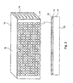
- FIG. 2 shows in the upper and the lower half in each case an embodiment of a structural unit 13, the LED's 11, which are arranged in a matrix and tightly packed on a circuit board 12 in the form of a matrix, wherein the circuit board 12 via metallic connecting elements 13 for discharging the through LED's 11 generated heat is connected to a heat sink 14.
- the heat sink 14 is substantially larger than that formed in the lower illustration, wherein the size of the heat sink can be configured in an application-specific manner.
- the heat sink 14 is provided with ventilation cuts 15, which serve to increase the surface area and thus the improved heat dissipation through the heat sink 14.
- FIG. 3 an exemplary embodiment of a block diagram 16 for the device 1 can be seen.
- the heart of the device 1 is thus formed by the control unit 17, which is connected to control the brightness of the LED's 11 with these.
- the control unit 17 is connected to the ventilation unit 18, which is designed for example as a fan, which is turned on by the control unit 17 when a predetermined temperature is exceeded.
- the control unit 17 is connected to a power supply 19 and to a battery 20, the battery being used, for example, only in the event of a power failure, and otherwise being recharged during operation.
- the device 1 according to the invention represents a film viewing device which, with relatively low energy consumption, enables a high-quality material examination in the form of a film view by giving maximum radiation homogeneity at maximum radiation efficiency.
Landscapes
- Physics & Mathematics (AREA)
- General Physics & Mathematics (AREA)
- Optics & Photonics (AREA)
- Apparatus For Radiation Diagnosis (AREA)
Applications Claiming Priority (1)
| Application Number | Priority Date | Filing Date | Title |
|---|---|---|---|
| DE200720013314 DE202007013314U1 (de) | 2007-09-21 | 2007-09-21 | Vorrichtung zum Betrachten eines Films |
Publications (2)
| Publication Number | Publication Date |
|---|---|
| EP2040108A2 true EP2040108A2 (fr) | 2009-03-25 |
| EP2040108A3 EP2040108A3 (fr) | 2009-09-23 |
Family
ID=38922553
Family Applications (1)
| Application Number | Title | Priority Date | Filing Date |
|---|---|---|---|
| EP08010044A Withdrawn EP2040108A3 (fr) | 2007-09-21 | 2008-06-02 | Dispositif de visionnement d'un film |
Country Status (2)
| Country | Link |
|---|---|
| EP (1) | EP2040108A3 (fr) |
| DE (1) | DE202007013314U1 (fr) |
Families Citing this family (1)
| Publication number | Priority date | Publication date | Assignee | Title |
|---|---|---|---|---|
| CN104257472A (zh) * | 2014-10-24 | 2015-01-07 | 董卫芹 | 一种多功能病床 |
Family Cites Families (2)
| Publication number | Priority date | Publication date | Assignee | Title |
|---|---|---|---|---|
| DE20304543U1 (de) * | 2003-03-21 | 2003-09-25 | Fürnrohr, Thomas, 92358 Seubersdorf | Leuchtdioden Röntgenfilmbetrachter |
| US20060028822A1 (en) * | 2004-08-09 | 2006-02-09 | Tanamachi Steven W | Medical image viewing apparatus and method |
-
2007
- 2007-09-21 DE DE200720013314 patent/DE202007013314U1/de not_active Expired - Lifetime
-
2008
- 2008-06-02 EP EP08010044A patent/EP2040108A3/fr not_active Withdrawn
Also Published As
| Publication number | Publication date |
|---|---|
| EP2040108A3 (fr) | 2009-09-23 |
| DE202007013314U1 (de) | 2008-01-10 |
Similar Documents
| Publication | Publication Date | Title |
|---|---|---|
| DE102016006891A1 (de) | Laservorrichtung, bei der ein Laseroszillationsteil, eine Luftkühlmaschine und ein Entfeuchter durch allgemeines Kühlwasser gekühlt werden | |
| DE102014104851B4 (de) | Vorrichtung zur Entkeimung mittels ultravioletter Strahlung | |
| DE202015102962U1 (de) | LED-Lampe | |
| WO2016041994A1 (fr) | Dispositif d'éclairage et procédé permettant de faire fonctionner un éclairage | |
| DE102013006995A1 (de) | Ringbeleuchtungsvorrichtung für ein Mikroskopobjektiv und Mikroskopobjektiv | |
| DE102007033455B4 (de) | Beleuchtungsvorrichtung für die Blitzlichtfotografie | |
| EP2040108A2 (fr) | Dispositif de visionnement d'un film | |
| DE102018118504B4 (de) | Leuchte | |
| AT506565B1 (de) | Mikroskopständer | |
| EP3081855B1 (fr) | Projecteur | |
| DE10246889B4 (de) | Beleuchtungseinrichtung für ein optisches Vergrösserungsgerät sowie optisches Vergrösserungsgerät | |
| DE102011086498B4 (de) | Projektionsanlage | |
| DE202012003623U1 (de) | Leuchte zur Beleuchtung von Räumen o. ä. | |
| DE202009014794U1 (de) | Beleuchtungseinrichtung und Lampe für diese | |
| DE202008015804U1 (de) | Eine elektrodenlose lichtemittierende Röhrendiode | |
| EP1662248A2 (fr) | Support de source de rayonnement pour un appareil de résistance aux intempéries | |
| DE102007029316B4 (de) | Vorrichtung zum UV-Strahlungshärten | |
| DE102011076700A1 (de) | Anordnung zur Lichtabgabe | |
| DE20100642U1 (de) | Beleuchtungsvorrichtung | |
| DE202010008278U1 (de) | LED-Leuchte | |
| WO2007095993A1 (fr) | Luminaire, notamment à but MEDICOlégal, comprenant plusieurs sources de lumière | |
| DE102011082225A1 (de) | Projektor | |
| WO2013045092A1 (fr) | Microscope opératoire avec un composant générateur de chaleur et un dispositif de refroidissement | |
| DE112021005017T5 (de) | Apparat zum homogenisieren einer spektralausgabe | |
| WO2025003100A1 (fr) | Dispositif de test, système et procédé de test |
Legal Events
| Date | Code | Title | Description |
|---|---|---|---|
| PUAI | Public reference made under article 153(3) epc to a published international application that has entered the european phase |
Free format text: ORIGINAL CODE: 0009012 |
|
| AK | Designated contracting states |
Kind code of ref document: A2 Designated state(s): AT BE BG CH CY CZ DE DK EE ES FI FR GB GR HR HU IE IS IT LI LT LU LV MC MT NL NO PL PT RO SE SI SK TR |
|
| AX | Request for extension of the european patent |
Extension state: AL BA MK RS |
|
| PUAL | Search report despatched |
Free format text: ORIGINAL CODE: 0009013 |
|
| AK | Designated contracting states |
Kind code of ref document: A3 Designated state(s): AT BE BG CH CY CZ DE DK EE ES FI FR GB GR HR HU IE IS IT LI LT LU LV MC MT NL NO PL PT RO SE SI SK TR |
|
| AX | Request for extension of the european patent |
Extension state: AL BA MK RS |
|
| AKX | Designation fees paid | ||
| STAA | Information on the status of an ep patent application or granted ep patent |
Free format text: STATUS: THE APPLICATION IS DEEMED TO BE WITHDRAWN |
|
| 18D | Application deemed to be withdrawn |
Effective date: 20100324 |
|
| REG | Reference to a national code |
Ref country code: DE Ref legal event code: 8566 |