EP2040130A1 - Prozesskassette und bilderzeugungsvorrichtung - Google Patents
Prozesskassette und bilderzeugungsvorrichtung Download PDFInfo
- Publication number
- EP2040130A1 EP2040130A1 EP06780679A EP06780679A EP2040130A1 EP 2040130 A1 EP2040130 A1 EP 2040130A1 EP 06780679 A EP06780679 A EP 06780679A EP 06780679 A EP06780679 A EP 06780679A EP 2040130 A1 EP2040130 A1 EP 2040130A1
- Authority
- EP
- European Patent Office
- Prior art keywords
- electrophotographic photosensitive
- photosensitive member
- sealing
- sealing member
- photosensitive drum
- Prior art date
- Legal status (The legal status is an assumption and is not a legal conclusion. Google has not performed a legal analysis and makes no representation as to the accuracy of the status listed.)
- Granted
Links
Images




Classifications
-
- G—PHYSICS
- G03—PHOTOGRAPHY; CINEMATOGRAPHY; ANALOGOUS TECHNIQUES USING WAVES OTHER THAN OPTICAL WAVES; ELECTROGRAPHY; HOLOGRAPHY
- G03G—ELECTROGRAPHY; ELECTROPHOTOGRAPHY; MAGNETOGRAPHY
- G03G21/00—Arrangements not provided for by groups G03G13/00 - G03G19/00, e.g. cleaning, elimination of residual charge
- G03G21/16—Mechanical means for facilitating the maintenance of the apparatus, e.g. modular arrangements
- G03G21/18—Mechanical means for facilitating the maintenance of the apparatus, e.g. modular arrangements using a processing cartridge, whereby the process cartridge comprises at least two image processing means in a single unit
- G03G21/1803—Arrangements or disposition of the complete process cartridge or parts thereof
- G03G21/1828—Prevention of damage or soiling, e.g. mechanical abrasion
- G03G21/1832—Shielding members, shutter, e.g. light, heat shielding, prevention of toner scattering
Definitions
- the present invention relates to a process cartridge and an image forming apparatus which include a cleaning member for removing a development agent residual on an electrophotographic photosensitive member after a development agent image is transferred from the electrophotographic photosensitive member to a recording medium.
- An electrophotographic image forming apparatus forms a latent image on an electrophotographic photosensitive member, then develops the latent image with a development agent (hereinafter, referred to as "toner") into a visible image and transfers the toner image to a recording medium through a transfer means to complete image formation.
- a cleaning device removes extraneous matters such as transfer-residual toner from the electrophotographic photosensitive member, after the completion of transfer, in preparation for reuse of the electrophotographic photosensitive member.
- Fig. 9 illustrates a photosensitive drum 100 and a cleaning device 600, after transfer processing by a transfer means.
- the photosensitive drum 100 moves in the direction of an arrow A, so that transfer-residual toner 001 left on the photosensitive drum 100, which has not been transferred during the transfer processing, reaches the cleaning device 600.
- the cleaning device 600 includes a cleaning blade 601 having rubber elasticity, a housing portion 603 for housing extraneous matters such as transfer-residual toner removed by the cleaning blade 601, and a sealing sheet 602 as a sealing member.
- the sealing sheet 602 contacts with the surface of the photosensitive drum 100 upstream of the cleaning blade 601 in the direction of the movement of the photosensitive drum, in such a manner as to allow the toner on the photosensitive drum 100 to pass therethrough in the direction of the movement of the photosensitive drum 100.
- the cleaning blade 601 removes the transfer-residual toner 003 passed through a nip portion N between the sealing sheet 602 and the photosensitive drum 100, from the surface of the photosensitive drum 100.
- the sealing sheet 602 collects the removed toner 005 and causes it to be housed in the toner housing portion 603.
- the aforementioned sealing sheet 602 is placed obliquely with respect to the photosensitive drum 100, such that the free end thereof is in contact with the outer peripheral surface of the photosensitive drum 100. Further, the sealing sheet 602 is placed, such that the gap between the photosensitive drum 100 and the sealing sheet 602 is gradually decreased in the direction of the rotation of the photosensitive drum 100.
- a sealing sheet having elasticity is employed in order to prevent the occurrence of a gap at the nip portion N between the photosensitive drum 100 and the sealing sheet 26, and it is preferable to employ a sealing sheet which can intimately contact with the photosensitive drum 100. This is because a sealing sheet which can intimately contact therewith can prevent the toner scraped off by the cleaning blade 601 from being leaked to the outside of the housing portion through the nip portion N between the photosensitive drum 100 and the sealing sheet 602.
- sealing sheets made of thermoplastic urethane which have been known as preferable sealing sheets (Patent Literature 1). It is preferable that the contact pressure between the sealing sheet and the photosensitive drum has a value which does not damage the photosensitive layer in the photosensitive drum and allows the toner on the photosensitive drum to pass through the nip portion N along with the movement of the photosensitive drum.
- Patent Literature 1 Japanese Utility Model Application Publication No. 1-21323
- An image forming apparatus employing a cleaning device as illustrated in Fig. 9 may be configured to perform charge elimination on a photosensitive drum 100, at a position downstream of the position where the transfer processing is performed, but upstreamof the sealing sheet 602, in the direction of the movement of the photosensitive drum 100. This is because of the following reason. That is, by performing charge elimination on the photosensitive drum 100 before the transfer-residual toner thereon enters the cleaning device, it is possible to reduce the electrostatic adhesion of the transfer-residual toner to the photosensitive drum 100, which enables the cleaning device to preferably remove the transfer-residual toner.
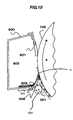
- the transfer-residual toner 002 intercepted by the sealing sheet 602 is deposited upstream of the nip portion at the contact between the photosensitive drum 100 and the sealing sheet 602, due to its mirror image forces and Van der Waals forces. Further, when the sealing sheet 602 and the photosensitive drum 100 are opened downwardly in the direction of the gravity, as illustrated in Fig. 10 , if a greater amount of toner is deposited, some toner 004 will drop therefrom due to the gravity. The toner may contaminate the inside of the image forming apparatus.
- the aforementioned object can be attained with the following configuration.
- An image forming apparatus including:
- the present invention it is possible to suppress the deposition of toner on the sealing member and suppress the dropping of deposited toner therefrom, at a high temperature and high humidity environment.
- a process cartridge 1100 is mounted to a mounting portion 1101 (see Fig. 2 ) provided in an image forming apparatus main body to constitute an electrophotographic image forming apparatus (hereinafter, referred to as "an image forming apparatus").
- the process cartridge 1100 includes a photosensitive drum 100, a charging roller 201, a development device 400, and a cleaning device 600, which are provided in a frame 1102, in order to enable handling them integrally.
- the process cartridge 1100 further includes, at a portion of the frame 1102, an opening 1001 which is a light passing portion for directing, to the photosensitive drum 100, charge elimination light generated from an LED light source 1000 (see Fig. 2 ).
- the image forming apparatus has a configuration as follows. At the center portion, there is placed the photosensitive drum 100 as an electrophotographic photosensitive member which enables forming an electrostatic latent image thereon. There are placed various types of processing means around the photosensitive drum 100. Namely, there are placed a charging device 200 which is a charging means for uniformly discharging/charging the photosensitive drum 100 with the negative polarity; an exposure device 300 for forming, through laser exposure, an electrostatic latent image corresponding to print information and image information, on the photosensitive drum 100 which has been charged; the development device 400 which is a development means for performing reversal development on the formed electrostatic latent image with toner being charged with the negative polarity for converting it into a visible image; a transfer device 500 which is a transfer means for transferring the visible toner images to a recording medium 900 which is a to-be-transferred member; the cleaning device 600 for removing transfer-residual toner and the like on the photosensitive drum 100; the LED light source 1000
- the image forming apparatus main body includes the LED light source 1000 as a charge elimination device
- the process cartridge 1100 includes the opening 1001 as a light passing portion for passing, therethrough, the charge elimination light generated from the LED light source 1000.
- the opening 1001 is provided in the frame 1102 of the process cartridge 1100 which includes the cleaning member, a housing portion and the like. Further, a transfer opening provided at the transfer position in the process cartridge 1100 may be utilized as the aforementioned opening 1001 or a scheme for guiding light through a light guide may be utilized.
- the process cartridge 1100 is configured to receive light directed from the outside in the present embodiment, the present invention is not limited thereto and the process cartridge 1100 may be configured to include an LED light source.
- the image forming apparatus main body or the process cartridge 1100 may be provided with a brush charge elimination device or the like as another charge elimination device for performing charge elimination.
- the charging device 200 includes the charging roller 201, supporting members (not illustrated), a spring member (not illustrated), and a charging bias power supply 202, as main components.
- the charging roller 201 according to the present embodiment is constituted by a conductive elastic layer made of urethane rubber or the like with a thickness of about 3 [mm] as a core and a higher resistance layer thereon which is made of urethane rubber with a thickness of several [mm] and carbon black dispersed therein.
- the supporting members are conductive and rotatably support the charging roller 201 at its opposite end portions.
- the spring member presses the charging roller 201 against the photosensitive drum 100 through these supporting members.
- the charging bias power supply 202 provided in the image forming apparatus main body applies a voltage to the charging roller 201 through the spring member and the supporting members.
- the charging roller 201 is installed, such that it is kept in contact with the photosensitive drum 100 and is driven to rotate in conjunction with the rotation of the photosensitive drum 100.
- a DC voltage of about -1000 V is applied to the charging roller 201 through the charging bias power supply 202 to charge the surface of the photosensitive drum 100 at a dark potential (VD) of -500 V.
- the photosensitive drum 100 After the photosensitive drum 100 is charged at its surface to the dark voltage by the charging device 200, the photosensitive drum 100 is subjected to light exposure corresponding to print information and image information and the like through the exposure device 300 to form an electrostatic latent image thereon.
- the potential at the portion subjected to the light exposure is changed to a light potential (VL) of -100 V.
- the development device 400 is partitioned, through a partition portion 405, into a hopper portion 406 for storing toner and a development chamber 407. Further, an agitating device 404 is placed in the hopper portion 406 to supply toner to the development chamber 407. In the development chamber 407, there are placed a development roller 401, a supply roller 402, and a development-agent restriction blade 403.
- the development roller 401 includes a two-layer configuration constituted by a base layer with a diameter of 16 [mm] made of silicon rubber and a coating made of acrylic urethane rubber applied to the surface thereof and performs development on the electrostatic latent image on the photosensitive drum 100. Further, the supply roller 402 includes a urethane sponge with a diameter of 16 [mm] for supplying toner to the development roller 401.
- the development-agent restriction blade 403 made of metal restricts the thickness of the toner layer on the development roller 401.
- the aforementioned agitating device 404, the development roller 401, and the supply roller 402 are configured to be driven from the outside and, during developing processing, they are kept rotated to supply toner to the photosensitive drum 100.
- the developing roller 401 is installed, such that it is kept in contact with the photosensitive drum 100 for performing development.
- a DC voltage of about -300 V is applied to the development roller 401 through a development bias power supply 408 so that the development roller 401 performs reversal development on the electrostatic latent image formed on the photosensitive drum 100 to convert the electrostatic latent image into a visible toner image.
- the transfer device 500 includes a transfer roller 501 made of an EPDM sponge with a diameter of 12 [mm], and a transfer bias power supply 502 for applying a voltage to the transfer roller 501.
- the voltage applied to the transfer roller 501 is controlled to a constant voltage during image formation.
- the toner image on the photosensitive drum 100 is transferred to the recording medium 900.
- the recording medium 900 housed within the cassette 700 which is a feeding device is supplied to a registration roller 702 through a feeding roller 701, in syncronization with the formation of the visible image on the photosensitive drum 100. Then, the recording medium 900 is transferred, through the registration roller 702, to the portion between the transfer roller 501 and the photosensitive drum 100, in syncronization with the tip end of the visible image formed on the photosensitive drum 100.
- a DC voltage of about +2000 V is applied to the transfer roller 501 so that the toner image is transferred to the recording medium 900.
- the toner image transferred to the recording medium 900 is transferred, along with the recording medium 900, to the fixing device 800.
- the fixing device 800 applies heat and a pressure to the toner image to fix it into a recorded image.
- the portion of the photosensitive drum 100 which has passed through the transfer device 500 is subj ected to charge elimination processing through the charge elimination light from the LED light source 1000 so that the potential at the surface thereof is changed to about 0 V.
- the transfer-residual toner on the photosensitive drum 100 is passed through a sealing sheet 602 as a sealing member which lightly contacts with the photosensitive drum 100. Thereafter, the transfer-residual toner is removed from the photosensitive drum 100 by a cleaning blade 601 which is a cleaning member made of polyurethane rubber. Then, the removed toner is housed in a waste toner housing portion 603. Thereafter, the surface of the photosensitive drum 100 is charged again by the charging device 200 in preparation for the next image formation.
- the image forming apparatus according to the present embodiment employed, as a developing agent, spherical toner with an average particle diameter of 6 [mm] and an average roundness of 0.970.
- the use of toner with an average roundness equal to or greater than 0.950 could significantly improve the fogging characteristic and the transferability and, therefore, was preferable.
- a conductive layer with a thickness of 15 ( ⁇ m) was formed on an aluminum cylinder and, then, an under coating layer with a thickness of 0.7 [mm] was formed on the conductive layer. Then, a coating for a charge generating layer was applied on the under coating layer, through immersion coating, to form a charge generating layer.
- This coating was applied to the aforementioned charge generating layer through immersion coating and, then, was dried at 120°C for 1 hour to forma charge transport layer with a thickness of 20 [mm].
- the collectability of transfer-residual toner at the nip portion N was evaluated, using sealing sheets 602 made of different types of materials.
- the evaluations were conducted such that the calculated value of the contact pressure between the photosensitive drum 100 and each sealing sheet per unit longitudinal length (the calculation method will be described later) fell in the range of 0.2156 ⁇ 10 -3 [N/mm] to 1.519 ⁇ 10 -3 [N/mm].
- the aforementioned calculated value is smaller than 0.2156 ⁇ 10 -3 [N/mm] (0.22 gf/mm), this will increase the difficulty of uniformly bringing the sealing sheet into contact with the photosensitive drum 100. If the aforementioned calculated value is greater than 1.519 ⁇ 10 -3 [N/mm] (0.155 gf/mm), this will cause the sealing sheet to physically scrape off transfer-residual toner. This may degrade the toner collectability regardless of the material of the sheet and therefore is unpreferable.
- the contact pressure was approximated to a calculated value.
- the sealing sheet 602 adhered and secured to an insulating bearing surface 604 is in contact with the photosensitive drum 100 at its tip end and is deflected thereby.
- the calculated value of the contact pressure P(N) between the sealing sheet 602 having a significantly small thickness as that used in an image forming apparatus and the photosensitive drum 100 per unit longitudinal length (1mm) can be calculated from the following equation (A) using a general formula defining the relationship between the force acting on a cantilever spring and the deflection thereof.
- the amount of deflection of the sealing sheet 602 is ⁇ [mm]
- the distance from the fixed end of the sealing sheet to the upstream side of the nip portion at the contact between the sealing sheet and the electrophotographic photosensitive member is 1 [mm]
- the thickness of the sealing sheet is h [mm].
- E is the Young's modulus of the sealing sheet (N/mm 2 )
- ⁇ is the Poisson's ratio of the sealing sheet.
- the sealing sheet 602 was in contact with the photosensitive drum 100 substantially at its tip end. Accordingly, the distance 1 from the fixed end of the sealing sheet 602 to the upstream side of the nip portion at the contact between the sealing sheet 602 and the photosensitive drum 100 was approximated to the distance from the fixed end of a sealing sheet 602' to the free end thereof. Further, it was difficult to directly determine the amount of deflection of the sealing sheet 602. Accordingly, the amount of deflection of the sealing sheet 602 was determined through a geometrical calculation, on the basis of the thickness of the sealing sheet 602, the position of the bearing surface 602, and the position at which the sealing sheet 602 and the photosensitive drum 100 was in contact with each other.
- the sealing sheets 602 formed from the aforementioned 6 types of sheet members and the aforementioned photosensitive drum A or the aforementioned photosensitive drum B were employed to form an image forming apparatus as described in Fig. 2 .
- the sealing sheet A was brought into contact with the photosensitive drum 100 at its surface having Al vapor-deposited thereon. Further, the sealing sheet F was brought into contact with the photosensitive drum 100 at its surface having the Teflon sheet (registered trademark) adhered thereon.
- the sealing sheet A was usually conductive, but it was adhered to the insulation bearing surface 604 and is not electrically connected to the other members.
- image formation was performed on 2000 paper sheets with a printing ratio of 8% (characters were output onto the entire surfaces of A4-size paper sheets with a printing ratio of 8%) and, then, the tendency of deposition of the transfer-residual toner was evaluated.
- Table. 1 illustrates the result along with the calculated values of the contact pressures of the sealing sheets.
- the collectability of transfer-residual toner was evaluated as the following four levels on the basis of the amount of toner deposited upstream of the nip portion at the contact between the sealing sheet 602 and the photosensitive drum 100.
- the work function ( ⁇ ) of a substance is the energy necessary for taking out electrons from the substance. If there is a larger work function difference between two members, frictional electrification caused between the two members will cause a greater electric field therebetween. If there is a smaller work function difference between two members, frictional electrification caused between the two members will cause a smaller electric field therebetween.
- the determination of the work function can be conducted according to the following determination method.
- the method can determine the work function as a numerical energy value [eV] required for taking out electrons from the substance and can also evaluate the charging polarities of the photosensitive drums and the sealing sheets.
- the determination of the work functions ( ⁇ ) can be conductedusing a surface analysis apparatus (AC-2, manufactured by Riken Keiki Co., Ltd.).
- a deuterium lamp was employed and the amount of irradiation light was properly set.
- monochromatic light was selected through a spectrometer and the selected monochromatic light was directed to a sample with a spot size of 4 [mm] ⁇ 4[mm], over an energy scanning range of 3.4 to 6.2 [eV], for a determination time period of 10 [sec/point].
- photoelectrons emitted from the sample surface were detected, and the work function was determined through calculation processing using work-function calculation software incorporated in the surface analysis apparatus.
- the determination of the work function was conducted with a repeat accuracy (standard deviation) of 0.02 [eV].
- the determinations of the work functions of the photosensitive drums 100 and the sealing sheets 602 were conducted, using the photosensitive drums and the sealing sheets which had been used for image formation on 2000 paper sheets with a printing ratio of 8% (outputting characters onto the entire surfaces of A4-size paper sheets with a printing ratio of 8%) at a high temperature and high humidity environment (at a temperature of 30°C and a humidity of 80%).
- a high temperature and high humidity environment at a temperature of 30°C and a humidity of 80%.
- the photosensitive drums and the sealing sheets for use as the determination samples were placed for 24 hours under the condition of a usage temperature of 25°C and a humidity of 55%, after the aforementioned image formation.
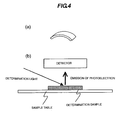
- the sample is irradiated with determination light with a spot of 4 [mm] ⁇ 4 [mm] as described above. Accordingly, such as sheet-shaped sample was cut into a test sample piece with a size of at least 1 [cm] ⁇ 1 [cm] and, then, the resultant test sample piece was secured to a sample table for determination.
- a cylindrical shaped test sample such as a photosensitive drum 100 was used as a sample
- the cylindrical shaped test sample was cut into a determination test sample piece with a shape illustrated in Fig. 4(a) .
- the determination test sample was secured to the sample table at a predetermined position thereon, such that the to-be-irradiated surface thereof was smooth in the direction of irradiation of the determination light.
- a detector photomultiplier
- Fig. 5 illustrates an exemplary chart resulted from the use of the surface analysis apparatus for the sealing sheet B.
- circle marks indicate measurement values and broken lines are approximate lines connecting these circle marks to oneanother.
- the horizontal axis represents the photon energy [eV]
- the vertical axis represents the emission yield [cps 0.5 ] (0.5 th power of the photoelectron yield per unit photoelectron), which offers a certain inclination [emission yield/photon energy].
- the work function is defined as the excitation energy value [eV] at the point where the broken line is bent (designated as (B) in Fig. 5 ).
- the excitation energy value is 5.33 [eV].
- Table. 2 illustrates the results of the determinations of the work functions of the photosensitive drum A and the sealing sheets A to F determined according to the aforementioned determination method, along with the result of the experiment 1 illustrated in Table. 1.
- Table. 2 shows the tendency to improve the collectability of transfer-residual toner with increasing difference between the work function of the photosensitive drum A which is 5.45 [eV] and the work function of the sealing sheet A to F.
- Table. 3 illustrates the results of the determinations of the work functions of the photosensitive drum B and the sealing sheets A, B, and D to F determined according to the aforementioned determination method, along with the result of the experiment 1 illustrated in Table. 1.
- Table. 3 shows the tendency to improve the collectability of transfer-residual toner with increasing difference between the work function of the photosensitive drum B which is 5.56 [eV] and the work functions of the sealing sheets A, B, and D to F.
- Fig. 6 illustrates the relationship between the absolute value of the work function difference between the photosensitive drum 100 and the sealing sheet 602 and the collectability of transfer-residual toner, which was resulted from the experiment 2.
- the horizontal axis represents the work function difference [eV] between the photosensitive drum 100 and the sealing sheet 602
- the vertical axis represents the collectability of transfer-residual toner (the numerical values thereon indicate the aforementioned levels of the toner deposition tendency).
- smaller values on the vertical axis indicate more preferable collectability.
- Fig. 6 shows that there is a correlation between the collectability of transfer-residual toner and the work function difference between the photosensitive drum 100 and the sealing sheet 602. Namely, it shows that the collectability of transfer-residual toner is degraded as the work function difference between the photosensitive drum 100 and the sealing sheet 602 reaches 0 [eV], and the collectability becomes more preferable as the difference is increased.
- Fig. 7 is a graph of the plot of the result of the experiment 2, wherein the horizontal axis represents "the calculated value of the contact pressure between the photosensitive drum 100 and the sealing sheet 602", while the vertical axis represents “the work function difference between the photosensitive drum 100 and the sealing sheet 602".
- the shapes of plots "a circular shape”, “a circular-triangular shape”, “a triangular shape”, and “a cross shape” indicate the aforementioned four levels of the toner deposition tendency, wherein "the circular shape”, “the circular-triangular shape”, “the triangular shape” and “the cross shape” indicate the aforementioned levels 1, 2, 3, and 4, respectively.
- a cleaning device including a cleaning member which contacts with an electrophotographic photosensitive member for cleaning the surface of this electrophotographic photosensitive member, a housing portion for collecting extraneous matters removed by the cleaning member and a sealing member which contacts with the surface of the electrophotographic photosensitive member upstream of the cleaning member in the direction of the movement of the electrophotographic photosensitive member for sealing the aforementioned housing portion, if the sealing member is selected, such that the work function difference between the electrophotographic photosensitive member and the sealing member is equal to or greater than 0.25 [eV], it is possible to prevent transfer-residual toner from being deposited even at a high temperature and high-humidity environment, thereby suppressing the malfunctions of the collection of transfer-residual toner.
- the aforementioned effect is due to the following fact. That is, when there is a larger work function difference between the electrophotographic photosensitive member and the sealing member, the frictional electrification caused therebetween induces a greater electric field therebetween. Namely, when transfer-residual toner is collected in the waste toner housing portion through the sealing member, the transfer-residual toner is collected while being electrically held on any one of the electrophotographic photosensitive member and the sealing member, due to the electric field generated between the electrophotographic photosensitive member and the sealing member. Accordingly, when there is a greater work function difference between the electrophotographic photosensitive member and the sealing member, the malfunctions of the collection of transfer-residual toner can be suppressed. Therefore, it is preferable to employ a configuration capable of maintaining electric charges in the sealing member caused by the frictional electrification in order to offer the effects of the present invention.
- such a configuration capable of maintaining electric charges caused in the sealing member was realized by using a sealing member made of an insulation material (the sealing sheets B to F) or by using a conductive sealing member (the sealing sheet A) and an insulation bearing surface for adhering the sealing member thereon.
- the result of the present experiment reveals that, when the work function difference between the electrophotographic photosensitive member and the sealing member is equal to or greater than 0.25 [eV], the malfunctions of the collection can be suppressed regardless of whether the value of ⁇ - ⁇ is positive or negative. Therefore, it is considered that the charging polarity and the work function of the developing agent have less influence on the collectability of transfer-residual toner.
- the transfer-residual toner deposited upstream of the nip portion at the contact between the sealing sheet 602 and the photosensitive drum 100 will drop downwardly due to the gravity with time. Therefore, the present invention is effective, particularly when the photosensitive drum 100 and the sealing sheet 602 are opened downwardly in the direction of the gravity.
- the present invention is effective in the case where the nip portion N between the sealing sheet and the electrophotographic photosensitive member falls in an ⁇ region which is painted in Fig. 8 , when the process cartridge is mounted in the image forming apparatus main body.
- the nip portion falls in the range of a rotation angle ⁇ of from 135° to 225°, wherein the rotation angle ⁇ is the angle in the direction opposite to the direction A of the rotation of the photosensitive drum, when it is assumed that, in a two-dimensional coordinate system having an origin point at the center of the rotation of the photosensitive drum 100, the horizontal axis is at 0°.
- the aforementioned rotation angle ⁇ was 200°.
- the present invention is not limited thereto.
- the present invention is also effective when the cleaning device is undetachably provided in the image forming apparatus main body.
- the present invention is also effective when the process cartridge includes at least a cleaning device.
- the opening 1001 for passing, therethrough, charge elimination light emitted from the LED light source 1000 as a charge elimination device for eliminating charge from the surface of the photosensitive drum or there is provided a charge elimination device other than an LED light source in the present embodiment.
- the aforementioned charge elimination device can be configured to perform charge elimination using the exposure device for applying exposure to the surface of the photosensitive drum 100.
- the present invention is applicable to image forming apparatus such as copiers, printers and the like and to process cartridges for use therein.
Landscapes
- Engineering & Computer Science (AREA)
- Computer Vision & Pattern Recognition (AREA)
- Physics & Mathematics (AREA)
- General Physics & Mathematics (AREA)
- Cleaning In Electrography (AREA)
- Discharging, Photosensitive Material Shape In Electrophotography (AREA)
- Photoreceptors In Electrophotography (AREA)
- Electrophotography Configuration And Component (AREA)
Applications Claiming Priority (1)
| Application Number | Priority Date | Filing Date | Title |
|---|---|---|---|
| PCT/JP2006/313112 WO2008001463A1 (en) | 2006-06-30 | 2006-06-30 | Process cartridge and image forming apparatus |
Publications (3)
| Publication Number | Publication Date |
|---|---|
| EP2040130A1 true EP2040130A1 (de) | 2009-03-25 |
| EP2040130A4 EP2040130A4 (de) | 2012-11-28 |
| EP2040130B1 EP2040130B1 (de) | 2017-08-09 |
Family
ID=38845238
Family Applications (1)
| Application Number | Title | Priority Date | Filing Date |
|---|---|---|---|
| EP06780679.4A Not-in-force EP2040130B1 (de) | 2006-06-30 | 2006-06-30 | Prozesskassette und bilderzeugungsvorrichtung |
Country Status (4)
| Country | Link |
|---|---|
| EP (1) | EP2040130B1 (de) |
| JP (1) | JP4764481B2 (de) |
| CN (1) | CN101292201B (de) |
| WO (1) | WO2008001463A1 (de) |
Cited By (1)
| Publication number | Priority date | Publication date | Assignee | Title |
|---|---|---|---|---|
| US11022933B2 (en) | 2019-05-17 | 2021-06-01 | Canon Kabushi Kikaisha | Process cartridge, image forming apparatus and cleaning apparatus |
Families Citing this family (8)
| Publication number | Priority date | Publication date | Assignee | Title |
|---|---|---|---|---|
| JP2013200528A (ja) * | 2012-03-26 | 2013-10-03 | Fuji Xerox Co Ltd | 電子写真感光体、プロセスカートリッジ、及び画像形成装置 |
| JP5963687B2 (ja) * | 2013-01-18 | 2016-08-03 | 京セラドキュメントソリューションズ株式会社 | ドラムユニット及びこれを備えた画像形成装置 |
| JP2018180394A (ja) * | 2017-04-18 | 2018-11-15 | 京セラドキュメントソリューションズ株式会社 | 画像形成装置 |
| JP7229757B2 (ja) * | 2018-12-21 | 2023-02-28 | キヤノン株式会社 | クリーニング装置、プロセスカートリッジおよび画像形成装置 |
| US10871743B2 (en) | 2018-12-21 | 2020-12-22 | Canon Kabushiki Kaisha | Cleaning device for removing a developer, process cartridge and image forming apparatus |
| JP7183029B2 (ja) * | 2018-12-21 | 2022-12-05 | キヤノン株式会社 | クリーニング装置、カートリッジ及び画像形成装置 |
| JP7183030B2 (ja) * | 2018-12-21 | 2022-12-05 | キヤノン株式会社 | クリーニング装置、プロセスカートリッジ及び画像形成装置 |
| IT202200021093A1 (it) | 2022-10-13 | 2024-04-13 | Univ Degli Studi Di Torino | Metodo per ottenere nanoparticelle lipidiche solide a partire da saponi naturali |
Family Cites Families (16)
| Publication number | Priority date | Publication date | Assignee | Title |
|---|---|---|---|---|
| JPS63113486A (ja) * | 1986-10-30 | 1988-05-18 | Seiko Epson Corp | 回収トナ−量検出装置 |
| JPS6421323U (de) | 1987-08-26 | 1989-02-02 | ||
| JPH03233479A (ja) * | 1989-12-07 | 1991-10-17 | Fujitsu Ltd | 現像装置 |
| JPH03194582A (ja) * | 1989-12-22 | 1991-08-26 | Sharp Corp | 画像形成装置 |
| JPH0627861A (ja) * | 1991-09-12 | 1994-02-04 | Canon Inc | クリーニング装置及び前記クリーニング装置を有する画像形成装置及びクリーニング装置の組立て方法 |
| JPH10333523A (ja) * | 1997-05-29 | 1998-12-18 | Konica Corp | 画像形成装置 |
| JP2000227668A (ja) | 1999-02-04 | 2000-08-15 | Canon Inc | 電子写真感光体、プロセスカートリッジ及び電子写真装置 |
| JP2000267426A (ja) * | 1999-03-16 | 2000-09-29 | Canon Inc | 現像装置及び画像形成装置 |
| JP2000330439A (ja) * | 1999-03-16 | 2000-11-30 | Canon Inc | すくいシート、クリーニング装置、プロセスカートリッジ及び画像形成装置 |
| JP3724555B2 (ja) * | 2000-04-21 | 2005-12-07 | セイコーエプソン株式会社 | 正帯電用電子写真感光体、その製造方法および画像形成装置 |
| JP4235790B2 (ja) * | 2001-06-22 | 2009-03-11 | セイコーエプソン株式会社 | 画像形成装置 |
| JP2004133262A (ja) * | 2002-10-11 | 2004-04-30 | Canon Inc | 現像装置、クリーニング装置、画像形成装置、及びプロセスカートリッジ |
| WO2005033805A1 (ja) * | 2003-10-02 | 2005-04-14 | Sharp Kabushiki Kaisha | クリーニング装置 |
| JP4060809B2 (ja) * | 2004-02-23 | 2008-03-12 | シャープ株式会社 | 画像形成装置 |
| JP4432554B2 (ja) * | 2004-03-16 | 2010-03-17 | 富士ゼロックス株式会社 | 画像形成装置 |
| JP2005274817A (ja) * | 2004-03-24 | 2005-10-06 | Seiko Epson Corp | トナー及びそのトナーを用いた画像形成装置 |
-
2006
- 2006-06-30 JP JP2008522266A patent/JP4764481B2/ja not_active Expired - Fee Related
- 2006-06-30 CN CN2006800394079A patent/CN101292201B/zh not_active Expired - Fee Related
- 2006-06-30 WO PCT/JP2006/313112 patent/WO2008001463A1/ja not_active Ceased
- 2006-06-30 EP EP06780679.4A patent/EP2040130B1/de not_active Not-in-force
Cited By (1)
| Publication number | Priority date | Publication date | Assignee | Title |
|---|---|---|---|---|
| US11022933B2 (en) | 2019-05-17 | 2021-06-01 | Canon Kabushi Kikaisha | Process cartridge, image forming apparatus and cleaning apparatus |
Also Published As
| Publication number | Publication date |
|---|---|
| EP2040130A4 (de) | 2012-11-28 |
| JP4764481B2 (ja) | 2011-09-07 |
| CN101292201B (zh) | 2010-06-09 |
| JPWO2008001463A1 (ja) | 2009-11-26 |
| WO2008001463A1 (en) | 2008-01-03 |
| EP2040130B1 (de) | 2017-08-09 |
| CN101292201A (zh) | 2008-10-22 |
Similar Documents
| Publication | Publication Date | Title |
|---|---|---|
| US7817954B2 (en) | Cleaning unit, image carrier unit including same, and image forming apparatus including same | |
| US7873298B2 (en) | Cleaning device, process cartridge, and image forming apparatus | |
| US8107872B2 (en) | Image forming apparatus and process cartridge | |
| EP2040130B1 (de) | Prozesskassette und bilderzeugungsvorrichtung | |
| JP2003316121A (ja) | プロセスカートリッジ及び画像形成装置 | |
| US7343109B2 (en) | Electrophotographic printer having developer and transfer bias control | |
| US20090052935A1 (en) | Charging apparatus, image forming unit that employs the charging apparatus, and image forming apparatus that employs the image forming unit | |
| JP4704081B2 (ja) | クリーニング装置、プロセスユニット、及び画像形成装置 | |
| US7409180B2 (en) | Image forming apparatus having toner remover to remove toner leaked from toner cartridge | |
| US7593670B2 (en) | Charging device including a contact charging member with silica thereon, process cartridge including a contact charging member, and image forming apparatus including such charging member | |
| US7599644B2 (en) | Process cartridge and image forming apparatus that eliminates charge from the surface of a photosensitive member upstream of a sealing member contact portion | |
| US12461465B2 (en) | Image-forming apparatus having charging potential control during non-image forming operation | |
| JP5044313B2 (ja) | クリーニング装置、これを用いた画像形成装置 | |
| JP4331158B2 (ja) | ブレードクリーニング用治具 | |
| JP2877373B2 (ja) | 帯電装置 | |
| KR102702450B1 (ko) | 크리닝 장치, 프로세스 카트리지 및 화상형성장치 | |
| JP3380087B2 (ja) | 画像形成装置 | |
| JP7183029B2 (ja) | クリーニング装置、カートリッジ及び画像形成装置 | |
| WO2025074973A1 (ja) | 画像形成装置及びカートリッジ | |
| JP2004138816A (ja) | クリーニング装置及び画像形成装置 | |
| JP2007058056A (ja) | 現像装置、プロセスカートリッジ、現像器カートリッジ、及び画像形成装置 | |
| JP2008275784A (ja) | ブレード清掃治具 | |
| JP2003316120A (ja) | プロセスカートリッジ及び画像形成装置 | |
| JPH056105A (ja) | 転写装置および画像形成装置 | |
| KR20200078342A (ko) | 클리닝 장치, 프로세스 카트리지 및 화상 형성장치 |
Legal Events
| Date | Code | Title | Description |
|---|---|---|---|
| PUAI | Public reference made under article 153(3) epc to a published international application that has entered the european phase |
Free format text: ORIGINAL CODE: 0009012 |
|
| 17P | Request for examination filed |
Effective date: 20090130 |
|
| AK | Designated contracting states |
Kind code of ref document: A1 Designated state(s): AT BE BG CH CY CZ DE DK EE ES FI FR GB GR HU IE IS IT LI LT LU LV MC NL PL PT RO SE SI SK TR |
|
| AX | Request for extension of the european patent |
Extension state: AL BA HR MK RS |
|
| DAX | Request for extension of the european patent (deleted) | ||
| A4 | Supplementary search report drawn up and despatched |
Effective date: 20121029 |
|
| RIC1 | Information provided on ipc code assigned before grant |
Ipc: G03G 21/10 20060101AFI20121023BHEP Ipc: G03G 5/047 20060101ALI20121023BHEP |
|
| 17Q | First examination report despatched |
Effective date: 20160613 |
|
| GRAP | Despatch of communication of intention to grant a patent |
Free format text: ORIGINAL CODE: EPIDOSNIGR1 |
|
| INTG | Intention to grant announced |
Effective date: 20170209 |
|
| GRAS | Grant fee paid |
Free format text: ORIGINAL CODE: EPIDOSNIGR3 |
|
| GRAA | (expected) grant |
Free format text: ORIGINAL CODE: 0009210 |
|
| AK | Designated contracting states |
Kind code of ref document: B1 Designated state(s): AT BE BG CH CY CZ DE DK EE ES FI FR GB GR HU IE IS IT LI LT LU LV MC NL PL PT RO SE SI SK TR |
|
| REG | Reference to a national code |
Ref country code: GB Ref legal event code: FG4D |
|
| REG | Reference to a national code |
Ref country code: CH Ref legal event code: EP Ref country code: AT Ref legal event code: REF Ref document number: 917491 Country of ref document: AT Kind code of ref document: T Effective date: 20170815 |
|
| REG | Reference to a national code |
Ref country code: IE Ref legal event code: FG4D |
|
| REG | Reference to a national code |
Ref country code: DE Ref legal event code: R096 Ref document number: 602006053293 Country of ref document: DE |
|
| REG | Reference to a national code |
Ref country code: NL Ref legal event code: MP Effective date: 20170809 |
|
| REG | Reference to a national code |
Ref country code: LT Ref legal event code: MG4D |
|
| REG | Reference to a national code |
Ref country code: AT Ref legal event code: MK05 Ref document number: 917491 Country of ref document: AT Kind code of ref document: T Effective date: 20170809 |
|
| PG25 | Lapsed in a contracting state [announced via postgrant information from national office to epo] |
Ref country code: FI Free format text: LAPSE BECAUSE OF FAILURE TO SUBMIT A TRANSLATION OF THE DESCRIPTION OR TO PAY THE FEE WITHIN THE PRESCRIBED TIME-LIMIT Effective date: 20170809 Ref country code: NL Free format text: LAPSE BECAUSE OF FAILURE TO SUBMIT A TRANSLATION OF THE DESCRIPTION OR TO PAY THE FEE WITHIN THE PRESCRIBED TIME-LIMIT Effective date: 20170809 Ref country code: LT Free format text: LAPSE BECAUSE OF FAILURE TO SUBMIT A TRANSLATION OF THE DESCRIPTION OR TO PAY THE FEE WITHIN THE PRESCRIBED TIME-LIMIT Effective date: 20170809 Ref country code: AT Free format text: LAPSE BECAUSE OF FAILURE TO SUBMIT A TRANSLATION OF THE DESCRIPTION OR TO PAY THE FEE WITHIN THE PRESCRIBED TIME-LIMIT Effective date: 20170809 Ref country code: SE Free format text: LAPSE BECAUSE OF FAILURE TO SUBMIT A TRANSLATION OF THE DESCRIPTION OR TO PAY THE FEE WITHIN THE PRESCRIBED TIME-LIMIT Effective date: 20170809 |
|
| PG25 | Lapsed in a contracting state [announced via postgrant information from national office to epo] |
Ref country code: LV Free format text: LAPSE BECAUSE OF FAILURE TO SUBMIT A TRANSLATION OF THE DESCRIPTION OR TO PAY THE FEE WITHIN THE PRESCRIBED TIME-LIMIT Effective date: 20170809 Ref country code: PL Free format text: LAPSE BECAUSE OF FAILURE TO SUBMIT A TRANSLATION OF THE DESCRIPTION OR TO PAY THE FEE WITHIN THE PRESCRIBED TIME-LIMIT Effective date: 20170809 Ref country code: BG Free format text: LAPSE BECAUSE OF FAILURE TO SUBMIT A TRANSLATION OF THE DESCRIPTION OR TO PAY THE FEE WITHIN THE PRESCRIBED TIME-LIMIT Effective date: 20171109 Ref country code: IS Free format text: LAPSE BECAUSE OF FAILURE TO SUBMIT A TRANSLATION OF THE DESCRIPTION OR TO PAY THE FEE WITHIN THE PRESCRIBED TIME-LIMIT Effective date: 20171209 Ref country code: ES Free format text: LAPSE BECAUSE OF FAILURE TO SUBMIT A TRANSLATION OF THE DESCRIPTION OR TO PAY THE FEE WITHIN THE PRESCRIBED TIME-LIMIT Effective date: 20170809 Ref country code: GR Free format text: LAPSE BECAUSE OF FAILURE TO SUBMIT A TRANSLATION OF THE DESCRIPTION OR TO PAY THE FEE WITHIN THE PRESCRIBED TIME-LIMIT Effective date: 20171110 |
|
| PG25 | Lapsed in a contracting state [announced via postgrant information from national office to epo] |
Ref country code: CZ Free format text: LAPSE BECAUSE OF FAILURE TO SUBMIT A TRANSLATION OF THE DESCRIPTION OR TO PAY THE FEE WITHIN THE PRESCRIBED TIME-LIMIT Effective date: 20170809 Ref country code: RO Free format text: LAPSE BECAUSE OF FAILURE TO SUBMIT A TRANSLATION OF THE DESCRIPTION OR TO PAY THE FEE WITHIN THE PRESCRIBED TIME-LIMIT Effective date: 20170809 Ref country code: DK Free format text: LAPSE BECAUSE OF FAILURE TO SUBMIT A TRANSLATION OF THE DESCRIPTION OR TO PAY THE FEE WITHIN THE PRESCRIBED TIME-LIMIT Effective date: 20170809 |
|
| REG | Reference to a national code |
Ref country code: DE Ref legal event code: R097 Ref document number: 602006053293 Country of ref document: DE |
|
| PG25 | Lapsed in a contracting state [announced via postgrant information from national office to epo] |
Ref country code: IT Free format text: LAPSE BECAUSE OF FAILURE TO SUBMIT A TRANSLATION OF THE DESCRIPTION OR TO PAY THE FEE WITHIN THE PRESCRIBED TIME-LIMIT Effective date: 20170809 Ref country code: EE Free format text: LAPSE BECAUSE OF FAILURE TO SUBMIT A TRANSLATION OF THE DESCRIPTION OR TO PAY THE FEE WITHIN THE PRESCRIBED TIME-LIMIT Effective date: 20170809 Ref country code: SK Free format text: LAPSE BECAUSE OF FAILURE TO SUBMIT A TRANSLATION OF THE DESCRIPTION OR TO PAY THE FEE WITHIN THE PRESCRIBED TIME-LIMIT Effective date: 20170809 |
|
| PLBE | No opposition filed within time limit |
Free format text: ORIGINAL CODE: 0009261 |
|
| STAA | Information on the status of an ep patent application or granted ep patent |
Free format text: STATUS: NO OPPOSITION FILED WITHIN TIME LIMIT |
|
| 26N | No opposition filed |
Effective date: 20180511 |
|
| PG25 | Lapsed in a contracting state [announced via postgrant information from national office to epo] |
Ref country code: SI Free format text: LAPSE BECAUSE OF FAILURE TO SUBMIT A TRANSLATION OF THE DESCRIPTION OR TO PAY THE FEE WITHIN THE PRESCRIBED TIME-LIMIT Effective date: 20170809 |
|
| REG | Reference to a national code |
Ref country code: CH Ref legal event code: PL |
|
| GBPC | Gb: european patent ceased through non-payment of renewal fee |
Effective date: 20180630 |
|
| REG | Reference to a national code |
Ref country code: BE Ref legal event code: MM Effective date: 20180630 |
|
| PG25 | Lapsed in a contracting state [announced via postgrant information from national office to epo] |
Ref country code: LU Free format text: LAPSE BECAUSE OF NON-PAYMENT OF DUE FEES Effective date: 20180630 Ref country code: MC Free format text: LAPSE BECAUSE OF FAILURE TO SUBMIT A TRANSLATION OF THE DESCRIPTION OR TO PAY THE FEE WITHIN THE PRESCRIBED TIME-LIMIT Effective date: 20170809 |
|
| REG | Reference to a national code |
Ref country code: IE Ref legal event code: MM4A |
|
| PG25 | Lapsed in a contracting state [announced via postgrant information from national office to epo] |
Ref country code: IE Free format text: LAPSE BECAUSE OF NON-PAYMENT OF DUE FEES Effective date: 20180630 Ref country code: GB Free format text: LAPSE BECAUSE OF NON-PAYMENT OF DUE FEES Effective date: 20180630 Ref country code: CH Free format text: LAPSE BECAUSE OF NON-PAYMENT OF DUE FEES Effective date: 20180630 Ref country code: LI Free format text: LAPSE BECAUSE OF NON-PAYMENT OF DUE FEES Effective date: 20180630 Ref country code: FR Free format text: LAPSE BECAUSE OF NON-PAYMENT OF DUE FEES Effective date: 20180630 |
|
| PG25 | Lapsed in a contracting state [announced via postgrant information from national office to epo] |
Ref country code: BE Free format text: LAPSE BECAUSE OF NON-PAYMENT OF DUE FEES Effective date: 20180630 |
|
| PG25 | Lapsed in a contracting state [announced via postgrant information from national office to epo] |
Ref country code: TR Free format text: LAPSE BECAUSE OF FAILURE TO SUBMIT A TRANSLATION OF THE DESCRIPTION OR TO PAY THE FEE WITHIN THE PRESCRIBED TIME-LIMIT Effective date: 20170809 |
|
| PG25 | Lapsed in a contracting state [announced via postgrant information from national office to epo] |
Ref country code: PT Free format text: LAPSE BECAUSE OF FAILURE TO SUBMIT A TRANSLATION OF THE DESCRIPTION OR TO PAY THE FEE WITHIN THE PRESCRIBED TIME-LIMIT Effective date: 20170809 Ref country code: HU Free format text: LAPSE BECAUSE OF FAILURE TO SUBMIT A TRANSLATION OF THE DESCRIPTION OR TO PAY THE FEE WITHIN THE PRESCRIBED TIME-LIMIT; INVALID AB INITIO Effective date: 20060630 |
|
| PG25 | Lapsed in a contracting state [announced via postgrant information from national office to epo] |
Ref country code: CY Free format text: LAPSE BECAUSE OF FAILURE TO SUBMIT A TRANSLATION OF THE DESCRIPTION OR TO PAY THE FEE WITHIN THE PRESCRIBED TIME-LIMIT Effective date: 20170809 |
|
| PGFP | Annual fee paid to national office [announced via postgrant information from national office to epo] |
Ref country code: DE Payment date: 20220518 Year of fee payment: 17 |
|
| REG | Reference to a national code |
Ref country code: DE Ref legal event code: R119 Ref document number: 602006053293 Country of ref document: DE |
|
| PG25 | Lapsed in a contracting state [announced via postgrant information from national office to epo] |
Ref country code: DE Free format text: LAPSE BECAUSE OF NON-PAYMENT OF DUE FEES Effective date: 20240103 |